Owner's Manual
Page 3
... Water Valve Tubes Assembly Method 16 8. Disassemble of fan Motor 17 9. Function on Icemaker...46 3. TROUBLE DIAGNOSIS...54 10. Refrigerator Shelves...8 4. Freezer Shelf...8 5. HOW TO DISASSEMBLY AND ASSEMBLY 11 1. Water Valve Disassembly Method 15 7. MICOM FUNCTION ...21 ... ...4 2. Fan Shroud Grille...14 5. Ice maker Assembly...14 6. Ice maker Troubleshooting 49 4. PARTS IDENTIFICATION ...5 3. Removing and Replacing Refrigerator door 11 2. Explanation for PCB circuit 30 7. Disassemble of Tray Drip 18 10. Monitor Panel...21 6. How to Control the amount...
... Water Valve Tubes Assembly Method 16 8. Disassemble of fan Motor 17 9. Function on Icemaker...46 3. TROUBLE DIAGNOSIS...54 10. Refrigerator Shelves...8 4. Freezer Shelf...8 5. HOW TO DISASSEMBLY AND ASSEMBLY 11 1. Water Valve Disassembly Method 15 7. MICOM FUNCTION ...21 ... ...4 2. Fan Shroud Grille...14 5. Ice maker Assembly...14 6. Ice maker Troubleshooting 49 4. PARTS IDENTIFICATION ...5 3. Removing and Replacing Refrigerator door 11 2. Explanation for PCB circuit 30 7. Disassemble of Tray Drip 18 10. Monitor Panel...21 6. How to Control the amount...

Owner's Manual
Page 4
... 2.To prevent electric shock,unplug before servicing. 3.Always check line voltage and amperage. 7.Before tilting the refrigerator, remove all materials from on or in the refrigerator. 8.When servicing the evaporator, wear gloves to prevent injuries from the sharp evaporator fins. 4.Use standard electrical... components. 5.Don't touch metal products in the freezer with wet hands.This may cause frost bite. 9.Service on the refrigerator should be performed by a qualified technician.Sealed system repair must be performed by a CFC certified technician. 6.Prevent water from spiling...
... 2.To prevent electric shock,unplug before servicing. 3.Always check line voltage and amperage. 7.Before tilting the refrigerator, remove all materials from on or in the refrigerator. 8.When servicing the evaporator, wear gloves to prevent injuries from the sharp evaporator fins. 4.Use standard electrical... components. 5.Don't touch metal products in the freezer with wet hands.This may cause frost bite. 9.Service on the refrigerator should be performed by a qualified technician.Sealed system repair must be performed by a CFC certified technician. 6.Prevent water from spiling...
Owner's Manual
Page 5
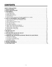
SPECIFICATIONS GENERAL FEATURES MODELS LSC27914SB /01 LSC27914SW /01 LSC27914TT /01 LSC27914ST /01 FREEZER REFRIGERATOR SPECIFICATIONS Color Dimensions Net Weight Capacity Refrigerant Climate class Rated Rating Cooling System Temperature Control Defrosting System Insulation Compressor Evaporator Condenser Lubricanting Oil Drier Capillary Tube First Defrost Defrost Cycle Desfrosting Device ...
SPECIFICATIONS GENERAL FEATURES MODELS LSC27914SB /01 LSC27914SW /01 LSC27914TT /01 LSC27914ST /01 FREEZER REFRIGERATOR SPECIFICATIONS Color Dimensions Net Weight Capacity Refrigerant Climate class Rated Rating Cooling System Temperature Control Defrosting System Insulation Compressor Evaporator Condenser Lubricanting Oil Drier Capillary Tube First Defrost Defrost Cycle Desfrosting Device ...
Owner's Manual
Page 6
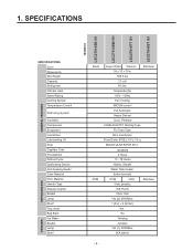
... E Drawer F Base Grille G Dairy Corner For storage of the items listed below may not match your model. PARTS IDENTIFICATION G A H B I Water Filter J Refrigerator Shelf K Snack Pan For storage of the features shown below . A Freezer Door Rack B Automatic Icemaker The ice is produced in the icemaker and sent to ...become more familiar with the parts and features. L Refrigerator Door Rack M Vegetable Drawer - 5 - The locations of meat or fresh food. Note: This guide covers several different models.The...
... E Drawer F Base Grille G Dairy Corner For storage of the items listed below may not match your model. PARTS IDENTIFICATION G A H B I Water Filter J Refrigerator Shelf K Snack Pan For storage of the features shown below . A Freezer Door Rack B Automatic Icemaker The ice is produced in the icemaker and sent to ...become more familiar with the parts and features. L Refrigerator Door Rack M Vegetable Drawer - 5 - The locations of meat or fresh food. Note: This guide covers several different models.The...
Owner's Manual
Page 7
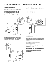
...leg Using a ¾" (19 mm) wrench, turn the keeper nut clockwise to level the refrigerator and freezer door. Adjust the level when the refrigerator door is higher than the refrigerator compartment door, make them level by inserting flat blade screwdriver into the groove of ½" ...can be pulled out. (Adjustable range of height is lower than the refrigerator compartment door, make them level by inserting flat blade screwdriver into the groove of the refrigerator. HOW TO INSTALL THE REFRIGERATOR 1. After setting the level door, turn the adjustment hinge pin clockwise...
...leg Using a ¾" (19 mm) wrench, turn the keeper nut clockwise to level the refrigerator and freezer door. Adjust the level when the refrigerator door is higher than the refrigerator compartment door, make them level by inserting flat blade screwdriver into the groove of ½" ...can be pulled out. (Adjustable range of height is lower than the refrigerator compartment door, make them level by inserting flat blade screwdriver into the groove of the refrigerator. HOW TO INSTALL THE REFRIGERATOR 1. After setting the level door, turn the adjustment hinge pin clockwise...
Owner's Manual
Page 8
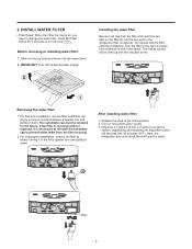
...filter is removed and not replaced, it is necessary to reinstall the substitute cap to change the water filter. After installing water filter 1. Open the refrigerator door and check the shelf area for the future. A Filter - 7 - Take out the top shelf and move it to the left a quarter... seconds ON, 60 seconds OFF). Turn the filter to the right a quarter turn clockwise to turn and pulling it into the two slots in the refrigerator filter receptacle. Installing the water filter Remove red cap from the filter housing. 2. Removing the water filter: 1. Dispense 2.5 gallons (9.46 L) of ...
...filter is removed and not replaced, it is necessary to reinstall the substitute cap to change the water filter. After installing water filter 1. Open the refrigerator door and check the shelf area for the future. A Filter - 7 - Take out the top shelf and move it to the left a quarter... seconds ON, 60 seconds OFF). Turn the filter to the right a quarter turn clockwise to turn and pulling it into the two slots in the refrigerator filter receptacle. Installing the water filter Remove red cap from the filter housing. 2. Removing the water filter: 1. Dispense 2.5 gallons (9.46 L) of ...

Owner's Manual
Page 9
Lift it to the direction , push the right part to the direction k , and take it at a height according to keep shelf horizontal while removing; REFRIGERATOR SHELVES The refrigeratoCr acormpaertmadenntMshaeilf ist andjuesntaablne csoethat you can place it out while lifting the rear part of foods. • Slide shelf Pull the shelf ...
Lift it to the direction , push the right part to the direction k , and take it at a height according to keep shelf horizontal while removing; REFRIGERATOR SHELVES The refrigeratoCr acormpaertmadenntMshaeilf ist andjuesntaablne csoethat you can place it out while lifting the rear part of foods. • Slide shelf Pull the shelf ...

Owner's Manual
Page 11
... in the ice. - 10 - Switch ON ON Switch OFF 1 2 3. Caution: • Unplug the power cord from the wall outlet and wait at 9s when the refrigerator is complete, check the level of 10.0 water pressure 4 ON ON 11.0 1) The water supplying time is set at least three minutes before removing the...
... in the ice. - 10 - Switch ON ON Switch OFF 1 2 3. Caution: • Unplug the power cord from the wall outlet and wait at 9s when the refrigerator is complete, check the level of 10.0 water pressure 4 ON ON 11.0 1) The water supplying time is set at least three minutes before removing the...
Owner's Manual
Page 12
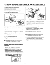
... through the lower hinge pin. 7. Remove the top hinge cover screw (1). 2. Lift the door from the lower hinge pin. 5. To remove the right (refrigerator) door: (1) (2) (3) (4) (5) Type 1 (4) (5) (3) Rivet Type 2 1. Remove the top hinge cover screw (1). 2. Open the door. Lift up.... Use a flat blade screwdriver to flow out. Lift up , on a nonscratching surface. 4. Figure 1 - 11 - REMOVING AND REPLACING REFRIGERATOR DOORS Before removing the doors, remove the base grille. CAUTION: When lifting the hinge free of the hinge lever latch (7). Lift the top ...
... through the lower hinge pin. 7. Remove the top hinge cover screw (1). 2. Lift the door from the lower hinge pin. 5. To remove the right (refrigerator) door: (1) (2) (3) (4) (5) Type 1 (4) (5) (3) Rivet Type 2 1. Remove the top hinge cover screw (1). 2. Open the door. Lift up.... Use a flat blade screwdriver to flow out. Lift up , on a nonscratching surface. 4. Figure 1 - 11 - REMOVING AND REPLACING REFRIGERATOR DOORS Before removing the doors, remove the base grille. CAUTION: When lifting the hinge free of the hinge lever latch (7). Lift the top ...
Owner's Manual
Page 13
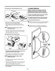
...Reconnect the water tubes by inserting the tubes into place. Keyhole slots on the back of the handle allow the handle to move the refrigerator through the lower hinge pin and place the door onto the lower hinge pin. 2. NOTE: Regardless of hinge lever type, removal ... tubes through a narrow opening in cabinet top. Position cover (2) into the connectors. - 12 - If necessary, follow the directions below to remove the refrigerator doors when it could be damaged or broken. HANDLE REMOVAL NOTE: It is the same. 3. Install the grounding screw (4) and connect all the wire ...
...Reconnect the water tubes by inserting the tubes into place. Keyhole slots on the back of the handle allow the handle to move the refrigerator through the lower hinge pin and place the door onto the lower hinge pin. 2. NOTE: Regardless of hinge lever type, removal ... tubes through a narrow opening in cabinet top. Position cover (2) into the connectors. - 12 - If necessary, follow the directions below to remove the refrigerator doors when it could be damaged or broken. HANDLE REMOVAL NOTE: It is the same. 3. Install the grounding screw (4) and connect all the wire ...
Owner's Manual
Page 22
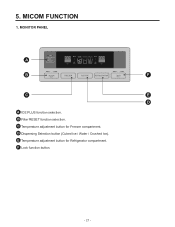
F Lock function button. - 21 - C Temperature adjustment button for Refrigerator compartment. B Filter RESET function selection. E Temperature adjustment button for Freezer compartment. MICOM FUNCTION 1. MONITOR PANEL A B F C E D A ICE PLUS function selection. D Dispensing Selection button (Cubed Ice / Water / Crushed Ice). 5.
F Lock function button. - 21 - C Temperature adjustment button for Refrigerator compartment. B Filter RESET function selection. E Temperature adjustment button for Freezer compartment. MICOM FUNCTION 1. MONITOR PANEL A B F C E D A ICE PLUS function selection. D Dispensing Selection button (Cubed Ice / Water / Crushed Ice). 5.
Owner's Manual
Page 23
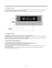
...seconds (Display return to dispensing icon (This depends on last selection dispensed). Press FREEZER and ICE PLUS buttons simultaneously to 37°F for refrigerator and 0°F for freezer. Once the mode activates, all loads are always OFF except to normal mode). - 22 - To deactivate ...is set to turn OFF with the recognition sound of "Ding~" (Be sure press both buttons for activation. 1-3. 1-1. You can adjust the Refrigerator and the Freezer control temperature by pressing the ADJUST button. 2) When the power initially applied or restored after , these will work ). Display ...
...seconds (Display return to dispensing icon (This depends on last selection dispensed). Press FREEZER and ICE PLUS buttons simultaneously to 37°F for refrigerator and 0°F for freezer. Once the mode activates, all loads are always OFF except to normal mode). - 22 - To deactivate ...is set to turn OFF with the recognition sound of "Ding~" (Be sure press both buttons for activation. 1-3. 1-1. You can adjust the Refrigerator and the Freezer control temperature by pressing the ADJUST button. 2) When the power initially applied or restored after , these will work ). Display ...
Owner's Manual
Page 24
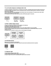
... and hold the LOCK button for 3 seconds. ICE PLUS selection Please select this function for operation. 1-7. Lock function (dispenser and display button lock) 1) When the refrigerator is pressed, dispenser light turns ON. 3) Dispenser light will turn ON after a preset time and must be selected each time for quick freezing. This function...
... and hold the LOCK button for 3 seconds. ICE PLUS selection Please select this function for operation. 1-7. Lock function (dispenser and display button lock) 1) When the refrigerator is pressed, dispenser light turns ON. 3) Dispenser light will turn ON after a preset time and must be selected each time for quick freezing. This function...
Owner's Manual
Page 25
...alarm, alarm is completed and it will automatically be controlled at high speed, it shall operate for BLDC motor failure. However, if the refrigerator door is opened while the fan motor is operating, the fan motor will continue to the standard speed). Door opening alarm 1) The ... 2) It controls at the single RPM without varying RPM. 3) Failure sensing method is pressed again, the freezer will turn off and on the refrigerator, for three hours. (4) If ICE PLUS is selected within seven minutes after compressor has stopped, the compressor (compressor delays seven minutes) shall start...
...alarm, alarm is completed and it will automatically be controlled at high speed, it shall operate for BLDC motor failure. However, if the refrigerator door is opened while the fan motor is operating, the fan motor will continue to the standard speed). Door opening alarm 1) The ... 2) It controls at the single RPM without varying RPM. 3) Failure sensing method is pressed again, the freezer will turn off and on the refrigerator, for three hours. (4) If ICE PLUS is selected within seven minutes after compressor has stopped, the compressor (compressor delays seven minutes) shall start...

Owner's Manual
Page 26
.... HEATER ON DAMPER OPEN - 25 - DEF HTR sec. COMP OFF 0.3 F-FAN sec. & C-FAN OFF 0.3 DEF sec. Refrigerator room lamp automatically off 1) The refrigerator compartment lamp will turn on for restoring power, defrosting starts when the compressor running tume reaches 4 hours. 3) Defrosting stops if the...defective (wires are opened. 2) For initial power on sequence won ´t function if its sensor is determinated by refrigerator door switch. 2) If the refrigerator compartment lamp will turn off by how often and how long the dorrs are cut or short circuited). 1-14. COMP...
.... HEATER ON DAMPER OPEN - 25 - DEF HTR sec. COMP OFF 0.3 F-FAN sec. & C-FAN OFF 0.3 DEF sec. Refrigerator room lamp automatically off 1) The refrigerator compartment lamp will turn on for restoring power, defrosting starts when the compressor running tume reaches 4 hours. 3) Defrosting stops if the...defective (wires are opened. 2) For initial power on sequence won ´t function if its sensor is determinated by refrigerator door switch. 2) If the refrigerator compartment lamp will turn off by how often and how long the dorrs are cut or short circuited). 1-14. COMP...
Owner's Manual
Page 27
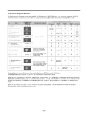
... Code Index) indicating the failure mode. - 26 - ITEM 1 No Error 2 Abnormal Freezer Sensor FAILURE CODE INDICATOR (F-Section) ALL LED ON CONTENTS OF FAILURE - 3 Abnormal Refrigerator Sensor (1) 4 Abnormal Refrigerator Sensor (2) 5 Abnormal Defrost Sensor 6 Abnormal Room Temperature Sensor 7 Abnormal Icemaker Sensor 8 Abnormal Defrost 9 Icemaker UNIT SEE NOTE (1) Cut o short circuit wire SEE NOTE (1) SEE...
... Code Index) indicating the failure mode. - 26 - ITEM 1 No Error 2 Abnormal Freezer Sensor FAILURE CODE INDICATOR (F-Section) ALL LED ON CONTENTS OF FAILURE - 3 Abnormal Refrigerator Sensor (1) 4 Abnormal Refrigerator Sensor (2) 5 Abnormal Defrost Sensor 6 Abnormal Room Temperature Sensor 7 Abnormal Icemaker Sensor 8 Abnormal Defrost 9 Icemaker UNIT SEE NOTE (1) Cut o short circuit wire SEE NOTE (1) SEE...
Owner's Manual
Page 28
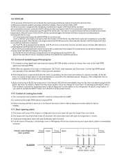
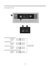
Failure Diagnosis Function D A B C ROOM TEMPERATURE SENSOR ABNORMAL: SECTION A TURNS OFF NORMAL: SECTION A TURNS ON ICEMAKER SENSOR ABNORMAL: NORMAL: SECTION B TURNS OFF SECTION B TURNS ON ICEMAKER UNIT FAILURE ABNORMAL: NORMAL: SECTION C TURNS OFF SECTION C TURNS ON REFRIGERATOR SENSOR (2) [MIDDLE ROOM] ABNORMAL: SECTION D TURNS OFF NORMAL: SECTION D TURNS ON The other display graphics Turn On - 27 -
Failure Diagnosis Function D A B C ROOM TEMPERATURE SENSOR ABNORMAL: SECTION A TURNS OFF NORMAL: SECTION A TURNS ON ICEMAKER SENSOR ABNORMAL: NORMAL: SECTION B TURNS OFF SECTION B TURNS ON ICEMAKER UNIT FAILURE ABNORMAL: NORMAL: SECTION C TURNS OFF SECTION C TURNS ON REFRIGERATOR SENSOR (2) [MIDDLE ROOM] ABNORMAL: SECTION D TURNS OFF NORMAL: SECTION D TURNS ON The other display graphics Turn On - 27 -
Owner's Manual
Page 29
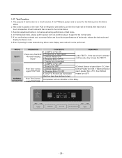
... failure part at the failure status. 2. 1-17. If Defrost Sensor is to the normal status. 3. Function adjustment button is placed on the main PCB of refrigerator (test switch), and the test mode will turn ON after maximum 2 hours irrespective of test mode, release the test mode and display the failure code...
... failure part at the failure status. 2. 1-17. If Defrost Sensor is to the normal status. 3. Function adjustment button is placed on the main PCB of refrigerator (test switch), and the test mode will turn ON after maximum 2 hours irrespective of test mode, release the test mode and display the failure code...
Owner's Manual
Page 30
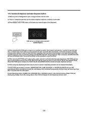
... dispensing function used . 2) There is 1 dispenser pad, this interruption. 8) Last dispensing option (CUBED ICE, CRUSHED ICE or WATER) is saved in the internal memory of refrigerator is activated allowing water dispensing. When Dispenser PAD is released, GEARED MOTOR will stop . 6) While using any dispensing function and any door of Main PCB...
... dispensing function used . 2) There is 1 dispenser pad, this interruption. 8) Last dispensing option (CUBED ICE, CRUSHED ICE or WATER) is saved in the internal memory of refrigerator is activated allowing water dispensing. When Dispenser PAD is released, GEARED MOTOR will stop . 6) While using any dispensing function and any door of Main PCB...
Owner's Manual
Page 33
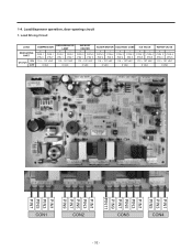
... SOLENOID CUBE ICE VALVE + - CON 3 CON 4 PIN 9 PIN 5 115 ~ 127 VAC + - Load Driving Circuit LOAD MEASURING PART ON STATUS OFF COMPRESSOR + - 1-4. CON 1 CON 1 PIN 3 PIN 7 REFRIGERATOR LAMP + - CON 1 CON 1 PIN 1 PIN 7 115 ~ 127 VAC 115 ~ 127 VAC 0 VAC 0 VAC DEFROST HEATER + - Load/dispenser operation, door opening circuit 1. CON 2 CON 2 PIN 9 PIN...
... SOLENOID CUBE ICE VALVE + - CON 3 CON 4 PIN 9 PIN 5 115 ~ 127 VAC + - Load Driving Circuit LOAD MEASURING PART ON STATUS OFF COMPRESSOR + - 1-4. CON 1 CON 1 PIN 3 PIN 7 REFRIGERATOR LAMP + - CON 1 CON 1 PIN 1 PIN 7 115 ~ 127 VAC 115 ~ 127 VAC 0 VAC 0 VAC DEFROST HEATER + - Load/dispenser operation, door opening circuit 1. CON 2 CON 2 PIN 9 PIN...


