Owner's Manual
Page 3
...Panel...21 6. Working Principles...45 2. CIRCUIT DIAGRAM...51 9. TROUBLE DIAGNOSIS...54 10. Water Valve Tubes Assembly Method 16 8. ICEMAKER AND DISPENSER WORKING PRINCIPLES AND REPAIR 45 1. Function on Icemaker...46 3. DISASSEMBLY ...6 1. Freezer Shelf...8 5. HOW TO DISASSEMBLY AND ASSEMBLY 11 1. Fan Shroud Grille...14 5. Disassemble of water supplied to Remove Swtich Lamp 13 4. Ice maker Assembly...14 6. Explanation for PCB circuit 30 7. Ice maker Troubleshooting 49 4. Door Alignment...6 2. Install Water Filter...7 3. Removing and Replacing Refrigerator door...
...Panel...21 6. Working Principles...45 2. CIRCUIT DIAGRAM...51 9. TROUBLE DIAGNOSIS...54 10. Water Valve Tubes Assembly Method 16 8. ICEMAKER AND DISPENSER WORKING PRINCIPLES AND REPAIR 45 1. Function on Icemaker...46 3. DISASSEMBLY ...6 1. Freezer Shelf...8 5. HOW TO DISASSEMBLY AND ASSEMBLY 11 1. Fan Shroud Grille...14 5. Disassemble of water supplied to Remove Swtich Lamp 13 4. Ice maker Assembly...14 6. Explanation for PCB circuit 30 7. Ice maker Troubleshooting 49 4. Door Alignment...6 2. Install Water Filter...7 3. Removing and Replacing Refrigerator door...
Owner's Manual
Page 5
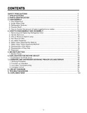
SPECIFICATIONS GENERAL FEATURES MODELS LSC27914SB /01 LSC27914SW /01 LSC27914TT /01 LSC27914ST /01 FREEZER REFRIGERATOR SPECIFICATIONS Color Dimensions Net Weight Capacity Refrigerant Climate class Rated Rating Cooling System Temperature Control Defrosting System Insulation Compressor Evaporator Condenser Lubricanting Oil Drier Capillary Tube First Defrost Defrost Cycle Desfrosting Device Anti-freezing Heater Case Material Door Material Handle Type Display Graphic Basket Lamp Shelf Tray meat Egg Bank Ice Maker Basket Lamp Shelf Black PCM Super White Titanium Stainless 36 x 33 x 70 in ...
SPECIFICATIONS GENERAL FEATURES MODELS LSC27914SB /01 LSC27914SW /01 LSC27914TT /01 LSC27914ST /01 FREEZER REFRIGERATOR SPECIFICATIONS Color Dimensions Net Weight Capacity Refrigerant Climate class Rated Rating Cooling System Temperature Control Defrosting System Insulation Compressor Evaporator Condenser Lubricanting Oil Drier Capillary Tube First Defrost Defrost Cycle Desfrosting Device Anti-freezing Heater Case Material Door Material Handle Type Display Graphic Basket Lamp Shelf Tray meat Egg Bank Ice Maker Basket Lamp Shelf Black PCM Super White Titanium Stainless 36 x 33 x 70 in ...
Owner's Manual
Page 6
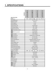
... items listed below. H Refrigerator Lamp I C J K D H L A E A M L F Use this page to the dispenser. PARTS IDENTIFICATION G A H B I Water Filter J Refrigerator Shelf K Snack Pan For storage of meat or fresh food. The locations of the features shown below may have some or all of dairy products such as butter and cheese. Note: This guide covers several different models.The refrigerator you have purchased may not match your model. A Freezer Door Rack B Automatic Icemaker The ice...
... items listed below. H Refrigerator Lamp I C J K D H L A E A M L F Use this page to the dispenser. PARTS IDENTIFICATION G A H B I Water Filter J Refrigerator Shelf K Snack Pan For storage of meat or fresh food. The locations of the features shown below may have some or all of dairy products such as butter and cheese. Note: This guide covers several different models.The refrigerator you have purchased may not match your model. A Freezer Door Rack B Automatic Icemaker The ice...
Owner's Manual
Page 7
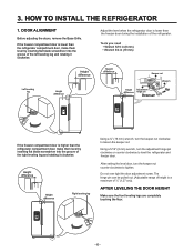
... setting the level door, turn the keeper nut counter clockwise to level the refrigerator and freezer door. AFTER LEVELING THE DOOR HEIGHT Make sure the front leveling legs are completely touching the floor. - 6 - Do not over tight the door adjustment screw. HOW TO INSTALL THE REFRIGERATOR 1. Tools you need • Wrench 5/16 in (8 mm) • Wrench 3/4 in (19 mm) Left leveling leg Height difference Height difference Height difference Keeper nut Wrench Height Adjustment Up difference hinge...
... setting the level door, turn the keeper nut counter clockwise to level the refrigerator and freezer door. AFTER LEVELING THE DOOR HEIGHT Make sure the front leveling legs are completely touching the floor. - 6 - Do not over tight the door adjustment screw. HOW TO INSTALL THE REFRIGERATOR 1. Tools you need • Wrench 5/16 in (8 mm) • Wrench 3/4 in (19 mm) Left leveling leg Height difference Height difference Height difference Keeper nut Wrench Height Adjustment Up difference hinge...
Owner's Manual
Page 8
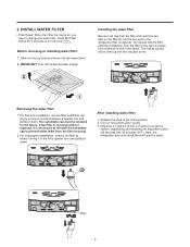
... . Replace the shelf to purge the system, depressing and releasing the dispenser button (30 seconds ON, 60 seconds OFF). Turn on the filter tip into place. Removing the water filter: 1. Open the refrigerator door and check the shelf area for leaks. A Filter - 7 - 2. You should feel the filter entering completely. For first-time installation, remove filter substitute cap (A) by slowly turning it to the left a quarter turn and pulling it to change the water filter. INSTALL WATER FILTER • Filter Reset...
... . Replace the shelf to purge the system, depressing and releasing the dispenser button (30 seconds ON, 60 seconds OFF). Turn on the filter tip into place. Removing the water filter: 1. Open the refrigerator door and check the shelf area for leaks. A Filter - 7 - 2. You should feel the filter entering completely. For first-time installation, remove filter substitute cap (A) by slowly turning it to the left a quarter turn and pulling it to change the water filter. INSTALL WATER FILTER • Filter Reset...
Owner's Manual
Page 10
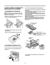
... drive … . DISASSEMBLY ICEMAKER COVER If you need acces to the Icemaker, follow these steps: • Lift the ice shelf as shown below . WATER SUPPLIED TO ICE MAKER 1) Press the test switch under the ice tray and press test switch. 4) When the ice tray rotates, the water in it out ‚ . HOW TO CONTROL THE AMOUNT OF 2) Turn on the electricity after connecting water pipe. NOTE: Use both hands to remove the ice bin to the drawing below...
... drive … . DISASSEMBLY ICEMAKER COVER If you need acces to the Icemaker, follow these steps: • Lift the ice shelf as shown below . WATER SUPPLIED TO ICE MAKER 1) Press the test switch under the ice tray and press test switch. 4) When the ice tray rotates, the water in it out ‚ . HOW TO CONTROL THE AMOUNT OF 2) Turn on the electricity after connecting water pipe. NOTE: Use both hands to remove the ice bin to the drawing below...

Owner's Manual
Page 11
... 11.0 1) The water supplying time is delivered. 2) The amount of water in the control panel. Caution: When adjusting the amount of water supplied to the icemaker. 3-2 Control the amount of water supplied, adjust step by step. Caution: • Unplug the power cord from the wall outlet and wait at 9s when the refrigerator is set at least three minutes before removing the main PWB cover. 310 Volts are...
... 11.0 1) The water supplying time is delivered. 2) The amount of water in the control panel. Caution: When adjusting the amount of water supplied to the icemaker. 3-2 Control the amount of water supplied, adjust step by step. Caution: • Unplug the power cord from the wall outlet and wait at 9s when the refrigerator is set at least three minutes before removing the main PWB cover. 310 Volts are...
Owner's Manual
Page 13
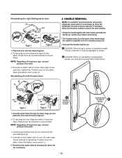
... hinge lever type. removal process is the same. 3. Insert and tighten cover screw (1). Hook tab on the back of the handle allow the handle to move the refrigerator through the lower hinge pin and place the door onto the lower hinge pin. 2. Install the grounding screw (4) and connect all the wire harnesses (3). 4. Fit top hinge (4) over hinge lever latch (7) and into the connectors. - 12 - Feed the water tubes...
... hinge lever type. removal process is the same. 3. Insert and tighten cover screw (1). Hook tab on the back of the handle allow the handle to move the refrigerator through the lower hinge pin and place the door onto the lower hinge pin. 2. Install the grounding screw (4) and connect all the wire harnesses (3). 4. Fit top hinge (4) over hinge lever latch (7) and into the connectors. - 12 - Feed the water tubes...
Owner's Manual
Page 24
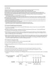
... a replacement indicator for filter cartridge on the dispenser. 2) Water filter needs replacement once six months. 3) At initial power ON, filter indicator is OFF. 4) After six months, filter indicator turns ON to reset the filter indicator, then, filter indicator turns OFF. 6) Indicator will turn ON after six months, when you need change the filter again. In initial Power On / Filter RESET Replace indicator light on , the buttons are deactivated. 4) To release from the locked state, press and hold the LOCK button for 3 seconds. The display panel shows...
... a replacement indicator for filter cartridge on the dispenser. 2) Water filter needs replacement once six months. 3) At initial power ON, filter indicator is OFF. 4) After six months, filter indicator turns ON to reset the filter indicator, then, filter indicator turns OFF. 6) Indicator will turn ON after six months, when you need change the filter again. In initial Power On / Filter RESET Replace indicator light on , the buttons are deactivated. 4) To release from the locked state, press and hold the LOCK button for 3 seconds. The display panel shows...
Owner's Manual
Page 25
... 3 hours: (1) Compressor and freezer fan (HIGH RPM) run for more than 115 seconds at the lowest temperature. However, if the refrigerator door is opened while the fan motor is operating, the fan motor will continue to increase the amount of BLDC fan motor error in the freezer, MICOM will be reduced to operate the BLDC motor, turn ON. 1-8. Control of freezing / cold storage room or Refrigerator Room are closed during defrost, ICE PLUS icon is running at...
... 3 hours: (1) Compressor and freezer fan (HIGH RPM) run for more than 115 seconds at the lowest temperature. However, if the refrigerator door is opened while the fan motor is operating, the fan motor will continue to increase the amount of BLDC fan motor error in the freezer, MICOM will be reduced to operate the BLDC motor, turn ON. 1-8. Control of freezing / cold storage room or Refrigerator Room are closed during defrost, ICE PLUS icon is running at...
Owner's Manual
Page 27
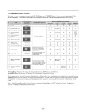
... Freezing BLDC Fan Motor 11 Abnormal Cooling BLDC Fan Motor Motor defect, hooked of lead wire to fan, contact of structures with fan, short or open of lead wire (there is indicated in the display check mode (Pressing FREEZER and ICE PLUS button at the same time more than one second). When an error occur the first 3 hours the Primary Error and Secondary Error is no errors are displayed, all display lights turn OFF except the Freezer Temperature (Trouble Code Index) indicating...
... Freezing BLDC Fan Motor 11 Abnormal Cooling BLDC Fan Motor Motor defect, hooked of lead wire to fan, contact of structures with fan, short or open of lead wire (there is indicated in the display check mode (Pressing FREEZER and ICE PLUS button at the same time more than one second). When an error occur the first 3 hours the Primary Error and Secondary Error is no errors are displayed, all display lights turn OFF except the Freezer Temperature (Trouble Code Index) indicating...
Owner's Manual
Page 29
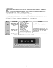
... on the main PCB of refrigerator (test switch), and the test mode will be performed. Even if pressing the test button during performance of test mode, release the test mode and display the failure code. 6. Freezer fan OFF 3. Function adjustment button is lower than +5°C, then Defrost Heater turn ON. Defrost Heater OFF 4. If Defrost Sensor is not perceived during failure code display, test mode will turn ON after maximum 2 hours irrespective of the PWB and...
... on the main PCB of refrigerator (test switch), and the test mode will be performed. Even if pressing the test button during performance of test mode, release the test mode and display the failure code. 6. Freezer fan OFF 3. Function adjustment button is lower than +5°C, then Defrost Heater turn ON. Defrost Heater OFF 4. If Defrost Sensor is not perceived during failure code display, test mode will turn ON after maximum 2 hours irrespective of the PWB and...
Owner's Manual
Page 44
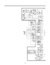
...9 KID65003AF 4 TEST 12 P02_TXD1 11 P01_RXD1_BOOT RY(1OMIH-SS-112LM) D5 IN4004 16 1 38 P42_TXD2 RY2(OZ-SS-112L1) D6 IN4004 15 2 37 P41_RXD2 AB F-DOOR SWITCH F-LAMP TMP86FS49BFG(IC1) FUSE-MELTING DISPENSER LEVER S/W CON2 SOLENOID CUBE 9 7 DISP' HEATER OPTION 5 DEF-HEATER FUSE-M1 3 1 CON3 11 AUGER MOTOR M 9 7...29 P71_AIN9 1 56K/2W 2 D10 D11 3 1R0101*2C2C37* IN4007 IN4148 2 XIN CSTS4.00MG03 OSC1 R14* 1M XOUT 3 Table 1. WATER SUPPLYING TIME CONTROL(S/W 2) SWITCH LOCATION(FIG.1) S/W1 S/W2 OFF OFF ON OFF OFF ON ON ON WORK 6.5 s 5.5 s 7.5 s 8.5 s SWITCH ON ON 12...
...9 KID65003AF 4 TEST 12 P02_TXD1 11 P01_RXD1_BOOT RY(1OMIH-SS-112LM) D5 IN4004 16 1 38 P42_TXD2 RY2(OZ-SS-112L1) D6 IN4004 15 2 37 P41_RXD2 AB F-DOOR SWITCH F-LAMP TMP86FS49BFG(IC1) FUSE-MELTING DISPENSER LEVER S/W CON2 SOLENOID CUBE 9 7 DISP' HEATER OPTION 5 DEF-HEATER FUSE-M1 3 1 CON3 11 AUGER MOTOR M 9 7...29 P71_AIN9 1 56K/2W 2 D10 D11 3 1R0101*2C2C37* IN4007 IN4148 2 XIN CSTS4.00MG03 OSC1 R14* 1M XOUT 3 Table 1. WATER SUPPLYING TIME CONTROL(S/W 2) SWITCH LOCATION(FIG.1) S/W1 S/W2 OFF OFF ON OFF OFF ON ON ON WORK 6.5 s 5.5 s 7.5 s 8.5 s SWITCH ON ON 12...
Owner's Manual
Page 46
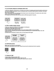
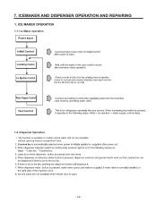
Dispenser Operation 1. The function is available in models where water and ice are available without opening freezer compartment door. ª ª - 45 - ICE MAKER OPERATION 1-1. ICEMAKER AND DISPENSER OPERATION AND REPAIRING 1. 7. Ice Maker operation 1-2.
Dispenser Operation 1. The function is available in models where water and ice are available without opening freezer compartment door. ª ª - 45 - ICE MAKER OPERATION 1-1. ICEMAKER AND DISPENSER OPERATION AND REPAIRING 1. 7. Ice Maker operation 1-2.

Owner's Manual
Page 59
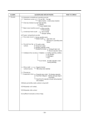
... open. / Foreign material clogging. Liquid leak. location. Small Capacity. Compressor sound inserted. Bushing Too hard. CLAIMS. 6. Not fully filled. Bad welding compressor stand(fallen). COMBO sound Capacitor noise. Pipe contacts each other. .- Sounds 1) Compressor compartment operating sounds. Stopper. Chattering sound. Clogged discharging hose. HOW TO CHECK 7. Distorted. Bad Stopper Not fit assembly. (inner diameter of drain. Condensation on door. Discharging hose Evaporation tray located...
... open. / Foreign material clogging. Liquid leak. location. Small Capacity. Compressor sound inserted. Bushing Too hard. CLAIMS. 6. Not fully filled. Bad welding compressor stand(fallen). COMBO sound Capacitor noise. Pipe contacts each other. .- Sounds 1) Compressor compartment operating sounds. Stopper. Chattering sound. Clogged discharging hose. HOW TO CHECK 7. Distorted. Bad Stopper Not fit assembly. (inner diameter of drain. Condensation on door. Discharging hose Evaporation tray located...
Owner's Manual
Page 60
.... Partly damaged. Fan motor sound. Burr. Stainless steel pipe shape in accumulator. Correct screw connection. Aged rubber seat. Narrow evaporator interval. Air intake (opposite to motor bushing assembly.) HOW TO CHECK Motor shaft contact sounds. Sound from fin evaporator and pipe during motor assembly. Condenser drain sound. Residual frost contact. Transformer sound. Normal operating sound. Fan guide contact. Unbalance. Distortion. Vibration sound. CLAIMS. 7. Back cover machine sound. Supporter disorted...
.... Partly damaged. Fan motor sound. Burr. Stainless steel pipe shape in accumulator. Correct screw connection. Aged rubber seat. Narrow evaporator interval. Air intake (opposite to motor bushing assembly.) HOW TO CHECK Motor shaft contact sounds. Sound from fin evaporator and pipe during motor assembly. Condenser drain sound. Residual frost contact. Transformer sound. Normal operating sound. Fan guide contact. Unbalance. Distortion. Vibration sound. CLAIMS. 7. Back cover machine sound. Supporter disorted...

Owner's Manual
Page 62
.... refrigerator compartment. Door is loosened during operation. Hinge loose Weak gasket adhesion. Hinge interference. Adhesion surface. CAUSES AND CHECK POINTS. Hinge-Pin tilted-Poor flatness. No grease. Storage of High. CLAIMS. 10. Not closed (faulty stopper). Bolt is open (interference by food). HOW TO CHECK 2) Odor. Faulty damper control. Poor capacity. compartment is Bad freezer compartment door opened when freezer assembly. Seal condition. Temperature of...
.... refrigerator compartment. Door is loosened during operation. Hinge loose Weak gasket adhesion. Hinge interference. Adhesion surface. CAUSES AND CHECK POINTS. Hinge-Pin tilted-Poor flatness. No grease. Storage of High. CLAIMS. 10. Not closed (faulty stopper). Bolt is open (interference by food). HOW TO CHECK 2) Odor. Faulty damper control. Poor capacity. compartment is Bad freezer compartment door opened when freezer assembly. Seal condition. Temperature of...
Owner's Manual
Page 64
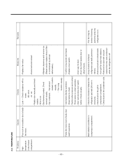
...). - 2-3. Problems Causes Checks Measures Remarks High temperature in compressor compartment. - Reconnect and reinsert. - Replace door switch. - Check the clearance between refrigerator and wall (50 mm in - Poor cool air circulation due to faulty door switch operation. - tester. 0 : short. : cut . - Fan constraint. - Confirm icing causes and repair. Faulty fan motor due to faulty - Press button to check operation. - button: Check visually. - Rotate rotor manually and check rotation. - Bad radiation conditions in the freezer...
...). - 2-3. Problems Causes Checks Measures Remarks High temperature in compressor compartment. - Reconnect and reinsert. - Replace door switch. - Check the clearance between refrigerator and wall (50 mm in - Poor cool air circulation due to faulty door switch operation. - tester. 0 : short. : cut . - Fan constraint. - Confirm icing causes and repair. Faulty fan motor due to faulty - Press button to check operation. - button: Check visually. - Rotate rotor manually and check rotation. - Bad radiation conditions in the freezer...
Owner's Manual
Page 84
... OFF Open Other Normal Service Action Go to Step 3 Check the Temperature and Resistance (Temperature Chart #2) Result 0 Ù Short OFF Open Other Normal Service Action Replace Defrost controller assembly, then, explain to customer. 4) Abnormal Defrost Sensor Error NO. Defrost Controller 3 Assembly connector Unplug connector CON 6 from Main PCB and check between Orange to step 4. Result 0 Ù Short OFF Open Other Normal Service Action Replace Product Replace Main PCB - 83 - Plug Defrost controller assembly, then...
... OFF Open Other Normal Service Action Go to Step 3 Check the Temperature and Resistance (Temperature Chart #2) Result 0 Ù Short OFF Open Other Normal Service Action Replace Defrost controller assembly, then, explain to customer. 4) Abnormal Defrost Sensor Error NO. Defrost Controller 3 Assembly connector Unplug connector CON 6 from Main PCB and check between Orange to step 4. Result 0 Ù Short OFF Open Other Normal Service Action Replace Product Replace Main PCB - 83 - Plug Defrost controller assembly, then...
Owner's Manual
Page 116
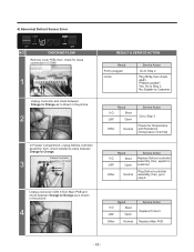
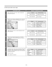
... - CHECKING FLOW Open refrigerator door, then, check manually the door S/W movement. 1 Remove cover hinge in refrigerator door, check the measurement in Door S/W DC part as is shown in the picture. 2 RESULT & SERVICE ACTION Result Tight movement Service Action Replace Door S/W Free movement Go to Step 2 Result Pressed 5 Vdc Other Released 0 Vdc Other Service Action Check in released mode Replace PCB Go to Step 3 Replace PCB Open freezer door, then, check manually the door S/W movement. 3 Remove cover hinge in freezer door, check...
... - CHECKING FLOW Open refrigerator door, then, check manually the door S/W movement. 1 Remove cover hinge in refrigerator door, check the measurement in Door S/W DC part as is shown in the picture. 2 RESULT & SERVICE ACTION Result Tight movement Service Action Replace Door S/W Free movement Go to Step 2 Result Pressed 5 Vdc Other Released 0 Vdc Other Service Action Check in released mode Replace PCB Go to Step 3 Replace PCB Open freezer door, then, check manually the door S/W movement. 3 Remove cover hinge in freezer door, check...


