User Manual
Page 2
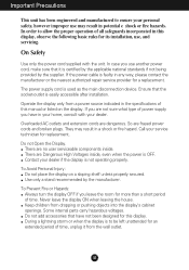
... of this display. The power supply cord is not operating properly. Overloaded AC outlets and extension cords are frayed power cords and broken plugs. Contact your dealer. Ensure that it from the wall outlet. There are no user serviceable components inside , even when the power is easily accessible after installation. To Prevent Fire or Hazards: Always turn the display OFF if you use another power cord, make sure that...
... of this display. The power supply cord is not operating properly. Overloaded AC outlets and extension cords are frayed power cords and broken plugs. Contact your dealer. Ensure that it from the wall outlet. There are no user serviceable components inside , even when the power is easily accessible after installation. To Prevent Fire or Hazards: Always turn the display OFF if you use another power cord, make sure that...

User Manual
Page 3
... or heat source. Do not press the LCD screen with anything to obtain the best image quality for your finger for a long time as this will have no impact or effect on a bed, sofa, rug, etc. On Cleaning Unplug the display before cleaning the face of the display screen. Do not use this is characteristic of the fixed-resolution LCD panel. If possible, use an aerosol...
... or heat source. Do not press the LCD screen with anything to obtain the best image quality for your finger for a long time as this will have no impact or effect on a bed, sofa, rug, etc. On Cleaning Unplug the display before cleaning the face of the display screen. Do not use this is characteristic of the fixed-resolution LCD panel. If possible, use an aerosol...
User Manual
Page 4
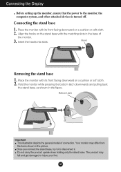
Connecting the Display Before setting up the monitor, ensure that the power to disconnect it. Bottom Latch Important This illustration depicts the general model of the monitor. 3. Your monitor may fall and get damaged or injure your foot. The product may differ from the items shown in the picture. Hook Removing the stand base 1. Once you connect the stand base, try not to the monitor, the computer system...
Connecting the Display Before setting up the monitor, ensure that the power to disconnect it. Bottom Latch Important This illustration depicts the general model of the monitor. 3. Your monitor may fall and get damaged or injure your foot. The product may differ from the items shown in the picture. Hook Removing the stand base 1. Once you connect the stand base, try not to the monitor, the computer system...
User Manual
Page 5
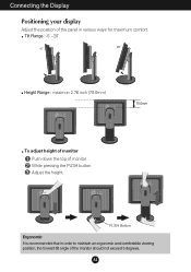
Connecting the Display Positioning your display Adjust the position of monitor While pressing the PUSH button. Tilt Range : -5˚~20˚ Height Range : maximun 2.76 inch (70.0mm) 70.0mm PUSH PUSH To adjust height of monitor Push down the top of the panel in order to maintain an ergonomic and comfortable viewing position, the forward tilt angle of the monitor should not exceed 5 degrees. A4 Adjust the height. PUSH PUSH PUSH PUSH Button Ergonomic It is recommended that in various ways for maximum comfort.
Connecting the Display Positioning your display Adjust the position of monitor While pressing the PUSH button. Tilt Range : -5˚~20˚ Height Range : maximun 2.76 inch (70.0mm) 70.0mm PUSH PUSH To adjust height of monitor Push down the top of the panel in order to maintain an ergonomic and comfortable viewing position, the forward tilt angle of the monitor should not exceed 5 degrees. A4 Adjust the height. PUSH PUSH PUSH PUSH Button Ergonomic It is recommended that in various ways for maximum comfort.
User Manual
Page 6
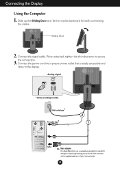
Connect the signal cable. A5 Analog signal * Varies according to model. * Wall-outlet type * PC-outlet type PUSH 2 1 PC MAC Mac adapter For Apple Macintosh use, a separate plug adapter is easily accessible and close to the display. Connect the power cord into a proper power outlet that is needed to change the 15 pin high density (3 row) D-sub VGA connector on the supplied cable to secure the connection. 3. Slide up the Sliding Door and tilt the monitor backward for...
Connect the signal cable. A5 Analog signal * Varies according to model. * Wall-outlet type * PC-outlet type PUSH 2 1 PC MAC Mac adapter For Apple Macintosh use, a separate plug adapter is easily accessible and close to the display. Connect the power cord into a proper power outlet that is needed to change the 15 pin high density (3 row) D-sub VGA connector on the supplied cable to secure the connection. 3. Slide up the Sliding Door and tilt the monitor backward for...
User Manual
Page 7
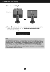
... 'AUTO' button on the OSD adjustment menu. Press button on the front switch panel to turn the power on , the 'Self Image Setting Function' is turned on . Sliding Door PUSH PUSH 5. REGLAGE AUTOMATIQUE DE LA RESOLUTION NOTE ' Self Image Setting Function'? Connecting the Display 4. If you may execute the 'FACTORY RESET' option on the front panel of the monitor. A6 Otherwise, you want to adjust the monitor while in use, or wish to optimal settings for individual input signals...
... 'AUTO' button on the OSD adjustment menu. Press button on the front switch panel to turn the power on , the 'Self Image Setting Function' is turned on . Sliding Door PUSH PUSH 5. REGLAGE AUTOMATIQUE DE LA RESOLUTION NOTE ' Self Image Setting Function'? Connecting the Display 4. If you may execute the 'FACTORY RESET' option on the front panel of the monitor. A6 Otherwise, you want to adjust the monitor while in use, or wish to optimal settings for individual input signals...
User Manual
Page 8
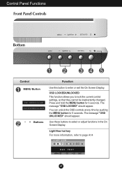
... - + MENU LightView SET/AUTO Control MENU Button OSD VERROUILLAGE OSD DEVERROUILLAGEE - + Buttons Function Use this button to page A14 LIGHT VIEW 12 DAY TEXT MENU - + SET A7 The message "OSD LOCKED" should appear. You can unlock the OSD controls at any time by pushing the MENU button for 5 seconds. LightView hot key For more information, refer to enter or exit the On Screen Display. Use these buttons to lock the current control settings, so that they cannot be inadvertently changed. OSD LOCKED/UNLOCKED...
... - + MENU LightView SET/AUTO Control MENU Button OSD VERROUILLAGE OSD DEVERROUILLAGEE - + Buttons Function Use this button to page A14 LIGHT VIEW 12 DAY TEXT MENU - + SET A7 The message "OSD LOCKED" should appear. You can unlock the OSD controls at any time by pushing the MENU button for 5 seconds. LightView hot key For more information, refer to enter or exit the On Screen Display. Use these buttons to lock the current control settings, so that they cannot be inadvertently changed. OSD LOCKED/UNLOCKED...
User Manual
Page 9
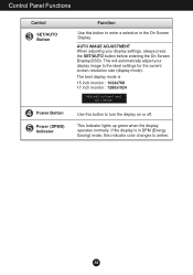
...to turn the display on or off. The best display mode is in DPM (Energy Saving) mode, this button to enter a selection in the On Screen Display. A8 This will automatically adjust your display settings, always press the SET/AUTO button before entering the On Screen Display(OSD). AUTO IMAGE ADJUSTMENT When adjusting your display image to the ideal settings for the current screen resolution size (display mode). Control Panel Functions Control SET/AUTO Button Power Button Power (DPMS) Indicator Function Use this indicator color changes to amber. This Indicator lights up green when...
...to turn the display on or off. The best display mode is in DPM (Energy Saving) mode, this button to enter a selection in the On Screen Display. A8 This will automatically adjust your display settings, always press the SET/AUTO button before entering the On Screen Display(OSD). AUTO IMAGE ADJUSTMENT When adjusting your display image to the ideal settings for the current screen resolution size (display mode). Control Panel Functions Control SET/AUTO Button Power Button Power (DPMS) Indicator Function Use this indicator color changes to amber. This Indicator lights up green when...
User Manual
Page 10
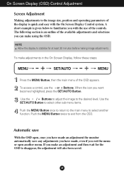
... the SET/AUTO Button. NOTE Allow the display to stabilize for the OSD to disappear, the adjustment will also been saved. When the icon you with the On Screen Display Control system. Use the - / + Buttons to adjust the image to exit from the OSD. Use the SET/AUTO Button to select other sub-menu items. Push the MENU Button once to return to the main menu to select another menu. On Screen Display (OSD) Control Adjustment Screen Adjustment Making adjustments to the image size, position and...
... the SET/AUTO Button. NOTE Allow the display to stabilize for the OSD to disappear, the adjustment will also been saved. When the icon you with the On Screen Display Control system. Use the - / + Buttons to adjust the image to exit from the OSD. Use the SET/AUTO Button to select other sub-menu items. Push the MENU Button once to return to the main menu to select another menu. On Screen Display (OSD) Control Adjustment Screen Adjustment Making adjustments to the image size, position and...
User Manual
Page 11
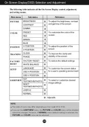
... menu Sub-menu PICTURE BRIGHTNESS CONTRAST GAMMA COLOR PRESET RED GREEN POSITION BLUE H POSITION V POSITION TRACKING CLOCK PHASE FACTORY FACTORY RESET RESET WHITE BALANCE SETUP LANGUAGE OSD H POSITION OSD V POSITION LIGHTVIEW DAY TEXT/MOVIE/PHOTO NIGHT TEXT/MOVIE/PHOTO USER1/2 NORMAL Reference To adjust the brightness, contrast and gamma of the screen To customize the color of the screen To adjust the position of the screen To improve the clarity and stability of the screen To restore the default settings To customize the screen status for a user...
... menu Sub-menu PICTURE BRIGHTNESS CONTRAST GAMMA COLOR PRESET RED GREEN POSITION BLUE H POSITION V POSITION TRACKING CLOCK PHASE FACTORY FACTORY RESET RESET WHITE BALANCE SETUP LANGUAGE OSD H POSITION OSD V POSITION LIGHTVIEW DAY TEXT/MOVIE/PHOTO NIGHT TEXT/MOVIE/PHOTO USER1/2 NORMAL Reference To adjust the brightness, contrast and gamma of the screen To customize the color of the screen To adjust the position of the screen To improve the clarity and stability of the screen To restore the default settings To customize the screen status for a user...
User Manual
Page 12
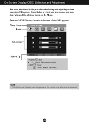
Menu Name Icons PICTURE Sub-menus Button Tip 50 50 0 MENU - + SET MENU : Exit - + : Adjust (Decrease/Increase) SET : Enter : Select another sub-menu NOTE OSD (On Screen Display) menu languages on the Menu. Press the MENU Button, then the main menu of the all items shown on the monitor may differ from the manual. Listed below are the icons, icon names, and icon descriptions of the OSD appears. On Screen Display(OSD) Selection and Adjustment You were introduced to the procedure of selecting and adjusting an item using the OSD system. A11
Menu Name Icons PICTURE Sub-menus Button Tip 50 50 0 MENU - + SET MENU : Exit - + : Adjust (Decrease/Increase) SET : Enter : Select another sub-menu NOTE OSD (On Screen Display) menu languages on the Menu. Press the MENU Button, then the main menu of the all items shown on the monitor may differ from the manual. Listed below are the icons, icon names, and icon descriptions of the OSD appears. On Screen Display(OSD) Selection and Adjustment You were introduced to the procedure of selecting and adjusting an item using the OSD system. A11
User Manual
Page 13
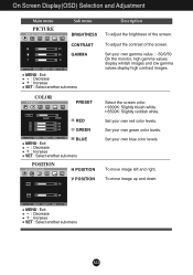
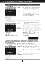
... Screen Display(OSD) Selection and Adjustment Main menu PICTURE BRIGHTNESS Sub menu BRIGHTNESS CONTRAST 50 50 GAMMA 0 MENU - + SET MENU : Exit +- : Decrease : Increase SET : Select another sub-menu COLOR PRESET PRESET 6500K 9300K 50 50 50 RED GREEN MENU - + SET BLUE MENU : Exit +- : Decrease : Increase SET : Select another sub-menu A12 To move image left and right. To adjust the contrast of the screen. Set your own red color levels. Set your own gamma value. : -50/0/50 On the monitor, high gamma values display...
... Screen Display(OSD) Selection and Adjustment Main menu PICTURE BRIGHTNESS Sub menu BRIGHTNESS CONTRAST 50 50 GAMMA 0 MENU - + SET MENU : Exit +- : Decrease : Increase SET : Select another sub-menu COLOR PRESET PRESET 6500K 9300K 50 50 50 RED GREEN MENU - + SET BLUE MENU : Exit +- : Decrease : Increase SET : Select another sub-menu A12 To move image left and right. To adjust the contrast of the screen. Set your own red color levels. Set your own gamma value. : -50/0/50 On the monitor, high gamma values display...
User Manual
Page 14
... horizontal position of the video card in the screen. OSD To adjust vertical position of the video card is an analog signal. On Screen Display(OSD) Selection and Adjustment Main menu TRACKING CLOCK Sub menu CLOCK 50 PHASE 50 MENU - + SET MENU : Exit +- : Decrease : Increase SET : Select another sub-menu FACTORY RESET FACTORY RESET FACTORY RESET YES NO WHITE BALANCE PRESET MODE MENU 1024 x 768 60Hz - + SET MENU : Exit +- : Adjust : Adjust SET : Select another sub-menu A13 or + button to provide the optimal image. If the output of the OSD V POSITION window...
... horizontal position of the video card in the screen. OSD To adjust vertical position of the video card is an analog signal. On Screen Display(OSD) Selection and Adjustment Main menu TRACKING CLOCK Sub menu CLOCK 50 PHASE 50 MENU - + SET MENU : Exit +- : Decrease : Increase SET : Select another sub-menu FACTORY RESET FACTORY RESET FACTORY RESET YES NO WHITE BALANCE PRESET MODE MENU 1024 x 768 60Hz - + SET MENU : Exit +- : Adjust : Adjust SET : Select another sub-menu A13 or + button to provide the optimal image. If the output of the OSD V POSITION window...

User Manual
Page 15
... NO USER 1 USER 2 User can preset the BRIGHTNESS, CONTRAST, GAMMA, and PRESET levels and save the YES value using the SET button and save them for later use. Menu Name LIGHT VIEW Icons 12 Sub-menu Name DAY TEXT MENU - + SET Main menu Sub menu Description LIGHTVIEW LIGHT VIEW 12 DAY NIGHT DAY TEXT MENU - + SET - + : Select another sub-menu LIGHT VIEW NORMAL This is under normal operating conditions. 12 NORMAL MENU - + SET A14 On Screen Display(OSD) Selection and Adjustment Press...
... NO USER 1 USER 2 User can preset the BRIGHTNESS, CONTRAST, GAMMA, and PRESET levels and save the YES value using the SET button and save them for later use. Menu Name LIGHT VIEW Icons 12 Sub-menu Name DAY TEXT MENU - + SET Main menu Sub menu Description LIGHTVIEW LIGHT VIEW 12 DAY NIGHT DAY TEXT MENU - + SET - + : Select another sub-menu LIGHT VIEW NORMAL This is under normal operating conditions. 12 NORMAL MENU - + SET A14 On Screen Display(OSD) Selection and Adjustment Press...
User Manual
Page 16
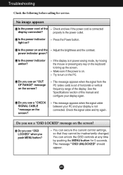
... power cord of this manual and configure your display is out of horizontal or vertical frequency range of the display. Is the power indicator light on the PC. Is the power on . Make sure if the power is in power saving mode, try again. Do you see a "CHECK SIGNAL CABLE "message on the screen? Check the signal cable and try moving the mouse or pressing any time by pushing the MENU button for service. Do you see a "OSD LOCKED...
... power cord of this manual and configure your display is out of horizontal or vertical frequency range of the display. Is the power indicator light on the PC. Is the power on . Make sure if the power is in power saving mode, try again. Do you see a "CHECK SIGNAL CABLE "message on the screen? Check the signal cable and try moving the mouse or pressing any time by pushing the MENU button for service. Do you see a "OSD LOCKED...
User Manual
Page 17
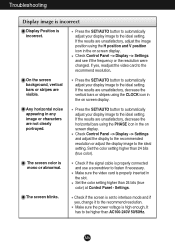
... the SET/AUTO button to automatically adjust your display image to the ideal setting. Make sure the power voltage is set to interlace mode and if yes, change it to the recommend resolution. On the screen background, vertical bars or stripes are not clearly portrayed. Check Control Panel --> Display --> Settings and adjust the display to the recommended resolution or adjust the display image to the ideal setting. Check if the signal cable is incorrect. Troubleshooting Display image is incorrect Display Position is properly connected and use a screwdriver...
... the SET/AUTO button to automatically adjust your display image to the ideal setting. Make sure the power voltage is set to interlace mode and if yes, change it to the recommend resolution. On the screen background, vertical bars or stripes are not clearly portrayed. Check Control Panel --> Display --> Settings and adjust the display to the recommended resolution or adjust the display image to the ideal setting. Check if the signal cable is incorrect. Troubleshooting Display image is incorrect Display Position is properly connected and use a screwdriver...
User Manual
Page 18
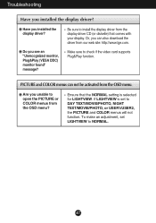
... to install the display driver from the OSD menu. Ensure that comes with your display. Do you installed the display driver? PICTURE and COLOR menus can also download the driver from the OSD menu? Troubleshooting Have you see an "Unrecognized monitor, Plug&Play (VESA DDC) monitor found" message? If LIGHTVIEW is selected for LIGHTVIEW. Or, you can not be activated from the display driver CD (or diskette) that the NORMAL setting is set LIGHTVIEW...
... to install the display driver from the OSD menu. Ensure that comes with your display. Do you installed the display driver? PICTURE and COLOR menus can also download the driver from the OSD menu? Troubleshooting Have you see an "Unrecognized monitor, Plug&Play (VESA DDC) monitor found" message? If LIGHTVIEW is selected for LIGHTVIEW. Or, you can not be activated from the display driver CD (or diskette) that the NORMAL setting is set LIGHTVIEW...
User Manual
Page 19
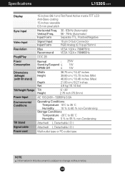
A18 Specifications L1530S H Display Sync Input Video Input Resolution Plug&Play Power Consumption Dimensions &Weight (with tilt stand) Tilt/Height Range Power Input Environmental Conditions Tilt Stand Signal cable Power cord 15 inches (38.1cm) Flat Panel Active matrix-TFT LCD Anti-Glare coating 15 inches viewable 0.3 mm pixel pitch Horizontal Freq. 30 - 63kHz (Automatic) Vertical Freq. 56 - 75Hz (Automatic) Input Form Separate TTL, Positive/Negative Signal Input Input Form 15 pin D-Sub Connector RGB Analog (0.7Vp-p/75ohm) Max Recommend VESA 1024 x 768@75Hz VESA 1024 x 768@60Hz DDC ...
A18 Specifications L1530S H Display Sync Input Video Input Resolution Plug&Play Power Consumption Dimensions &Weight (with tilt stand) Tilt/Height Range Power Input Environmental Conditions Tilt Stand Signal cable Power cord 15 inches (38.1cm) Flat Panel Active matrix-TFT LCD Anti-Glare coating 15 inches viewable 0.3 mm pixel pitch Horizontal Freq. 30 - 63kHz (Automatic) Vertical Freq. 56 - 75Hz (Automatic) Input Form Separate TTL, Positive/Negative Signal Input Input Form 15 pin D-Sub Connector RGB Analog (0.7Vp-p/75ohm) Max Recommend VESA 1024 x 768@75Hz VESA 1024 x 768@60Hz DDC ...
User Manual
Page 20
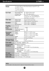
...) Separate TTL, Positive/Negative Composite TTL Positive/Negative SOG (Sync On Green) Video Input Resolution Signal Input Input Form Max Recommend 15 pin D-Sub Connector RGB Analog (0.7Vp-p/75ohm) VESA 1280 x 1024@75Hz VESA 1280 x 1024@60Hz Plug&Play DDC 2B Power Consumption Normal : 43W Stand-by/Suspend ≤ 1W DPMS Off ≤ 1W Dimensions &Weight (with tilt stand) Width Height Depth Net 39.80 cm / 15.67 inches 41.84 cm...
...) Separate TTL, Positive/Negative Composite TTL Positive/Negative SOG (Sync On Green) Video Input Resolution Signal Input Input Form Max Recommend 15 pin D-Sub Connector RGB Analog (0.7Vp-p/75ohm) VESA 1280 x 1024@75Hz VESA 1280 x 1024@60Hz Plug&Play DDC 2B Power Consumption Normal : 43W Stand-by/Suspend ≤ 1W DPMS Off ≤ 1W Dimensions &Weight (with tilt stand) Width Height Depth Net 39.80 cm / 15.67 inches 41.84 cm...
User Manual
Page 23
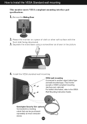
... to a locking cable that can be purchased separately at most computer stores A22 PUSH 2. Install the VESA standrad wall mounting. Please the monitor on a piece of cloth or other soft surface with the front side facing downward. 3. optional Connected to the VESA Wall Mounting Instruction Guide. Separate the stand base using a screwdriver as shown in the picture. 4. VESA wall mounting Connected to Install the VESA Standard wall mounting This monitor meets VESA-compliant mounting interface pad specifications. 1. Remove the Sliding...
... to a locking cable that can be purchased separately at most computer stores A22 PUSH 2. Install the VESA standrad wall mounting. Please the monitor on a piece of cloth or other soft surface with the front side facing downward. 3. optional Connected to the VESA Wall Mounting Instruction Guide. Separate the stand base using a screwdriver as shown in the picture. 4. VESA wall mounting Connected to Install the VESA Standard wall mounting This monitor meets VESA-compliant mounting interface pad specifications. 1. Remove the Sliding...


