Owner's Manual (English)
Page 1
Keep the User's Guide(CD) in an accessible place for support. Have the model and serial number ready when calling for furture reference. User's Guide L1718S LCD Computer Monitor Make sure to read the Important Precautions before using this product.
Keep the User's Guide(CD) in an accessible place for support. Have the model and serial number ready when calling for furture reference. User's Guide L1718S LCD Computer Monitor Make sure to read the Important Precautions before using this product.
Owner's Manual (English)
Page 4
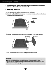
Make sure you push it until you hear it could damage the stand. Once assembled take the monitor up the monitor, ensure that the power to the monitor, the computer system, and other attached devices is turned off. A3 REAR FRONT REAR FRONT REAR REAR Connecting the Display Before setting up carefully and .... 4. Do not carry the product upside down holding only the stand base. The product may fall and get damaged or injure your foot. Place the monitor with its front facing downward on a soft cloth. 2.
Make sure you push it until you hear it could damage the stand. Once assembled take the monitor up the monitor, ensure that the power to the monitor, the computer system, and other attached devices is turned off. A3 REAR FRONT REAR FRONT REAR REAR Connecting the Display Before setting up carefully and .... 4. Do not carry the product upside down holding only the stand base. The product may fall and get damaged or injure your foot. Place the monitor with its front facing downward on a soft cloth. 2.
Owner's Manual (English)
Page 5
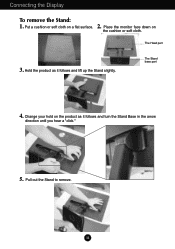
The Head part 3. The Stand base part 4. Place the monitor face down on a flat surface. Change your hold on the product as it follows and turn the Stand Base in the arrow direction until you hear a "click." 5. A4 Pull out the Stand to remove. Connecting the Display To remove the Stand: 1. 2. Hold the product as it follows and lift up the Stand slightly. Put a cushion or soft cloth on the cushion or soft cloth.
The Head part 3. The Stand base part 4. Place the monitor face down on a flat surface. Change your hold on the product as it follows and turn the Stand Base in the arrow direction until you hear a "click." 5. A4 Pull out the Stand to remove. Connecting the Display To remove the Stand: 1. 2. Hold the product as it follows and lift up the Stand slightly. Put a cushion or soft cloth on the cushion or soft cloth.
Owner's Manual (English)
Page 7
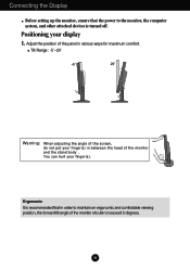
... computer system, and other attached devices is recommended that the power to maintain an ergonomic and comfortable viewing position, the forward tilt angle of the monitor and the stand body . A6 Tilt Range : -5˚~20˚ 20 Warning: When adjusting the angle of the screen, do not put your finger(s) in.... You can hurt your display 1. Ergonomic It is turned off. Positioning your finger(s). Adjust the position of the panel in between the head of the monitor should not exceed 5 degrees.
... computer system, and other attached devices is recommended that the power to maintain an ergonomic and comfortable viewing position, the forward tilt angle of the monitor and the stand body . A6 Tilt Range : -5˚~20˚ 20 Warning: When adjusting the angle of the screen, do not put your finger(s) in.... You can hurt your display 1. Ergonomic It is turned off. Positioning your finger(s). Adjust the position of the panel in between the head of the monitor should not exceed 5 degrees.
Owner's Manual (English)
Page 8
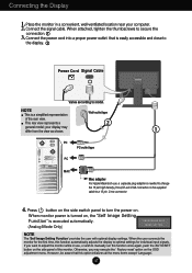
... 4. NOTE This is needed to change the 15 pin high density (3 row) D-sub VGA connector on the supplied cable to adjust the monitor while in a convenient, well-ventilated location near your display may execute the ' Factory reset' option on the side panel of the rear view... the first time, this option initializes all the menu items except 'Language'. A7 Place the monitor in use , a separate plug adapter is a simplified representation Wall-outlet type of the monitor. This rear view represents a 2 general model; However, be aware that is executed automatically. (Analog Mode ...
... 4. NOTE This is needed to change the 15 pin high density (3 row) D-sub VGA connector on the supplied cable to adjust the monitor while in a convenient, well-ventilated location near your display may execute the ' Factory reset' option on the side panel of the rear view... the first time, this option initializes all the menu items except 'Language'. A7 Place the monitor in use , a separate plug adapter is a simplified representation Wall-outlet type of the monitor. This rear view represents a 2 general model; However, be aware that is executed automatically. (Analog Mode ...
Owner's Manual (English)
Page 10
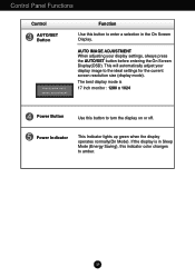
... enter a selection in the On Screen Display. Power Indicator This Indicator lights up green when the display operates normally(On Mode). If the display is 17 inch monitor : 1280 x 1024 Power Button Use this button to the ideal settings for the current screen resolution size (display mode). Control Panel Functions Control AUTO...
... enter a selection in the On Screen Display. Power Indicator This Indicator lights up green when the display operates normally(On Mode). If the display is 17 inch monitor : 1280 x 1024 Power Button Use this button to the ideal settings for the current screen resolution size (display mode). Control Panel Functions Control AUTO...
Owner's Manual (English)
Page 13
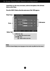
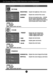
Menu Name PICTURE Icons Sub-menus Button Tip MENU : Exit : Adjust (Decrease/Increase) SET : Enter : Select another sub-menu NOTE OSD (On Screen Display) menu languages on the Menu. Press the MENU Button, then the main menu of the all items shown on the monitor may differ from the manual. On Screen Display(OSD) Selection and Adjustment Listed below are the icons, icon names, and icon descriptions of the OSD appears. A12
Menu Name PICTURE Icons Sub-menus Button Tip MENU : Exit : Adjust (Decrease/Increase) SET : Enter : Select another sub-menu NOTE OSD (On Screen Display) menu languages on the Menu. Press the MENU Button, then the main menu of the all items shown on the monitor may differ from the manual. On Screen Display(OSD) Selection and Adjustment Listed below are the icons, icon names, and icon descriptions of the OSD appears. A12
Owner's Manual (English)
Page 14
... the screen image left and right. GAMMA MENU : Exit : Decrease : Increase SET : Select another sub-menu Set your own gamma value. : -50/0/50 On the monitor, high gamma values display whitish images and low gamma values display high contrast images.
... the screen image left and right. GAMMA MENU : Exit : Decrease : Increase SET : Select another sub-menu Set your own gamma value. : -50/0/50 On the monitor, high gamma values display whitish images and low gamma values display high contrast images.
Owner's Manual (English)
Page 15
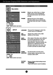
... displayed. A14 SETUP SETUP MENU - WHITE BALANCE If the output of the video card is adjusted to fit into the standard output level of the monitor to remove any vertical bars or stripes visible on the screen. This item allows you to ON or OFF. POWER MENU - + SET INDICATOR MENU : Exit...
... displayed. A14 SETUP SETUP MENU - WHITE BALANCE If the output of the video card is adjusted to fit into the standard output level of the monitor to remove any vertical bars or stripes visible on the screen. This item allows you to ON or OFF. POWER MENU - + SET INDICATOR MENU : Exit...
Owner's Manual (English)
Page 18
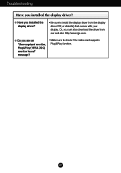
Or, you installed the display driver? • Be sure to check if the video card supports Plug&Play function. G Do you installed the display driver? A17 Troubleshooting Have you see an "Unrecognized monitor, Plug&Play (VESA DDC) monitor found" message? • Make sure to install the display driver from our web site: http://www.lge.com. G Have you can also download the driver from the display driver CD (or diskette) that comes with your display.
Or, you installed the display driver? • Be sure to check if the video card supports Plug&Play function. G Do you installed the display driver? A17 Troubleshooting Have you see an "Unrecognized monitor, Plug&Play (VESA DDC) monitor found" message? • Make sure to install the display driver from our web site: http://www.lge.com. G Have you can also download the driver from the display driver CD (or diskette) that comes with your display.
Owner's Manual (English)
Page 21
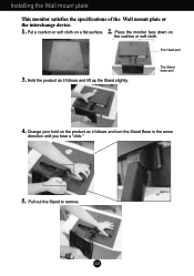
Hold the product as it follows and lift up the Stand slightly. Put a cushion or soft cloth on the cushion or soft cloth. The Stand base part 4. Change your hold on the product as it follows and turn the Stand Base in the arrow direction until you hear a "click." 5. A20 The Head part 3. Pull out the Stand to remove. Installing the Wall mount plate This monitor satisfies the specifications of the Wall mount plate or the interchange device. 1. 2. Place the monitor face down on a flat surface.
Hold the product as it follows and lift up the Stand slightly. Put a cushion or soft cloth on the cushion or soft cloth. The Stand base part 4. Change your hold on the product as it follows and turn the Stand Base in the arrow direction until you hear a "click." 5. A20 The Head part 3. Pull out the Stand to remove. Installing the Wall mount plate This monitor satisfies the specifications of the Wall mount plate or the interchange device. 1. 2. Place the monitor face down on a flat surface.
Owner's Manual (English)
Page 22
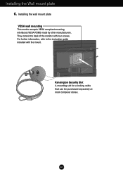
Installing the Wall mount plate 6. They connect to the instruction guide included with four screws. A21 Kensington Security Slot A mounting slot for a locking cable that can be purchased separately at most computer stores. For further information, refer to back of the monitor with the mount. Installing the wall mount plate VESA wall mounting This monitor accepts VESA compliant mounting interfaces (VESA FDMI) made by other manufacturers.
Installing the Wall mount plate 6. They connect to the instruction guide included with four screws. A21 Kensington Security Slot A mounting slot for a locking cable that can be purchased separately at most computer stores. For further information, refer to back of the monitor with the mount. Installing the wall mount plate VESA wall mounting This monitor accepts VESA compliant mounting interfaces (VESA FDMI) made by other manufacturers.
Service Manual
Page 1
Website:http://biz.LGservice.com E-mail:http://www.LGEservice.com/techsup.html COLOR MONITOR SERVICE MANUAL CHASSIS NO. : MODEL: L1718S (L1718S-SNQ/L1718S-BNQ.Axx*EP) xx* means sales region and Module (xxK : INNOLUX, xxB : CPT) CAUTION BEFORE SERVICING THE UNIT, READ THE SAFETY PRECAUTIONS IN THIS MANUAL. *To apply the MSTAR Chip.
Website:http://biz.LGservice.com E-mail:http://www.LGEservice.com/techsup.html COLOR MONITOR SERVICE MANUAL CHASSIS NO. : MODEL: L1718S (L1718S-SNQ/L1718S-BNQ.Axx*EP) xx* means sales region and Module (xxK : INNOLUX, xxB : CPT) CAUTION BEFORE SERVICING THE UNIT, READ THE SAFETY PRECAUTIONS IN THIS MANUAL. *To apply the MSTAR Chip.

Service Manual
Page 3
... of the inverter circuit. These parts are pressed cause short and may burn or take fire. • Be careful while tilting and rotating the monitor to avoid pinching hand(s) • Must mount the module using mounting holes arranged in four corners. • Do not press on the panel ... pen as WATER PIPE, CONDUIT etc. 1.5 Kohm/10W 3 PRECAUTION WARNING FOR THE SAFETY-RELATED COMPONENT. • There are some special components used in LCD monitor that are grounded through wrist band. • Do not leave the module in high temperature and in areas of high humidity for safety.
... of the inverter circuit. These parts are pressed cause short and may burn or take fire. • Be careful while tilting and rotating the monitor to avoid pinching hand(s) • Must mount the module using mounting holes arranged in four corners. • Do not press on the panel ... pen as WATER PIPE, CONDUIT etc. 1.5 Kohm/10W 3 PRECAUTION WARNING FOR THE SAFETY-RELATED COMPONENT. • There are some special components used in LCD monitor that are grounded through wrist band. • Do not leave the module in high temperature and in areas of high humidity for safety.

Service Manual
Page 12
... circuit included a line-filter, across line capacitor and of course the primary protection fuse. 2. Input rectifier and filter. Energy Transfer. This part function is also monitor by this part. 5. This part contains of EMI components to achive the dc output stablize, and also the over power protection is to collect the...
... circuit included a line-filter, across line capacitor and of course the primary protection fuse. 2. Input rectifier and filter. Energy Transfer. This part function is also monitor by this part. 5. This part contains of EMI components to achive the dc output stablize, and also the over power protection is to collect the...
Service Manual
Page 13
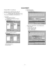
f) Click Exit button. 13 This program is available to "c:\WINNT\system32\drivers" folder b) Run Userport.exe c) Remove all default number d) Add 300-3FF 2) Edit Week of Manufacture, Year of Manufacture, Serial Number a) Input User Info Data b) Click "Update" button c) Click " Write" button e) Click Start button. Port Setup a) Copy "UserPort.sys" file to LCD Monitor only. 2. ADJUSTMENT Windows EDID V1.0 User Manual Operating System: MS Windows 98, 2000, XP Port Setup: Windows 98 => Don't need setup Windows 2000, XP => Need to Port Setup. EDID Read & Write 1) Run WinEDID.exe 1.
f) Click Exit button. 13 This program is available to "c:\WINNT\system32\drivers" folder b) Run Userport.exe c) Remove all default number d) Add 300-3FF 2) Edit Week of Manufacture, Year of Manufacture, Serial Number a) Input User Info Data b) Click "Update" button c) Click " Write" button e) Click Start button. Port Setup a) Copy "UserPort.sys" file to LCD Monitor only. 2. ADJUSTMENT Windows EDID V1.0 User Manual Operating System: MS Windows 98, 2000, XP Port Setup: Windows 98 => Don't need setup Windows 2000, XP => Need to Port Setup. EDID Read & Write 1) Run WinEDID.exe 1.
Service Manual
Page 14
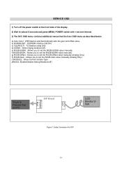
... set the R/G/B-Gain value manually.(Analog Only) i) MODULE : Show Current module Type j)RS232: Enable/Disable Debug Mode(on PC ISP Board D-SUB 15PIN Parallel Port LCD Monitor DSub Figure 1.Cable Connection For ISP 14 SERVICE OSD 1) Turn off the power switch at the front side of the display. 2) Wait for about 5 seconds...
... set the R/G/B-Gain value manually.(Analog Only) i) MODULE : Show Current module Type j)RS232: Enable/Disable Debug Mode(on PC ISP Board D-SUB 15PIN Parallel Port LCD Monitor DSub Figure 1.Cable Connection For ISP 14 SERVICE OSD 1) Turn off the power switch at the front side of the display. 2) Wait for about 5 seconds...


