
Owners Manual
Page 1
LCD MONITOR MODEL E1911T E1911S E2211T E2211S E2411T www.lg.com ENGLISH OWNER'S MANUAL LCD MONITOR Please read this manual carefully before operating your set and retain it for future reference.
LCD MONITOR MODEL E1911T E1911S E2211T E2211S E2411T www.lg.com ENGLISH OWNER'S MANUAL LCD MONITOR Please read this manual carefully before operating your set and retain it for future reference.
Owners Manual
Page 5
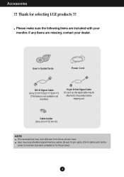
... holder (Only E1911T/E1911S) NOTE This accessories may look different from those shown here. User's Guide/Cards Power Cord DVI-D Signal Cable (Only E1911T/E2211T/E2411T) (This feature is not available in all countries.) 15-pin D-Sub Signal Cable (To set it up, this signal cable may be attached to maintain...
... holder (Only E1911T/E1911S) NOTE This accessories may look different from those shown here. User's Guide/Cards Power Cord DVI-D Signal Cable (Only E1911T/E2211T/E2411T) (This feature is not available in all countries.) 15-pin D-Sub Signal Cable (To set it up, this signal cable may be attached to maintain...
Owners Manual
Page 6
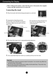
...Tie down holding only the stand base. Connecting the Display Before setting up carefully and face the front side. Once assembled take the monitor up the monitor, ensure that the power to perpendicularity direction. . 5. Do not carry the product upside down the base lock to the... illustration depicts the general model of connection. Connecting the stand 1. Make sure you push it until you hear it "click". Hinge Body 3. Your monitor may fall and get damaged or injure your foot. 5 Stand Body Stand Body Stand Base 4. Assemble the Stand Body into the Stand Body in ...
...Tie down holding only the stand base. Connecting the Display Before setting up carefully and face the front side. Once assembled take the monitor up the monitor, ensure that the power to perpendicularity direction. . 5. Do not carry the product upside down the base lock to the... illustration depicts the general model of connection. Connecting the stand 1. Make sure you push it until you hear it "click". Hinge Body 3. Your monitor may fall and get damaged or injure your foot. 5 Stand Body Stand Body Stand Base 4. Assemble the Stand Body into the Stand Body in ...

Owners Manual
Page 7
Put a cushion or soft cloth on the cushion or soft cloth. 3. If you can't release the stand base even the locking knob is at a release position, Please push the indicated knob down and retry it in the arrow direction. . Change your lock on the product as it follows and turn it . 6 Connecting the Display Disassembling the stand 1. Place the monitor face Down on aflat surface. 2.
Put a cushion or soft cloth on the cushion or soft cloth. 3. If you can't release the stand base even the locking knob is at a release position, Please push the indicated knob down and retry it in the arrow direction. . Change your lock on the product as it follows and turn it . 6 Connecting the Display Disassembling the stand 1. Place the monitor face Down on aflat surface. 2.
Owners Manual
Page 9
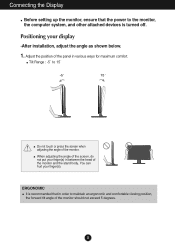
...for maximum comfort. ERGONOMIC It is recommended that the power to the monitor, the computer system, and other attached devices is turned off. Adjust the position of the monitor. You can hurt your finger(s) in between the head of the monitor and the stand body. When adjusting the angle of the screen, ...do not put your finger(s). Positioning your display -After installation, adjust the angle as shown below. 1. Connecting the Display Before setting up the monitor, ensure that in order to maintain an ergonomic and comfortable viewing position, the forward tilt angle of the...
...for maximum comfort. ERGONOMIC It is recommended that the power to the monitor, the computer system, and other attached devices is turned off. Adjust the position of the monitor. You can hurt your finger(s) in between the head of the monitor and the stand body. When adjusting the angle of the screen, ...do not put your finger(s). Positioning your display -After installation, adjust the angle as shown below. 1. Connecting the Display Before setting up the monitor, ensure that in order to maintain an ergonomic and comfortable viewing position, the forward tilt angle of the...
Owners Manual
Page 10
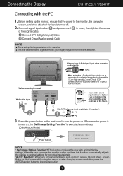
...AUTO function button to a 15 pin 2 row connector. Connect the signal input cable and tighten it up the monitor, ensure that the power to model. When monitor power is turned on, the 'Self Image Setting Function' is a simplified representation of the signal cable. When ... computer system, and other attached devices is not available in all countries.) 3. Connecting the Display E1911T/E2211T/E2411T Connecting with optimal display settings.When the user connects the monitor for Macintosh Mac adapter : For Apple Macintosh use, a separate plug adapter is needed to change the 15...
...AUTO function button to a 15 pin 2 row connector. Connect the signal input cable and tighten it up the monitor, ensure that the power to model. When monitor power is turned on, the 'Self Image Setting Function' is a simplified representation of the signal cable. When ... computer system, and other attached devices is not available in all countries.) 3. Connecting the Display E1911T/E2211T/E2411T Connecting with optimal display settings.When the user connects the monitor for Macintosh Mac adapter : For Apple Macintosh use, a separate plug adapter is needed to change the 15...
Owners Manual
Page 11
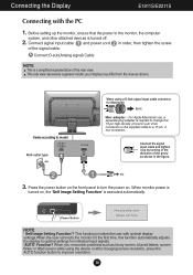
...changing screen resolution, press the AUTO function button to improve resolution. 10 Connect the signal input cable and tighten it up the monitor, ensure that the power to the monitor, the computer system, and other attached devices is executed automatically. A Connect D-sub(Analog signal) Cable NOTE This is a ...the rear view. Power Button NOTE ' Self Image Setting Function'? Connect signal input cable 1 and power cord 2 in the figure. 3. When monitor power is turned on . Connecting the Display E1911S/E2211S Connecting with optimal display settings.When the user connects the...
...changing screen resolution, press the AUTO function button to improve resolution. 10 Connect the signal input cable and tighten it up the monitor, ensure that the power to the monitor, the computer system, and other attached devices is executed automatically. A Connect D-sub(Analog signal) Cable NOTE This is a ...the rear view. Power Button NOTE ' Self Image Setting Function'? Connect signal input cable 1 and power cord 2 in the figure. 3. When monitor power is turned on . Connecting the Display E1911S/E2211S Connecting with optimal display settings.When the user connects the...
Owners Manual
Page 14
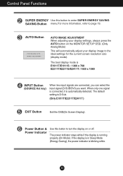
... image to page 19. The best display mode is D-Sub. (Only E1911T/E2211T/E2411T ) EXIT Button Exit the OSD(On Screen Display). The default setting is E1911T/E1911S : 1366 x 768 E2211T/E2211S/E2411T: 1920 x 1080 INPUT Button (SOURCE Hot key) When two input signals are connected..., you can select the input signal (D-SUB/DVI) you want. The power indicator stays white if the display is running properly (On Mode). Control Panel Functions SUPER ENERGY Use this button to turn the display on the MONITOR...
... image to page 19. The best display mode is D-Sub. (Only E1911T/E2211T/E2411T ) EXIT Button Exit the OSD(On Screen Display). The default setting is E1911T/E1911S : 1366 x 768 E2211T/E2211S/E2411T: 1920 x 1080 INPUT Button (SOURCE Hot key) When two input signals are connected..., you can select the input signal (D-SUB/DVI) you want. The power indicator stays white if the display is running properly (On Mode). Control Panel Functions SUPER ENERGY Use this button to turn the display on the MONITOR...

Owners Manual
Page 17
Press the MENU Button, then the main menu of selecting and adjusting an item using the OSD system. Menu Name Icons Submenus Exit Adjust (Decrease/Increase) Select another sub-menu Restart to the procedure of the OSD appears. On Screen Display(OSD) Selection and Adjustment You were introduced to select sub-menu Button Tip NOTE OSD (On Screen Display) menu languages on the Menu. Listed below are the icons, icon names, and icon descriptions of the all items shown on the monitor may differ from the manual. 16
Press the MENU Button, then the main menu of selecting and adjusting an item using the OSD system. Menu Name Icons Submenus Exit Adjust (Decrease/Increase) Select another sub-menu Restart to the procedure of the OSD appears. On Screen Display(OSD) Selection and Adjustment You were introduced to select sub-menu Button Tip NOTE OSD (On Screen Display) menu languages on the Menu. Listed below are the icons, icon names, and icon descriptions of the all items shown on the monitor may differ from the manual. 16

Owners Manual
Page 18
... mode according to cool color temperature. ORIGINAL Change the input image signal ratio to original. * This function works only if input resolution is lower than monitor ratio (16:9). BLUE Set your own green color levels. RED Set your own red color levels. On Screen Display(OSD) Selection and Adjustment Main menu...
... mode according to cool color temperature. ORIGINAL Change the input image signal ratio to original. * This function works only if input resolution is lower than monitor ratio (16:9). BLUE Set your own green color levels. RED Set your own red color levels. On Screen Display(OSD) Selection and Adjustment Main menu...

Owners Manual
Page 20
On Screen Display(OSD) Selection and Adjustment You were introduced to select sub-menu Button Tip NOTE OSD (On Screen Display) menu languages on the Menu. Press the SUPER ENERGY SAVING Button, then the main menu of the all items shown on the monitor may differ from the manual. 19 Menu Name Icons Sub-menus Exit Move Restart to the procedure of selecting and adjusting an item using the OSD system. Listed below are the icons, icon names, and icon descriptions of the OSD appears.
On Screen Display(OSD) Selection and Adjustment You were introduced to select sub-menu Button Tip NOTE OSD (On Screen Display) menu languages on the Menu. Press the SUPER ENERGY SAVING Button, then the main menu of the all items shown on the monitor may differ from the manual. 19 Menu Name Icons Sub-menus Exit Move Restart to the procedure of selecting and adjusting an item using the OSD system. Listed below are the icons, icon names, and icon descriptions of the OSD appears.
Owners Manual
Page 21
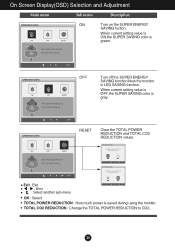
... is LED SAVING function. TOTAL CO2 REDUCTION : Change the TOTAL POWER REDUCTION to CO2. 20 OFF Turn off the SUPER ENERGY SAVING function.Now the monitor is gray. Exit : Exit , : Move : Select another sub-menu OK : Select TOTAL POWER REDUCTION : How much power is green. RESET Clear the TOTAL POWER... REDUCTION and TOTAL CO2 REDUCTION values. When current setting value is ON,the SUPER SAVING color is saved during using the monitor. On Screen Display(OSD) Selection and Adjustment Main menu Sub menu Description ON Turn on the SUPER ENERGY SAVING fuction.
... is LED SAVING function. TOTAL CO2 REDUCTION : Change the TOTAL POWER REDUCTION to CO2. 20 OFF Turn off the SUPER ENERGY SAVING function.Now the monitor is gray. Exit : Exit , : Move : Select another sub-menu OK : Select TOTAL POWER REDUCTION : How much power is green. RESET Clear the TOTAL POWER... REDUCTION and TOTAL CO2 REDUCTION values. When current setting value is ON,the SUPER SAVING color is saved during using the monitor. On Screen Display(OSD) Selection and Adjustment Main menu Sub menu Description ON Turn on the SUPER ENERGY SAVING fuction.
Owners Manual
Page 25
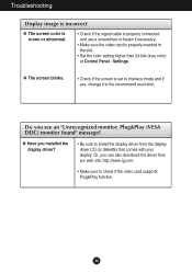
... supports Plug&Play function. 24 Or, you installed the display driver? • Be sure to install the display driver from our web site: http://www.lg.com. • Make sure to the recommend resolution. Do you see an "Unrecognized monitor, Plug&Play (VESA DDC...
... supports Plug&Play function. 24 Or, you installed the display driver? • Be sure to install the display driver from our web site: http://www.lg.com. • Make sure to the recommend resolution. Do you see an "Unrecognized monitor, Plug&Play (VESA DDC...
Owners Manual
Page 32
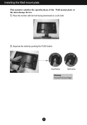
Good Position Bad Position Warning: You can hurt your finger. 31 Installing the Wall mount plate This monitor satisfies the specifications of the Wall mount plate or the interchange device. 1. Place the monitor with its front facing downward on a soft cloth. 2. Separate the stand by pushing the PUSH button.
Good Position Bad Position Warning: You can hurt your finger. 31 Installing the Wall mount plate This monitor satisfies the specifications of the Wall mount plate or the interchange device. 1. Place the monitor with its front facing downward on a soft cloth. 2. Separate the stand by pushing the PUSH button.


