Owner's Manual
Page 2
... repair service provider for this manual or listed on the product screen. Some internal parts carry hazardous voltages. On Safety Use only the power cord supplied with your dealer. In case you have not been designed for a replacement. Keep children from the wall outlet. It can cause injury to human, problem to product and damage the display. To Prevent Fire or Hazards: Always turn the display...
... repair service provider for this manual or listed on the product screen. Some internal parts carry hazardous voltages. On Safety Use only the power cord supplied with your dealer. In case you have not been designed for a replacement. Keep children from the wall outlet. It can cause injury to human, problem to product and damage the display. To Prevent Fire or Hazards: Always turn the display...

Owner's Manual
Page 3
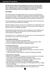
... a fixed image on the product. Important Precautions On Installation Do not allow the release of heat generated during operation. Place the display in a built-in a fire hazard. Place the display near water such as Red, Green or Blue spots on a bed, sofa, rug, etc. Make sure to use the recommended resolution to allow anything hard as this display near or over the power cord...
... a fixed image on the product. Important Precautions On Installation Do not allow the release of heat generated during operation. Place the display in a built-in a fire hazard. Place the display near water such as Red, Green or Blue spots on a bed, sofa, rug, etc. Make sure to use the recommended resolution to allow anything hard as this display near or over the power cord...
Owner's Manual
Page 6
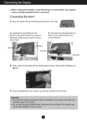
... downward on the back of connection. Use a coin on a soft cloth. 2. Connecting the stand 1. Assemble the Stand Base(Front, Rear) into the product in the correct direction as shown in the picture. Important This illustration depicts the general model of the stand base and turn the screw clockwise to the monitor, the computer system, and other attached devices is turned off. Stand Body Hinge Body Stand Body Stand Base 4.
... downward on the back of connection. Use a coin on a soft cloth. 2. Connecting the stand 1. Assemble the Stand Base(Front, Rear) into the product in the correct direction as shown in the picture. Important This illustration depicts the general model of the stand base and turn the screw clockwise to the monitor, the computer system, and other attached devices is turned off. Stand Body Hinge Body Stand Body Stand Base 4.
Owner's Manual
Page 7
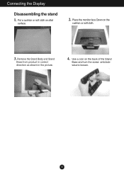
Connecting the Display Disassembling the stand 1. Place the monitor face Down on the back of the Stand Base and turn the screw anticlock- Use a coin on the cushion or soft cloth. 3. Put a cushion or soft cloth on aflat surface. 2. wise to loosen. 6 Remove the Stand Body and Stand Base from product in correct direction as shown in the picture. 4.
Connecting the Display Disassembling the stand 1. Place the monitor face Down on the back of the Stand Base and turn the screw anticlock- Use a coin on the cushion or soft cloth. 3. Put a cushion or soft cloth on aflat surface. 2. wise to loosen. 6 Remove the Stand Body and Stand Base from product in correct direction as shown in the picture. 4.

Owner's Manual
Page 8
... viewing position, the forward tilt angle of the monitor should not exceed 5 degrees. 7 When adjusting the angle of the screen, do not put your finger(s) in various ways for maximum comfort. ERGONOMIC It is turned off. Adjust the position of the panel in between the head of the monitor and the stand body. Positioning your finger(s). Connecting the Display Before setting up the monitor, ensure that the power...
... viewing position, the forward tilt angle of the monitor should not exceed 5 degrees. 7 When adjusting the angle of the screen, do not put your finger(s) in various ways for maximum comfort. ERGONOMIC It is turned off. Adjust the position of the panel in between the head of the monitor and the stand body. Positioning your finger(s). Connecting the Display Before setting up the monitor, ensure that the power...

Owner's Manual
Page 9
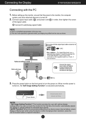
... Mac adapter : For Apple Macintosh use, a separate plug adapter is turned off. 2. This rear view represents a general model; Wall-outlet type When using the device or after changing screen resolution, press the AUTO function button to a 15 pin 2 row connector. Before setting up by turning in the direction of the signal cable. A Connect DVI-D(Digital signal) Cable B Connect D-sub(Analog signal) Cable NOTE This is executed automatically. (Only Analog Mode) Power Button NOTE ' Self Image Setting Function'? Connect the signal input cable and tighten it up the monitor, ensure...
... Mac adapter : For Apple Macintosh use, a separate plug adapter is turned off. 2. This rear view represents a general model; Wall-outlet type When using the device or after changing screen resolution, press the AUTO function button to a 15 pin 2 row connector. Before setting up by turning in the direction of the signal cable. A Connect DVI-D(Digital signal) Cable B Connect D-sub(Analog signal) Cable NOTE This is executed automatically. (Only Analog Mode) Power Button NOTE ' Self Image Setting Function'? Connect the signal input cable and tighten it up the monitor, ensure...
Owner's Manual
Page 10
...Sub signal input cable connector for individual input signals. 'AUTO' Function? Wall-outlet type Mac adapter : For Apple Macintosh use, a separate plug adapter is needed to change the 15 pin high density (3 row) D-sub VGA connector on the supplied cable to turn the power on , the 'Self Image Setting Function' is a simplified representation of the signal cable. Power Button NOTE ' Self Image Setting Function'? This rear view represents a general model; Connecting the Display E1941S/E2041S/E2241S Connecting with optimal display settings.When the user connects the monitor for...
...Sub signal input cable connector for individual input signals. 'AUTO' Function? Wall-outlet type Mac adapter : For Apple Macintosh use, a separate plug adapter is needed to change the 15 pin high density (3 row) D-sub VGA connector on the supplied cable to turn the power on , the 'Self Image Setting Function' is a simplified representation of the signal cable. Power Button NOTE ' Self Image Setting Function'? This rear view represents a general model; Connecting the Display E1941S/E2041S/E2241S Connecting with optimal display settings.When the user connects the monitor for...

Owner's Manual
Page 12
... screen resolution size (display mode). The default setting is blinking blue. 11 If the display is in Sleep Mode,the power indicator is D-Sub. (Only E1941T/E2041T/E2241T/E2341T/E2441T ) EXIT Button Exit the OSD(On Screen Display). The power indicator stays blue if the display is E1941T/E1941S : 1366 x 768 E2041T/E2041S : 1600 x 900 E2241T/E2241S/E2341T/E2441T : 1920 x 1080 INPUT Button (SOURCE Hot key) When two input signals are connected, you can select the input signal (D-SUB/DVI...
... screen resolution size (display mode). The default setting is blinking blue. 11 If the display is in Sleep Mode,the power indicator is D-Sub. (Only E1941T/E2041T/E2241T/E2341T/E2441T ) EXIT Button Exit the OSD(On Screen Display). The power indicator stays blue if the display is E1941T/E1941S : 1366 x 768 E2041T/E2041S : 1600 x 900 E2241T/E2241S/E2341T/E2441T : 1920 x 1080 INPUT Button (SOURCE Hot key) When two input signals are connected, you can select the input signal (D-SUB/DVI...

Owner's Manual
Page 14
... of the screen LANGUAGE FACTORY RESET To customize the screen status for a user's operating environment SUPER ENERGY SAVING ON OFF RESET DSUB DVI-D Turn on the model (13~18). 13 Initialize the SUPER ENERGY SAVING and set to "OFF" mode. DSUB : D-SUB(Analog signal) input DVI-D : DVI-D(Digital signal) input Main menu Sub-menu Supported input Description MENU BRIGHTNESS ORIGINAL RATIO DSUB DVI-D To adjust the brightness of the screen To adjust the image size COLOR TEMP (PRESET/USER) CONTRAST To customize the color of the screen To adjust the contrast of...
... of the screen LANGUAGE FACTORY RESET To customize the screen status for a user's operating environment SUPER ENERGY SAVING ON OFF RESET DSUB DVI-D Turn on the model (13~18). 13 Initialize the SUPER ENERGY SAVING and set to "OFF" mode. DSUB : D-SUB(Analog signal) input DVI-D : DVI-D(Digital signal) input Main menu Sub-menu Supported input Description MENU BRIGHTNESS ORIGINAL RATIO DSUB DVI-D To adjust the brightness of the screen To adjust the image size COLOR TEMP (PRESET/USER) CONTRAST To customize the color of the screen To adjust the contrast of...

Owner's Manual
Page 20
... control settings, so that they cannot be inadvertently changed. G Do you see "OSD LOCKED" when you see a "CHECK SIGNAL CABLE" message on the screen? Check the signal cable and try moving the mouse or pressing any time by pushing the MENU button for service. Troubleshooting Check the following before calling for several seconds: the message "OSD UNLOCKED" will appear. 19 No image appears G Is the power cord of this manual and configure your display...
... control settings, so that they cannot be inadvertently changed. G Do you see "OSD LOCKED" when you see a "CHECK SIGNAL CABLE" message on the screen? Check the signal cable and try moving the mouse or pressing any time by pushing the MENU button for service. Troubleshooting Check the following before calling for several seconds: the message "OSD UNLOCKED" will appear. 19 No image appears G Is the power cord of this manual and configure your display...

Owner's Manual
Page 21
... be supported by the video card performance. Set the color setting higher than 24 bits (true color). Make sure to the computer or the video card manufacturer. 20 In this case, please ask to select the recommend resolution. IMPORTANT Check Control Panel --> Display --> Settings and see if the frequency or the resolution were changed. G Any horizontal noise appearing in any image or characters are visible. • Press the AUTO button to automatically adjust your display image...
... be supported by the video card performance. Set the color setting higher than 24 bits (true color). Make sure to the computer or the video card manufacturer. 20 In this case, please ask to select the recommend resolution. IMPORTANT Check Control Panel --> Display --> Settings and see if the frequency or the resolution were changed. G Any horizontal noise appearing in any image or characters are visible. • Press the AUTO button to automatically adjust your display image...

Owner's Manual
Page 22
... you installed the display driver? • Be sure to install the display driver from our web site: http://www.lg.com. • Make sure to the recommend resolution. Troubleshooting Display image is incorrect G The screen color is mono or abnormal. • Check if the signal cable is properly connected and use a screwdriver to fasten if necessary. • Make sure the video card is set to interlace mode and if yes, change it to check if the video card supports Plug...
... you installed the display driver? • Be sure to install the display driver from our web site: http://www.lg.com. • Make sure to the recommend resolution. Troubleshooting Display image is incorrect G The screen color is mono or abnormal. • Check if the signal cable is properly connected and use a screwdriver to fasten if necessary. • Make sure the video card is set to interlace mode and if yes, change it to check if the video card supports Plug...

Owner's Manual
Page 24
... to change without notice. 23 Vertical Freq. Specifications E1941S Display Sync Input Video Input 47.0 cm (18.5 inch) Flat Panel Active matrix-TFT LCD Anti-Glare coating Visible diagonal size : 47.0 cm 0.300 mm x 0.300 mm (Pixel pitch) Horizontal Freq. Signal Input Input Form 15 pin D-Sub Connector RGB Analog (0.7 Vp-p/ 75 ohm) Resolution Plug&Play Power Consumption Dimensions & Weight Range Power Input Max Recommend VESA 1366 x 768 @60 Hz VESA 1366 x 768 @60 Hz DDC2B On Mode Sleep Mode Off Mode : 18 W(Typ.) < 0.3 W < 0.3 W With Stand...
... to change without notice. 23 Vertical Freq. Specifications E1941S Display Sync Input Video Input 47.0 cm (18.5 inch) Flat Panel Active matrix-TFT LCD Anti-Glare coating Visible diagonal size : 47.0 cm 0.300 mm x 0.300 mm (Pixel pitch) Horizontal Freq. Signal Input Input Form 15 pin D-Sub Connector RGB Analog (0.7 Vp-p/ 75 ohm) Resolution Plug&Play Power Consumption Dimensions & Weight Range Power Input Max Recommend VESA 1366 x 768 @60 Hz VESA 1366 x 768 @60 Hz DDC2B On Mode Sleep Mode Off Mode : 18 W(Typ.) < 0.3 W < 0.3 W With Stand...

Owner's Manual
Page 25
... 90 % non-Condensing Stand Base Attached ( ), Detached ( O ) Power cord Wall-outlet type NOTE Information in this document is subject to 75 Hz (Automatic) Separate Sync. Input Form 30 kHz to 83 kHz (Automatic) 56 Hz to change without notice. 24 Vertical Freq. Specifications E2041T Display Sync Input Video Input Resolution Plug&Play Power Consumption Dimensions & Weight Range Power Input Environment al Conditions 50.8 cm (20.0 inch) Flat Panel Active matrix-TFT LCD Anti-Glare coating Visible...
... 90 % non-Condensing Stand Base Attached ( ), Detached ( O ) Power cord Wall-outlet type NOTE Information in this document is subject to 75 Hz (Automatic) Separate Sync. Input Form 30 kHz to 83 kHz (Automatic) 56 Hz to change without notice. 24 Vertical Freq. Specifications E2041T Display Sync Input Video Input Resolution Plug&Play Power Consumption Dimensions & Weight Range Power Input Environment al Conditions 50.8 cm (20.0 inch) Flat Panel Active matrix-TFT LCD Anti-Glare coating Visible...
Owner's Manual
Page 26
... (Automatic) 56 Hz to change without notice. 25 Specifications E2041S Display Sync Input 50.8 cm (20.0 inch) Flat Panel Active matrix-TFT LCD Anti-Glare coating Visible diagonal size : 50.8 cm 0.2766 mm x 0.2766 mm (Pixel pitch) Horizontal Freq. packing) Without Stand Width 47.60 cm (18.74 inch) Height 30.30 cm (11.92 inch) Depth 5.70 cm ( 2.24 inch) 2.7 kg (5.95 lb) Tilt : -5˚ to 15˚...
... (Automatic) 56 Hz to change without notice. 25 Specifications E2041S Display Sync Input 50.8 cm (20.0 inch) Flat Panel Active matrix-TFT LCD Anti-Glare coating Visible diagonal size : 50.8 cm 0.2766 mm x 0.2766 mm (Pixel pitch) Horizontal Freq. packing) Without Stand Width 47.60 cm (18.74 inch) Height 30.30 cm (11.92 inch) Depth 5.70 cm ( 2.24 inch) 2.7 kg (5.95 lb) Tilt : -5˚ to 15˚...
Owner's Manual
Page 27
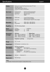
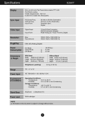
...-Condensing Stand Base Attached ( ), Detached ( O ) Power cord Wall-outlet type NOTE Information in this document is subject to 75 Hz (Automatic) Separate Sync. Vertical Freq. Input Form 30 kHz to 83 kHz (Automatic) 56 Hz to change without notice. 26 Specifications E2241T Display Sync Input Video Input 54.6 cm (21.5 inch) Flat Panel Active matrix-TFT LCD Anti-Glare coating Visible diagonal size : 54.6 cm 0.248 mm x 0.248 mm (Pixel pitch) Horizontal Freq...
...-Condensing Stand Base Attached ( ), Detached ( O ) Power cord Wall-outlet type NOTE Information in this document is subject to 75 Hz (Automatic) Separate Sync. Vertical Freq. Input Form 30 kHz to 83 kHz (Automatic) 56 Hz to change without notice. 26 Specifications E2241T Display Sync Input Video Input 54.6 cm (21.5 inch) Flat Panel Active matrix-TFT LCD Anti-Glare coating Visible diagonal size : 54.6 cm 0.248 mm x 0.248 mm (Pixel pitch) Horizontal Freq...
Owner's Manual
Page 28
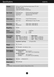
...-Condensing Stand Base Attached ( ), Detached ( O ) Power cord Wall-outlet type NOTE Information in this document is subject to 75 Hz (Automatic) Separate Sync. Input Form 30 kHz to 83 kHz (Automatic) 56 Hz to change without notice. 27 Vertical Freq. Specifications E2241S Display Sync Input 54.6 cm (21.5 inch) Flat Panel Active matrix-TFT LCD Anti-Glare coating Visible diagonal size : 54.6 cm 0.248 mm x 0.248 mm (Pixel pitch) Horizontal Freq...
...-Condensing Stand Base Attached ( ), Detached ( O ) Power cord Wall-outlet type NOTE Information in this document is subject to 75 Hz (Automatic) Separate Sync. Input Form 30 kHz to 83 kHz (Automatic) 56 Hz to change without notice. 27 Vertical Freq. Specifications E2241S Display Sync Input 54.6 cm (21.5 inch) Flat Panel Active matrix-TFT LCD Anti-Glare coating Visible diagonal size : 54.6 cm 0.248 mm x 0.248 mm (Pixel pitch) Horizontal Freq...
Owner's Manual
Page 29
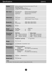
... kHz (Automatic) 56 Hz to change without notice. 28 Digital Signal Input Input Form 15 pin D-Sub Connector DVI-D Connector (Digital) RGB Analog (0.7 Vp-p/ 75 ohm), Digital Resolution Plug&Play Power Consumption Dimensions & Weight Range Power Input Environment al Conditions Max Recommend VESA 1920 x 1080 @60 Hz VESA 1920 x 1080 @60 Hz DDC 2B (Analog,Digital) On Mode Sleep Mode Off Mode : 28 W(Typ.) < 0.3 W < 0.3 W With Stand Width 54.60 cm (21.49 inch) Height 40.70 cm (16.02...
... kHz (Automatic) 56 Hz to change without notice. 28 Digital Signal Input Input Form 15 pin D-Sub Connector DVI-D Connector (Digital) RGB Analog (0.7 Vp-p/ 75 ohm), Digital Resolution Plug&Play Power Consumption Dimensions & Weight Range Power Input Environment al Conditions Max Recommend VESA 1920 x 1080 @60 Hz VESA 1920 x 1080 @60 Hz DDC 2B (Analog,Digital) On Mode Sleep Mode Off Mode : 28 W(Typ.) < 0.3 W < 0.3 W With Stand Width 54.60 cm (21.49 inch) Height 40.70 cm (16.02...

Owner's Manual
Page 30
... kHz (Automatic) 56 Hz to change without notice. 29 Digital Signal Input Input Form 15 pin D-Sub Connector DVI-D Connector (Digital) RGB Analog (0.7 Vp-p/ 75 ohm), Digital Resolution Plug&Play Power Consumption Dimensions & Weight Range Power Input Environment al Conditions Max Recommend VESA 1920 x 1080 @60 Hz VESA 1920 x 1080 @60 Hz DDC 2B (Analog,Digital) On Mode Sleep Mode Off Mode : 25 W(Typ.) < 0.3 W < 0.3 W With Stand Width 56.93 cm (22.41 inch) Height 41.91 cm (16.50...
... kHz (Automatic) 56 Hz to change without notice. 29 Digital Signal Input Input Form 15 pin D-Sub Connector DVI-D Connector (Digital) RGB Analog (0.7 Vp-p/ 75 ohm), Digital Resolution Plug&Play Power Consumption Dimensions & Weight Range Power Input Environment al Conditions Max Recommend VESA 1920 x 1080 @60 Hz VESA 1920 x 1080 @60 Hz DDC 2B (Analog,Digital) On Mode Sleep Mode Off Mode : 25 W(Typ.) < 0.3 W < 0.3 W With Stand Width 56.93 cm (22.41 inch) Height 41.91 cm (16.50...

Owner's Manual
Page 34
... Slot Connected to the installation guide for more details, which is provided when Wall mount plate is connectable with respect to screw mounting interface dimensions and mounting screw specifications Please use VESA standard wall mount pad and screws. 33 Screw : 4.0 mm x Pitch 0.7 mm x Length 10 mm * 787.4 mm and above (31.0 inch) - Please use VESA standard as below. * 784.8 mm and under (30.9 inch) - Installing the Wall mount plate .3 Install the Wall mount plate. Please refer to a locking cable...
... Slot Connected to the installation guide for more details, which is provided when Wall mount plate is connectable with respect to screw mounting interface dimensions and mounting screw specifications Please use VESA standard wall mount pad and screws. 33 Screw : 4.0 mm x Pitch 0.7 mm x Length 10 mm * 787.4 mm and above (31.0 inch) - Please use VESA standard as below. * 784.8 mm and under (30.9 inch) - Installing the Wall mount plate .3 Install the Wall mount plate. Please refer to a locking cable...


