
Owners Manual
Page 1
Record model number and serial number of the TV in the spaces provided below. Model Number : Serial Number : LG Electronics U.S.A., Inc. PLASMA TV OWNER'S MANUAL MODELS: DU-50PY10 DU-60PY10 R TruSurround XT TM Please read this manual for future reference. Retain this manual carefully and completely before operating your dealer if you require service. See the label attached on the back cover and relate this information to your TV.
Record model number and serial number of the TV in the spaces provided below. Model Number : Serial Number : LG Electronics U.S.A., Inc. PLASMA TV OWNER'S MANUAL MODELS: DU-50PY10 DU-60PY10 R TruSurround XT TM Please read this manual for future reference. Retain this manual carefully and completely before operating your dealer if you require service. See the label attached on the back cover and relate this information to your TV.
Owners Manual
Page 2
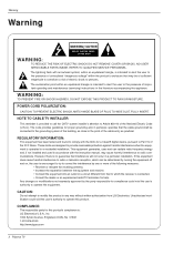
.... The lightning flash with the limits for help. NOTE TO CABLE/TV INSTALLER: This reminder is : LG Electronics U.S.A., Inc 1000 Sylvan Avenue, Englewood Cliffs, NJ 07632 1-201-816-2000 http://www.lgusa.com 2 Plasma TV WARNING: TO PREVENT FIRE OR SHOCK HAZARDS, DO NOT EXPOSE THIS ... to call the CATV system installer's attention to correct the interference by turning the equipment off and on a circuit different from LG Electronics. COMPLIANCE: The responsible party for this equipment does cause harmful interference to radio or television reception, which the receiver is encouraged...
.... The lightning flash with the limits for help. NOTE TO CABLE/TV INSTALLER: This reminder is : LG Electronics U.S.A., Inc 1000 Sylvan Avenue, Englewood Cliffs, NJ 07632 1-201-816-2000 http://www.lgusa.com 2 Plasma TV WARNING: TO PREVENT FIRE OR SHOCK HAZARDS, DO NOT EXPOSE THIS ... to call the CATV system installer's attention to correct the interference by turning the equipment off and on a circuit different from LG Electronics. COMPLIANCE: The responsible party for this equipment does cause harmful interference to radio or television reception, which the receiver is encouraged...
Owners Manual
Page 4
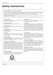
... overturn. 11. Power-Cord Polarization This product is provided or the manufacturer's instructions have been built into the grounding-type power outlet. PORTABLE CART WARNING 4 Plasma TV Attachments Do not use instructions should never be followed. 3. Follow Instructions All operating and use attachments not recommended by the product manufacturer as a bookcase or...
... overturn. 11. Power-Cord Polarization This product is provided or the manufacturer's instructions have been built into the grounding-type power outlet. PORTABLE CART WARNING 4 Plasma TV Attachments Do not use instructions should never be followed. 3. Follow Instructions All operating and use attachments not recommended by the product manufacturer as a bookcase or...
Owners Manual
Page 6
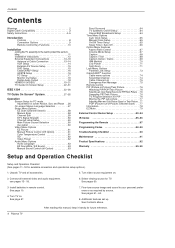
...74 Scrambled channel 74 Cable Channel List 75 Emergency Alert Message 75 Remote Control PIP (Picture-in remote control. Unpack TV and all external video and audio equipment. Contents Contents Warnings 2 Digital Cable Compatibility 3 Safety Instructions 4~5 Introduction Controls 8... Connection Options 9 Remote Control Key Functions 10 Installation Joining the TV assembly to the wall to your personal preference or as required by source. Turn TV on . 2. Turn video source equipment on . Connect all accessories. 5. Select viewing source for future reference. 6 Plasma TV
...74 Scrambled channel 74 Cable Channel List 75 Emergency Alert Message 75 Remote Control PIP (Picture-in remote control. Unpack TV and all external video and audio equipment. Contents Contents Warnings 2 Digital Cable Compatibility 3 Safety Instructions 4~5 Introduction Controls 8... Connection Options 9 Remote Control Key Functions 10 Installation Joining the TV assembly to the wall to your personal preference or as required by source. Turn TV on . 2. Turn video source equipment on . Connect all accessories. 5. Select viewing source for future reference. 6 Plasma TV
Owners Manual
Page 8
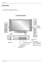
This is turned on. (If power isn't turn on or off. Front Panel Controls R TruSurround XT POWER TV GUIDE TV/VIDEO MENU VOL CH INDEX Switches LED Display on in standby mode, Illuminates green when the TV is a simplified representation of front panel. Here shown may be somewhat different from your service center.) 8 Plasma TV Introduction Controls - POWER POWER Button TV GUIDE TV/VIDEO MENU VOL CH Remote Control Sensor CHANNEL (E, D) Buttons VOLUME (F,G) Buttons MENU Button TV/VIDEO Button TV GUIDE Button Power Indicator Illuminates orange in red, contact your TV.
This is turned on. (If power isn't turn on or off. Front Panel Controls R TruSurround XT POWER TV GUIDE TV/VIDEO MENU VOL CH INDEX Switches LED Display on in standby mode, Illuminates green when the TV is a simplified representation of front panel. Here shown may be somewhat different from your service center.) 8 Plasma TV Introduction Controls - POWER POWER Button TV GUIDE TV/VIDEO MENU VOL CH Remote Control Sensor CHANNEL (E, D) Buttons VOLUME (F,G) Buttons MENU Button TV/VIDEO Button TV GUIDE Button Power Indicator Illuminates orange in red, contact your TV.
Owners Manual
Page 10
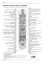
...next higher/lower PIP channel. Switches the video window locking or unlocking in the TV Guide On Screen system. PIPCH-/PIPCH+ Changes to scroll the Surf channel. ZOOM Enlarges the main picture size. 10 Plasma TV Installation Remote Control Key Functions - COMP/RGB/HDMI Selects: Component 1-2, RGB-...DTV (or RGB- LIGHT MODE POWER TV/VIDEO COMP/RGB/HDMI 1394 NUMBER buttons DASH Uses to the last channel viewed....
...next higher/lower PIP channel. Switches the video window locking or unlocking in the TV Guide On Screen system. PIPCH-/PIPCH+ Changes to scroll the Surf channel. ZOOM Enlarges the main picture size. 10 Plasma TV Installation Remote Control Key Functions - COMP/RGB/HDMI Selects: Component 1-2, RGB-...DTV (or RGB- LIGHT MODE POWER TV/VIDEO COMP/RGB/HDMI 1394 NUMBER buttons DASH Uses to the last channel viewed....
Owners Manual
Page 12
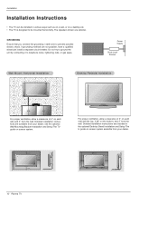
...see the optional Wall Mounting Bracket Installation and Setup The TV guide on a desktop etc. • The TV is designed to be installed in the optional Desktop Stand Installation and Setup The tv guide on screen system available from the wall. Detailed installation... and 2" from your dealer. 4 inches 4 inches 4 inches 4 inches 2 inches 4 inches 4 inches 4 inches 2.36 inches 2 inches 12 Plasma TV Detailed installation instructions are optional. GROUNDING Ensure that you connect the grounding / earth wire to telephone wires, lightening rods, or gas pipes. The speakers ...
...see the optional Wall Mounting Bracket Installation and Setup The TV guide on a desktop etc. • The TV is designed to be installed in the optional Desktop Stand Installation and Setup The tv guide on screen system available from the wall. Detailed installation... and 2" from your dealer. 4 inches 4 inches 4 inches 4 inches 2 inches 4 inches 4 inches 4 inches 2.36 inches 2 inches 12 Plasma TV Detailed installation instructions are optional. GROUNDING Ensure that you connect the grounding / earth wire to telephone wires, lightening rods, or gas pipes. The speakers ...
Owners Manual
Page 14
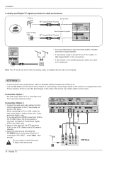
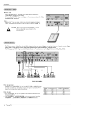
... COMPONENT2 VIDEO INPUT Cable ANTENNA CABLE AC INPUT 1 2 ANT OUT ANT IN S-VIDEO OUT OUTPUT (R) AUDIO (L) SWITCH 3 4 IN VIDEO VCR Rear 14 Plasma TV the fixed images on the sides of the screen may remain visible on the remote control. (If connected to A/V INPUT , select Video input source) Do...the audio and video cables from VCR to tighten. VCR Setup - compared to connecting a regular VCR to the same channel number. When connecting the TV to the VCR owner's manual.) 3. Insert a video tape into the VCR and press PLAY on cable and antenna Antenna Bronze Wire RF Coaxial ...
... COMPONENT2 VIDEO INPUT Cable ANTENNA CABLE AC INPUT 1 2 ANT OUT ANT IN S-VIDEO OUT OUTPUT (R) AUDIO (L) SWITCH 3 4 IN VIDEO VCR Rear 14 Plasma TV the fixed images on the sides of the screen may remain visible on the remote control. (If connected to A/V INPUT , select Video input source) Do...the audio and video cables from VCR to tighten. VCR Setup - compared to connecting a regular VCR to the same channel number. When connecting the TV to the VCR owner's manual.) 3. Insert a video tape into the VCR and press PLAY on cable and antenna Antenna Bronze Wire RF Coaxial ...
Owners Manual
Page 16
..., depending on the screen, contact with Cable service provider by phone. Use TV/VIDEO or COMP/RGB/HDMI on the digital set -top box or other digital external device, refer to the figure as this PLASMA TV. Caution: When removing the CableCARDTTMM, do receive Digital signals from Cable Service ...provider to connect Use the TV's COMPONENT (Y, PB, PR) INPUT, RGB or HDMI/DVI jack for this may cause impact...
..., depending on the screen, contact with Cable service provider by phone. Use TV/VIDEO or COMP/RGB/HDMI on the digital set -top box or other digital external device, refer to the figure as this PLASMA TV. Caution: When removing the CableCARDTTMM, do receive Digital signals from Cable Service ...provider to connect Use the TV's COMPONENT (Y, PB, PR) INPUT, RGB or HDMI/DVI jack for this may cause impact...

Owners Manual
Page 18
... damage your vision. HDMI / DVI(VIDEO) AUDIO INPUT DIGITAL AUDIO(OPTICAL) DVI COMPONENT2 VIDEO INPUT Cable ANTENNA AC INPUT 18 Plasma TV Installation Monitor Display Specifications (HDMI/DVI Mode) Resolution 640x480 800x600 Horizontal Vertical Frequency(KHz) Frequency(Hz) 31.469 37.861 59...capability which allows you to connect 1. S-VIDEO IN (R) AUDIO (L) VIDEO Digital Audio Output Send the TV's audio to page 64. cal) input on the audio equipment. 3. Set the " TV Speaker option - Refer to external audio equipment (stereo system) via the Digital Audio Output (Optical) port...
... damage your vision. HDMI / DVI(VIDEO) AUDIO INPUT DIGITAL AUDIO(OPTICAL) DVI COMPONENT2 VIDEO INPUT Cable ANTENNA AC INPUT 18 Plasma TV Installation Monitor Display Specifications (HDMI/DVI Mode) Resolution 640x480 800x600 Horizontal Vertical Frequency(KHz) Frequency(Hz) 31.469 37.861 59...capability which allows you to connect 1. S-VIDEO IN (R) AUDIO (L) VIDEO Digital Audio Output Send the TV's audio to page 64. cal) input on the audio equipment. 3. Set the " TV Speaker option - Refer to external audio equipment (stereo system) via the Digital Audio Output (Optical) port...

Owners Manual
Page 20
HDMI Reference Cable sample 20 Plasma TV HDMI Cable (not supplied with the product) HDMI to DVI Cable (not supplied with the product) Fiber Optic Digital Audio Cable (not supplied with the product) Analog Audio Cable(RCA type) (not supplied with the product) Analog Audio Cable(Stereo to RCA type) (not supplied with the product)
HDMI Reference Cable sample 20 Plasma TV HDMI Cable (not supplied with the product) HDMI to DVI Cable (not supplied with the product) Fiber Optic Digital Audio Cable (not supplied with the product) Analog Audio Cable(RCA type) (not supplied with the product) Analog Audio Cable(Stereo to RCA type) (not supplied with the product)

Owners Manual
Page 22
... On Screen System interactive program guide provides listings for satellite services. Once you set up the TV according to connect VCR and Cable Box 1. Antenna Service HDMI / DVI(VIDEO) AUDIO INPUT DIGITAL AUDIO(OPTICAL) DVI COMPONENT2 VIDEO INPUT Cable ANTENNA CABLE AC ... OUT ANT IN OUT S-VIDEO OUTPUT (R) AUDIO (L) SWITCH 3 4 IN VIDEO VCR Rear Cable ANTENNA CABLE AC INPUT VCR Front 22 Plasma TV ANT OUT ANT IN OUT OUTPUT (R) AUDIO (L) SWITCH 3 4 IN S-VIDEO VIDEO VCR Rear The TV Guide On Screen system uses Setup information to provide you are ready to set up the...
... On Screen System interactive program guide provides listings for satellite services. Once you set up the TV according to connect VCR and Cable Box 1. Antenna Service HDMI / DVI(VIDEO) AUDIO INPUT DIGITAL AUDIO(OPTICAL) DVI COMPONENT2 VIDEO INPUT Cable ANTENNA CABLE AC ... OUT ANT IN OUT S-VIDEO OUTPUT (R) AUDIO (L) SWITCH 3 4 IN VIDEO VCR Rear Cable ANTENNA CABLE AC INPUT VCR Front 22 Plasma TV ANT OUT ANT IN OUT OUTPUT (R) AUDIO (L) SWITCH 3 4 IN S-VIDEO VIDEO VCR Rear The TV Guide On Screen system uses Setup information to provide you are ready to set up the...

Owners Manual
Page 24
...1. The Welcome Screen highlights features of your Cable Box and VCR. if you to watching TV. • "Don't remind me to display Screen 2. 24 Plasma TV See Page 22~23 for the TV Guide On Screen system to work with your TV. •Use the D / E button to highlight a country. •Press ENTER to... set up TV Guide On Screen now" on the Reminder Screen. after initial TV set up TV Guide On Screen now," ...
...1. The Welcome Screen highlights features of your Cable Box and VCR. if you to watching TV. • "Don't remind me to display Screen 2. 24 Plasma TV See Page 22~23 for the TV Guide On Screen system to work with your TV. •Use the D / E button to highlight a country. •Press ENTER to... set up TV Guide On Screen now" on the Reminder Screen. after initial TV set up TV Guide On Screen now," ...

Owners Manual
Page 26
Screen 7: Cable Box Configuration Diagram •The diagram shows the correct way to install the G-LINK Cable from the back of the device to display Screen 8. 26 Plasma TV Make sure the G-LINK Cable is the cable box plugged into? •If you select Cable, you see Screen 6. •If you make any other choice, you see Screen 7 . 6. Screen 6: Cable Box Tuning Channel •Select the channel used for the cable box. •Press ENTER to display Screen 7. 7. Screen 5: Which TV input is properly installed. •Press ENTER to the cable box. Installation 5.
Screen 7: Cable Box Configuration Diagram •The diagram shows the correct way to install the G-LINK Cable from the back of the device to display Screen 8. 26 Plasma TV Make sure the G-LINK Cable is the cable box plugged into? •If you select Cable, you see Screen 6. •If you make any other choice, you see Screen 7 . 6. Screen 6: Cable Box Tuning Channel •Select the channel used for the cable box. •Press ENTER to display Screen 7. 7. Screen 5: Which TV input is properly installed. •Press ENTER to the cable box. Installation 5.

Owners Manual
Page 28
Screen 12: Do you have an antenna connected? •If you select Yes, you see Screen 13. 13. Installation 12. Note: •If you selected No in Screen 3 then you must select Yes in this screen to display Screen 15. 28 Plasma TV Screen 13: Are your basic settings correct? •If you select Yes, you see Screen 14. •If you select No, you see Screen 13. Screen 14: Congratulations •Press ENTER to receive a channel lineup and listings. •If you select No, you see Screen 1. 14.
Screen 12: Do you have an antenna connected? •If you select Yes, you see Screen 13. 13. Installation 12. Note: •If you selected No in Screen 3 then you must select Yes in this screen to display Screen 15. 28 Plasma TV Screen 13: Are your basic settings correct? •If you select Yes, you see Screen 14. •If you select No, you see Screen 13. Screen 14: Congratulations •Press ENTER to receive a channel lineup and listings. •If you select No, you see Screen 1. 14.

Owners Manual
Page 30
Screen 18: VCR Preparation Follow the on-screen instructions, and press ENTER to Channel 9? •If you select Yes, you see Screen 21. •If you select Test this code again, the same code is tested again in Screen 19. Screen 20: VCR Tuned to display Screen 19. 19. Installation 18. Screen 19: VCR Code Testing When testing is tested in Screen 19. 30 Plasma TV Note : Many VCRs require testing more than one code. •If you select No, a different code is done, Screen 20 displays automatically. 20.
Screen 18: VCR Preparation Follow the on-screen instructions, and press ENTER to Channel 9? •If you select Yes, you see Screen 21. •If you select Test this code again, the same code is tested again in Screen 19. Screen 20: VCR Tuned to display Screen 19. 19. Installation 18. Screen 19: VCR Code Testing When testing is tested in Screen 19. 30 Plasma TV Note : Many VCRs require testing more than one code. •If you select No, a different code is done, Screen 20 displays automatically. 20.

Owners Manual
Page 32
... Camcorder to show the control panel. (c) TV DVHS + MicroMV Camcorder POWER TV GUIDE TV/VIDEO MENU VOL CH When connecting the 1394 and then playing, you can used. 1. If not, it may be occurred the errors. 32 Plasma TV When connecting the DVHS or the MicroMV Camcorder..., as shown in the (a) or (b) figure, press the 1394 button to show the control panel. (a) TV DVHS (b) TV MicroMV Camcorder POWER TV GUIDE TV/VIDEO MENU VOL CH POWER TV GUIDE TV/VIDEO MENU VOL CH 2....
... Camcorder to show the control panel. (c) TV DVHS + MicroMV Camcorder POWER TV GUIDE TV/VIDEO MENU VOL CH When connecting the 1394 and then playing, you can used. 1. If not, it may be occurred the errors. 32 Plasma TV When connecting the DVHS or the MicroMV Camcorder..., as shown in the (a) or (b) figure, press the 1394 button to show the control panel. (a) TV DVHS (b) TV MicroMV Camcorder POWER TV GUIDE TV/VIDEO MENU VOL CH POWER TV GUIDE TV/VIDEO MENU VOL CH 2....
Owners Manual
Page 34
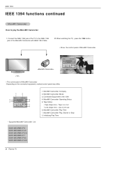
... Connect the IEEE 1394 jack of the TV to the IEEE 1394 jack of MicroMV Camcorder. MicroMV Camcorder Model 3. Use or not use 6. Tape Status • Tape shape Icon - MicroMV Camcorder Operating Status 5. Initializing Play Time 34 Plasma TV MicroMV Camcorder Play, Search or Stop 8. ...When watching the TV, press the 1394 button. • Show the control panel of the MicroMV Camcorder with IEEE 1394 Cable. 2....
... Connect the IEEE 1394 jack of the TV to the IEEE 1394 jack of MicroMV Camcorder. MicroMV Camcorder Model 3. Use or not use 6. Tape Status • Tape shape Icon - MicroMV Camcorder Operating Status 5. Initializing Play Time 34 Plasma TV MicroMV Camcorder Play, Search or Stop 8. ...When watching the TV, press the 1394 button. • Show the control panel of the MicroMV Camcorder with IEEE 1394 Cable. 2....

Owners Manual
Page 36
IEEE 1394 IEEE 1394 functions continued How to connect the 1394 • When connecting these 3 methods, the 1394 will not work properly. (a) LOOP Connection (b) Daisy Chain POWER TV GUIDE TV/VIDEO MENU VOL CH POWER TV GUIDE TV/VIDEO MENU VOL CH (c) MicroMV Camcorder Daisy Chain POWER TV GUIDE TV/VIDEO MENU VOL CH or 36 Plasma TV
IEEE 1394 IEEE 1394 functions continued How to connect the 1394 • When connecting these 3 methods, the 1394 will not work properly. (a) LOOP Connection (b) Daisy Chain POWER TV GUIDE TV/VIDEO MENU VOL CH POWER TV GUIDE TV/VIDEO MENU VOL CH (c) MicroMV Camcorder Daisy Chain POWER TV GUIDE TV/VIDEO MENU VOL CH or 36 Plasma TV

Owners Manual
Page 38
...- location where show is displayed •Service Bar - displays show title •Highlight - displays TV video while the Guide is set to Record or set as shown in the TV Guide On Screen system share many of the same compo- indented to the 4 main Guide Services ... Service Label - indicates an active tile •Info Box - or product-specific information appears (and also where Panel Menu appears) 38 Plasma TV provides access to indicate current Service displayed •Tile - identifies network •Record/Remind Icons - The screens displayed in the following figure...
...- location where show is displayed •Service Bar - displays show title •Highlight - displays TV video while the Guide is set to Record or set as shown in the TV Guide On Screen system share many of the same compo- indented to the 4 main Guide Services ... Service Label - indicates an active tile •Info Box - or product-specific information appears (and also where Panel Menu appears) 38 Plasma TV provides access to indicate current Service displayed •Tile - identifies network •Record/Remind Icons - The screens displayed in the following figure...


