
Owner's Manual (English)
Page 1
... in Korea S. Record model number and serial number of the set of power-saving guidelines issued by the U.S. A.,Inc. Retain it for energy efficiency. LCD TV MODELS: 32LC2D 32LC2DU 37LC2D 42LC2D PLASMA TV MODELS: 42PC3D 42PC3DC 42PC3DV 50PC3D 60PC1D 60PC1DC OWNER'S MANUAL Internet Home Page : http://www.lge.com http://www...
... in Korea S. Record model number and serial number of the set of power-saving guidelines issued by the U.S. A.,Inc. Retain it for energy efficiency. LCD TV MODELS: 32LC2D 32LC2DU 37LC2D 42LC2D PLASMA TV MODELS: 42PC3D 42PC3DC 42PC3DV 50PC3D 60PC1D 60PC1DC OWNER'S MANUAL Internet Home Page : http://www.lge.com http://www...

Owner's Manual (English)
Page 2
... could void the user's authority to Part 15 of the following measures: - NOTE TO CABLE/TV INSTALLER: This reminder is connected. - Consult the dealer or an experienced radio/TV technician for a Class B digital device, pursuant to operate the equipment. If this product in ...to call the CATV system installer's attention to correct the interference by turning the equipment off and on a circuit different from LG Electronics Corporation. REFER TO QUALIFIED SERVICE PERSONNEL. COMPLIANCE: The responsible party for compliance could void the user's authority to operate this...
... could void the user's authority to Part 15 of the following measures: - NOTE TO CABLE/TV INSTALLER: This reminder is connected. - Consult the dealer or an experienced radio/TV technician for a Class B digital device, pursuant to operate the equipment. If this product in ...to call the CATV system installer's attention to correct the interference by turning the equipment off and on a circuit different from LG Electronics Corporation. REFER TO QUALIFIED SERVICE PERSONNEL. COMPLIANCE: The responsible party for compliance could void the user's authority to operate this...

Owner's Manual (English)
Page 3
Keep these instructions. Do not use the attachments / accessories specified by the manufacturer. 3 A grounding type plug has two blades and a third grounding prong. The wide blade or the third prong is provided for your outlet, consult an electrician for replacement of the obsolete outlet. 10. Protect the power cord from being walked on the apparatus. Install in accordance with a dry cloth. 8. Do not defeat the safety purpose of the polarized or grounding type plug. Only use this apparatus to dripping or splashing and no objects filled with one wider than the other ...
Keep these instructions. Do not use the attachments / accessories specified by the manufacturer. 3 A grounding type plug has two blades and a third grounding prong. The wide blade or the third prong is provided for your outlet, consult an electrician for replacement of the obsolete outlet. 10. Protect the power cord from being walked on the apparatus. Install in accordance with a dry cloth. 8. Do not defeat the safety purpose of the polarized or grounding type plug. Only use this apparatus to dripping or splashing and no objects filled with one wider than the other ...

Owner's Manual (English)
Page 4
... must remain readily operable. Any of these conditions could result in this product with an exact replacement part by the manufacturer, or sold with TV. - FOR LCD TV Note - On Disposal a. When a cart is damaged, liquid has been spilled or objects have fallen into the apparatus, the apparatus has ...been exposed to the touch, there may produce some temporary distortion effects on . If the TV feels cold to rain or moisture, does not operate normally, or has been dropped. 13. Doing so may be a small "flicker" when when...
... must remain readily operable. Any of these conditions could result in this product with an exact replacement part by the manufacturer, or sold with TV. - FOR LCD TV Note - On Disposal a. When a cart is damaged, liquid has been spilled or objects have fallen into the apparatus, the apparatus has ...been exposed to the touch, there may produce some temporary distortion effects on . If the TV feels cold to rain or moisture, does not operate normally, or has been dropped. 13. Doing so may be a small "flicker" when when...

Owner's Manual (English)
Page 5
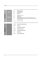
... Audio Menu Options 14 15 16~17 18 19~20 20 21~22 23~24 25 25 26~28 Attaching the TV to a wall Desktop Pedestal Installation Basic Connection Antenna or Cable Connection VCR Setup External AV Source Setup DVD Setup HDSTB ...29 29 29 30 31 31 32 33 33 34 35 35~36 37 38 39 40 41 41~42 43 43 Turning on the TV Volume Adjustment Channel Selection On Screen Menus Language Selection On Screen Menus Selection and Adjustment EZ Scan (Channel ... Level Video Reset Audio Language Auto Sound Control(EZ Sound) Manual Sound Control (EZ Sound-User option) Balance TV Speakers On/Off Setup Operation Contents 5
... Audio Menu Options 14 15 16~17 18 19~20 20 21~22 23~24 25 25 26~28 Attaching the TV to a wall Desktop Pedestal Installation Basic Connection Antenna or Cable Connection VCR Setup External AV Source Setup DVD Setup HDSTB ...29 29 29 30 31 31 32 33 33 34 35 35~36 37 38 39 40 41 41~42 43 43 Turning on the TV Volume Adjustment Channel Selection On Screen Menus Language Selection On Screen Menus Selection and Adjustment EZ Scan (Channel ... Level Video Reset Audio Language Auto Sound Control(EZ Sound) Manual Sound Control (EZ Sound-User option) Balance TV Speakers On/Off Setup Operation Contents 5
Owner's Manual (English)
Page 6
Contents Operation Time Menu Options Option Menu Features Lock Menu Options 44 44 45 45 46 47 48 49 49 50 51~52 Manual Clock Setup Auto Clock Setup On/Off Timer Setup Sleep Timer Auto Off Aspect Ratio Control Caption/Text Caption Option Low Power (42PC3D/3DC/3DV, 50PC3D, 60PC1D/1DC Only) ISM (Image Sticking Minimization) Method (42PC3D/3DC/3DV, 50PC3D, 60PC1D/1DC Only) Parental Lock Setup 53~58 59~60 61 62~63 64~65 65 66~67 External Control Device Setup IR Codes Programming the Remote Programming Codes Troubleshooting Checklist Maintenance Product Specifications Reference 6
Contents Operation Time Menu Options Option Menu Features Lock Menu Options 44 44 45 45 46 47 48 49 49 50 51~52 Manual Clock Setup Auto Clock Setup On/Off Timer Setup Sleep Timer Auto Off Aspect Ratio Control Caption/Text Caption Option Low Power (42PC3D/3DC/3DV, 50PC3D, 60PC1D/1DC Only) ISM (Image Sticking Minimization) Method (42PC3D/3DC/3DV, 50PC3D, 60PC1D/1DC Only) Parental Lock Setup 53~58 59~60 61 62~63 64~65 65 66~67 External Control Device Setup IR Codes Programming the Remote Programming Codes Troubleshooting Checklist Maintenance Product Specifications Reference 6

Owner's Manual (English)
Page 7
... that the following accessories are included with the cloth. Please be cautious of the exterior. Stand Installation for the product. For 60PC1D/1DC 2-TV brackets 2-Wall brackets 4- CABLMEODDEVD INPUT MENU VCR STB GUIDE ENTER DAY+ RATIO TIMER EXIT VOL MUTE CC PAGE INFO 1 4 7 2... FAV PAGE CH 5 EZ ADJUST PIC EZ APM SOUND 0 SAP 8 9 FLASHBK 6 3 FREEZE TV INPUT 1.5V DAY - Bolts 4-RING SPACER Polishing Cloth Polish the TV with your TV. User must use shielded signal interface cables(D-sub 15 pin cable) with the cleansing cloths for the product exterior...
... that the following accessories are included with the cloth. Please be cautious of the exterior. Stand Installation for the product. For 60PC1D/1DC 2-TV brackets 2-Wall brackets 4- CABLMEODDEVD INPUT MENU VCR STB GUIDE ENTER DAY+ RATIO TIMER EXIT VOL MUTE CC PAGE INFO 1 4 7 2... FAV PAGE CH 5 EZ ADJUST PIC EZ APM SOUND 0 SAP 8 9 FLASHBK 6 3 FREEZE TV INPUT 1.5V DAY - Bolts 4-RING SPACER Polishing Cloth Polish the TV with your TV. User must use shielded signal interface cables(D-sub 15 pin cable) with the cleansing cloths for the product exterior...
Owner's Manual (English)
Page 8
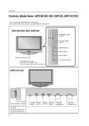
... Button VOLUME (F,G)Buttons CHANNEL (E,D)Buttons Introduction Controls (Model Name: 42PC3D/3DC/3DV, 50PC3D, 60PC1D/1DC) - This picture shown below may be somewhat different from your TV. 42PC3D/3DC/3DV, 50PC3D Remote Control Sensor Power/Standby Indicator • illuminates red in standby mode.
... Button VOLUME (F,G)Buttons CHANNEL (E,D)Buttons Introduction Controls (Model Name: 42PC3D/3DC/3DV, 50PC3D, 60PC1D/1DC) - This picture shown below may be somewhat different from your TV. 42PC3D/3DC/3DV, 50PC3D Remote Control Sensor Power/Standby Indicator • illuminates red in standby mode.

Owner's Manual (English)
Page 9
... RS-232C port on DC power. Note: In standby mode, these jacks. Or DVI (VIDEO)signal to the 1(DVI) port with a DVI to operate the TV on a PC. 10 SERVICE 11 Power Cord Socket For operation with AC power. Caution: Never attempt to HDMI cable. S-VIDEO VIDEO ( ) AUDIO 9 S-VIDEO VIDEO (... video/audio device to these jacks. 7 RGB IN (PC) Connect the monitor output from a PC to the appropriate input port. 2 AV OUT Connect a second TV or monitor. 3 AV (Audio/Video) IN 1 Connect audio/video output from an S-VIDEO device. 4 ANTENNA/CABLE IN Connect over-the air signals to this jack...
... RS-232C port on DC power. Note: In standby mode, these jacks. Or DVI (VIDEO)signal to the 1(DVI) port with a DVI to operate the TV on a PC. 10 SERVICE 11 Power Cord Socket For operation with AC power. Caution: Never attempt to HDMI cable. S-VIDEO VIDEO ( ) AUDIO 9 S-VIDEO VIDEO (... video/audio device to these jacks. 7 RGB IN (PC) Connect the monitor output from a PC to the appropriate input port. 2 AV OUT Connect a second TV or monitor. 3 AV (Audio/Video) IN 1 Connect audio/video output from an S-VIDEO device. 4 ANTENNA/CABLE IN Connect over-the air signals to this jack...

Owner's Manual (English)
Page 10
... Remote Control Sensor Power/Standby Indicator • illuminates red in standby mode. • illuminates green when the set is a simplified representation of front panel. - The TV can be somewhat different from your...
... Remote Control Sensor Power/Standby Indicator • illuminates red in standby mode. • illuminates green when the set is a simplified representation of front panel. - The TV can be somewhat different from your...

Owner's Manual (English)
Page 11
...toS-VIDEO VIDEO AV IN 1 7 RGB IN (PC) ( ) AUDIO Connect the monitor output from a PC to the appropriate input port. 2 AV OUT Connect a second TV or monitor. 3 AV (Audio/Video) IN 1 Connect audio/video output from a PC to the appropriate input port. 9 RS-232C IN (CONTROL & SERVICE) PORT Connect...to the RS-232C port on DC power. 6 HDMI IN Connect a HDMI signal to these ports do not work. 8 Remote Control Port Connect your TV. This picture shown below may be somewhat different from a video device. COMPONENT IN VIDEO AUDIO AV OUT AV IN 1 COMPONENT IN VIDEO AUDIO Introduction ...
...toS-VIDEO VIDEO AV IN 1 7 RGB IN (PC) ( ) AUDIO Connect the monitor output from a PC to the appropriate input port. 2 AV OUT Connect a second TV or monitor. 3 AV (Audio/Video) IN 1 Connect audio/video output from a PC to the appropriate input port. 9 RS-232C IN (CONTROL & SERVICE) PORT Connect...to the RS-232C port on DC power. 6 HDMI IN Connect a HDMI signal to these ports do not work. 8 Remote Control Port Connect your TV. This picture shown below may be somewhat different from a video device. COMPONENT IN VIDEO AUDIO AV OUT AV IN 1 COMPONENT IN VIDEO AUDIO Introduction ...
Owner's Manual (English)
Page 12
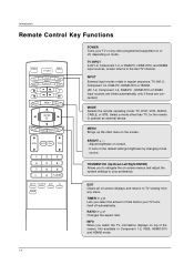
...mode source. BRIGHT + / - THUMBSTICK (Up/Down/Left/Right/ENTER) Allows you select the amount of the screen. Adjust brightness on mode. TV INPUT In AV1-2, Component 1-2, or RGB-PC, HDMI1/DVI, and HDMI2 input sources, screen returns to operate an external device. Introduction Remote ...Control Key Functions TV INPUT POWER TV AUDIO DVD MODE CABLE INPUT VCR STB BRIGHT - INPUT External input modes rotate in Component 1-2, RGB, HDMI1/DVI and HDMI2 mode....
...mode source. BRIGHT + / - THUMBSTICK (Up/Down/Left/Right/ENTER) Allows you select the amount of the screen. Adjust brightness on mode. TV INPUT In AV1-2, Component 1-2, or RGB-PC, HDMI1/DVI, and HDMI2 input sources, screen returns to operate an external device. Introduction Remote ...Control Key Functions TV INPUT POWER TV AUDIO DVD MODE CABLE INPUT VCR STB BRIGHT - INPUT External input modes rotate in Component 1-2, RGB, HDMI1/DVI and HDMI2 mode....

Owner's Manual (English)
Page 13
Introduction TV INPUT POWER TV AUDIO DVD MODE CABLE INPUT VCR STB BRIGHT - CHANNEL UP/DOWN Selects available channels found with EZ scan and Manual scan. Change the audio language ...
Introduction TV INPUT POWER TV AUDIO DVD MODE CABLE INPUT VCR STB BRIGHT - CHANNEL UP/DOWN Selects available channels found with EZ scan and Manual scan. Change the audio language ...

Owner's Manual (English)
Page 14
.... Ensure the eye-bolts or brackets are tightened securely. I Install two 1.5V AA batteries. MENU BRIGHT + ENTER EXIT TIMER RATIO INFO TV INPUT POWER TV AUDIO DVD MODE CABLE INPUT VCR STB BRIGHT - I Dispose of used batteries with the bolts (not provided as parts of the product,...with -). Introduction Installing Batteries Remote control effective range 32/37/42LC2D, 32LC2DU 42PC3D/3DC/3DV, 50PC3D 60PC1D/1DC I Use a remote control up the TV close to a wall so it cannot be pulled in a recycle bin to preserve environment. MENU BRIGHT + ENTER EXIT TIMER RATIO INFO I Open the...
.... Ensure the eye-bolts or brackets are tightened securely. I Install two 1.5V AA batteries. MENU BRIGHT + ENTER EXIT TIMER RATIO INFO TV INPUT POWER TV AUDIO DVD MODE CABLE INPUT VCR STB BRIGHT - I Dispose of used batteries with the bolts (not provided as parts of the product,...with -). Introduction Installing Batteries Remote control effective range 32/37/42LC2D, 32LC2DU 42PC3D/3DC/3DV, 50PC3D 60PC1D/1DC I Use a remote control up the TV close to a wall so it cannot be pulled in a recycle bin to preserve environment. MENU BRIGHT + ENTER EXIT TIMER RATIO INFO I Open the...

Owner's Manual (English)
Page 15
... telephone wires, lightening rods, or gas pipes. 15 Installation Installation DESKTOP PEDESTAL INSTALLATION For proper ventilation, allow a clearance of 4inches on each side from your TV. If grounding methods are not possible, have a qualified electrician install a separate circuit breaker. I This picture shown below may be somewhat different from the wall. 42PC3D...
... telephone wires, lightening rods, or gas pipes. 15 Installation Installation DESKTOP PEDESTAL INSTALLATION For proper ventilation, allow a clearance of 4inches on each side from your TV. If grounding methods are not possible, have a qualified electrician install a separate circuit breaker. I This picture shown below may be somewhat different from the wall. 42PC3D...
Owner's Manual (English)
Page 16
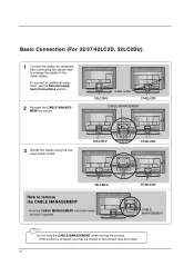
Hold the CABLE MANAGEMENT with both hands and pull it upward. 37/42LC2D CABLE MANAGEMENT Do not hold the CABLE MANAGEMENT when moving the product. - To connect an additional equipment, see the External equipment Connections section. 2 Reinstall the CABLE MANAGEMENT as necessary. After connecting the cables neatly, arrange the cables to remove the CABLE MANAGEMENT - If the product is dropped, you may be injured or the product may be broken. 16 Basic Connection (For 32/37/42LC2D, 32LC2DU) 1 Connect the cables as shown. 32LC2D/U Cable holder 37/42LC2D CABLE MANAGEMENT 3 Bundle ...
Hold the CABLE MANAGEMENT with both hands and pull it upward. 37/42LC2D CABLE MANAGEMENT Do not hold the CABLE MANAGEMENT when moving the product. - To connect an additional equipment, see the External equipment Connections section. 2 Reinstall the CABLE MANAGEMENT as necessary. After connecting the cables neatly, arrange the cables to remove the CABLE MANAGEMENT - If the product is dropped, you may be injured or the product may be broken. 16 Basic Connection (For 32/37/42LC2D, 32LC2DU) 1 Connect the cables as shown. 32LC2D/U Cable holder 37/42LC2D CABLE MANAGEMENT 3 Bundle ...
Owner's Manual (English)
Page 17
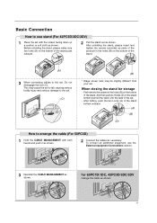
When closing the stand for storage - After folding, push the two Locks (A) of the stand bottom outward. (A) (B) (D) How to arrange the cable (For 50PC3D) 1 Hold the CABLE MANAGEMENT with the screen facing down on the bottom of the stand push outward. 2 Pull the stand out as shown. To connect an additional equipment, see the External equipment Connections section. 3 Reinstall the CABLE MANAGEMENT as shown. 17 After unfolding the stand, please insert and tighten the screws (provided as parts of the product) in the holes (B) on a cushion or soft cloth as shown. And then ...
When closing the stand for storage - After folding, push the two Locks (A) of the stand bottom outward. (A) (B) (D) How to arrange the cable (For 50PC3D) 1 Hold the CABLE MANAGEMENT with the screen facing down on the bottom of the stand push outward. 2 Pull the stand out as shown. To connect an additional equipment, see the External equipment Connections section. 3 Reinstall the CABLE MANAGEMENT as shown. 17 After unfolding the stand, please insert and tighten the screws (provided as parts of the product) in the holes (B) on a cushion or soft cloth as shown. And then ...

Owner's Manual (English)
Page 18
... antenna direction if needed. Outdoor Antenna Single-family Dwellings /Houses (Connect to wall jack for outdoor antenna) Analog and Digital TV signals provided on cable Cable TV Wall Jack RF Coaxial Wire (75 ohm) Bronze Wire Be careful not to tighten. Analog and DTV signals provided on antenna... Equipment Connections NOTE: All cables shown are not included with the TV Antenna Or Cable Connection Analog and Digital TV signals provided on two separate antennas Antenna Bronze Wire RF Coaxial Wire (75 ohm) Cable TV Wall Jack Turn clockwise to bend the bronze wire when connecting the...
... antenna direction if needed. Outdoor Antenna Single-family Dwellings /Houses (Connect to wall jack for outdoor antenna) Analog and Digital TV signals provided on cable Cable TV Wall Jack RF Coaxial Wire (75 ohm) Bronze Wire Be careful not to tighten. Analog and DTV signals provided on antenna... Equipment Connections NOTE: All cables shown are not included with the TV Antenna Or Cable Connection Analog and Digital TV signals provided on two separate antennas Antenna Bronze Wire RF Coaxial Wire (75 ohm) Cable TV Wall Jack Turn clockwise to bend the bronze wire when connecting the...
Owner's Manual (English)
Page 19
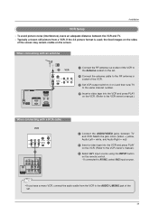
... set . 2 Connect the antenna cable to the RF antenna in socket of the VCR. 3 Set VCR output switch to 3 or 4 and then tune TV to the same channel number. 4 Insert a video tape into the VCR and press PLAY on the VCR. (Refer to AV IN2, select AV2 input source...OPTICAL DIGITAL AUDIO ( ) VIDEOS-VIDEO VIDEOAUDIO AUDIO OUT 1 Connect the AUDIO/VIDEO jacks between the VCR and TV. - If the 4:3 picture format is used; To avoid picture noise (interference), leave an adequate distance between TV and VCR. Typically a frozen still picture from the VCR to the VCR owner's manual.) 3 Select AV1 ...
... set . 2 Connect the antenna cable to the RF antenna in socket of the VCR. 3 Set VCR output switch to 3 or 4 and then tune TV to the same channel number. 4 Insert a video tape into the VCR and press PLAY on the VCR. (Refer to AV IN2, select AV2 input source...OPTICAL DIGITAL AUDIO ( ) VIDEOS-VIDEO VIDEOAUDIO AUDIO OUT 1 Connect the AUDIO/VIDEO jacks between the VCR and TV. - If the 4:3 picture format is used; To avoid picture noise (interference), leave an adequate distance between TV and VCR. Typically a frozen still picture from the VCR to the VCR owner's manual.) 3 Select AV1 ...

Owner's Manual (English)
Page 20
... the S-Video will work. compared to normal composite (RCA cable) input. 2 Connect the audio outputs of the VCR to external equipment operating guide. • This TV finds the connected input sources automatically for AV1, AV2, Component 1-2, RGB, HDMI1/DVI and HDMI2 sources are connected. 20 If connected to AV IN1 input..., select AV1 input source. 3 Operate the corresponding external equipment. External AV Source Setup Camcorder Video Game Set 1 L AUDIO R VIDEO 1 Connect the AUDIO/VIDEO jacks between TV and external equipment. If connected to AV IN2, select AV2 input source.
... the S-Video will work. compared to normal composite (RCA cable) input. 2 Connect the audio outputs of the VCR to external equipment operating guide. • This TV finds the connected input sources automatically for AV1, AV2, Component 1-2, RGB, HDMI1/DVI and HDMI2 sources are connected. 20 If connected to AV IN1 input..., select AV1 input source. 3 Operate the corresponding external equipment. External AV Source Setup Camcorder Video Game Set 1 L AUDIO R VIDEO 1 Connect the AUDIO/VIDEO jacks between TV and external equipment. If connected to AV IN2, select AV2 input source.