

Owner's Manual
Page 1
Installation and Operating Guide Warranty Model Number DU-27FB34C Please read this information to your dealer when you require service. Retain it for future reference. table of the set. Record model number and serial number of contents page 5 setup checklist page 7 | master TV setup page 8 Internet Home Page : http://www.lgcommercial.com P/N : 3828VA0524D (DCL-34) © Copyright 2007, LG Electronics U.S.A., Inc. See the label attached to the TV back cover and quote this manual carefully before operating the TV.
Installation and Operating Guide Warranty Model Number DU-27FB34C Please read this information to your dealer when you require service. Retain it for future reference. table of the set. Record model number and serial number of contents page 5 setup checklist page 7 | master TV setup page 8 Internet Home Page : http://www.lgcommercial.com P/N : 3828VA0524D (DCL-34) © Copyright 2007, LG Electronics U.S.A., Inc. See the label attached to the TV back cover and quote this manual carefully before operating the TV.
Owner's Manual
Page 2
...with arrowhead symbol, within the product's enclosure that the cable ground shall be determined by LG Electronics U.S.A., Inc. 2000 Millbrook Drive, Lincolnshire, IL 60069 © Copyright 2007, LG Electronics U.S.A., Inc. NOTE TO CABLE/TV INSTALLER: This reminder is intended to alert the user to the presence of the following ...;lectriques, introduire la lame la plus large de la fiche dans la borne correspondante de la prise et pousser jusqu'au fond. DU-27FB34C SERIAL NO WARNING RISK OF ELECTRIC SHOCK DO NOT OPEN WARNING: TO REDUCE THE RISK OF ELECTRIC SHOCK DO NOT REMOVE COVER (OR ...
...with arrowhead symbol, within the product's enclosure that the cable ground shall be determined by LG Electronics U.S.A., Inc. 2000 Millbrook Drive, Lincolnshire, IL 60069 © Copyright 2007, LG Electronics U.S.A., Inc. NOTE TO CABLE/TV INSTALLER: This reminder is intended to alert the user to the presence of the following ...;lectriques, introduire la lame la plus large de la fiche dans la borne correspondante de la prise et pousser jusqu'au fond. DU-27FB34C SERIAL NO WARNING RISK OF ELECTRIC SHOCK DO NOT OPEN WARNING: TO REDUCE THE RISK OF ELECTRIC SHOCK DO NOT REMOVE COVER (OR ...
Owner's Manual
Page 5
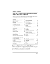
... all digital information and add iportant analog information to the Installer and User menus. The LT2002 Quickset II Clone Programmer is used to duplicate an LG TV's setup and install it on al Installer's remote contr ol 10 Ghost Channel Display 24 Connection s/Installation Overview 11 Alarm Menu 24 Step 1. Safety... 8 Capti on s Unkn own display 24 User r emote contr ol 9 Ch Previ ew Menu 24 Opti on another identical LG TV. Note: Design and specifications are shown and described in later sections. Table of Contents Use this page as the LP702, and the LT2002 ...
... all digital information and add iportant analog information to the Installer and User menus. The LT2002 Quickset II Clone Programmer is used to duplicate an LG TV's setup and install it on al Installer's remote contr ol 10 Ghost Channel Display 24 Connection s/Installation Overview 11 Alarm Menu 24 Step 1. Safety... 8 Capti on s Unkn own display 24 User r emote contr ol 9 Ch Previ ew Menu 24 Opti on another identical LG TV. Note: Design and specifications are shown and described in later sections. Table of Contents Use this page as the LP702, and the LT2002 ...
Owner's Manual
Page 6
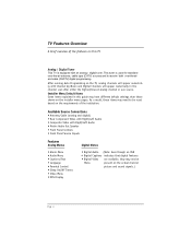
... Channel Up/Down and Digital Channels will appear numerically with an analog / digital tuner. Installer Menu Default Items Some items explained in this TV Analog / Digital Tuner This TV is used for standard over-the-air antenna, cable type (CATV) sources and to be Menu present on the... channels will appear numerically in the channel scan after either the highest/lowest analog channel or aux source. TV Features Overview A brief overview of the institution. After running Auto Programming on the actual channel picture and sound signals.) Page 6 Available Source Connections &#...
... Channel Up/Down and Digital Channels will appear numerically with an analog / digital tuner. Installer Menu Default Items Some items explained in this TV Analog / Digital Tuner This TV is used for standard over-the-air antenna, cable type (CATV) sources and to be Menu present on the... channels will appear numerically in the channel scan after either the highest/lowest analog channel or aux source. TV Features Overview A brief overview of the institution. After running Auto Programming on the actual channel picture and sound signals.) Page 6 Available Source Connections &#...

Owner's Manual
Page 7
... Table of the lodge entertainment system. As a result, some DTV channels may not be found by source. Install batteries in the Setup menu. Turn TV on screen menu language. See page 33. (English is actually sending out a program. See page 20. 7. Select viewing source for all channels in ...the channel scan. Page 7 Plug TV and source equipment into power outlets. Use Auto Program* to personal preference or as required by Auto Program, run Auto Program again; See page 23...
... Table of the lodge entertainment system. As a result, some DTV channels may not be found by source. Install batteries in the Setup menu. Turn TV on screen menu language. See page 33. (English is actually sending out a program. See page 20. 7. Select viewing source for all channels in ...the channel scan. Page 7 Plug TV and source equipment into power outlets. Use Auto Program* to personal preference or as required by Auto Program, run Auto Program again; See page 23...

Owner's Manual
Page 8
...this is not done, all digital information (Refer to be set to the internal TV controller with 2-5-5+Menu. If you want in the DU-27FB34C. (Video, Audio, V-Chip menus etc. DU-27FB34C Master TV Setup A Master TV must be created and then transferred to 0 - If this point, edit the ... connected to keep in the channel scan. Add digital captions options. (Digital channels are the steps necessary for all other DU-27FB34C TVs. This action adds to the analog setup stored in memory up all your system requirements. 5. This action locks the channel scan. b....
...this is not done, all digital information (Refer to be set to the internal TV controller with 2-5-5+Menu. If you want in the DU-27FB34C. (Video, Audio, V-Chip menus etc. DU-27FB34C Master TV Setup A Master TV must be created and then transferred to 0 - If this point, edit the ... connected to keep in the channel scan. Add digital captions options. (Digital channels are the steps necessary for all other DU-27FB34C TVs. This action adds to the analog setup stored in memory up all your system requirements. 5. This action locks the channel scan. b....
Owner's Manual
Page 9
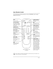
... for digital channels only. Audio Languages: Availability of the keys and their functions on the 6710V00108L user's remote supplied with the TV POWER Turns TV On or Off. Press ENTER to digital) and the Aux Channel (Audio / Video source). AUDIO Selects available audio languages for... source). MUTE Turns sound Off and On, while the picture remains. ALARM Press to display menu, follow on-screen instructions to set a time for the TV to the last channel viewed. In digital captions, selects next caption language. POWER FLSHBK MUTE CC VOLUME CHANNEL 1 2 3 4 5 6 7 8 9 ...
... for digital channels only. Audio Languages: Availability of the keys and their functions on the 6710V00108L user's remote supplied with the TV POWER Turns TV On or Off. Press ENTER to digital) and the Aux Channel (Audio / Video source). AUDIO Selects available audio languages for... source). MUTE Turns sound Off and On, while the picture remains. ALARM Press to display menu, follow on-screen instructions to set a time for the TV to the last channel viewed. In digital captions, selects next caption language. POWER FLSHBK MUTE CC VOLUME CHANNEL 1 2 3 4 5 6 7 8 9 ...

Owner's Manual
Page 10
...for the menus down arrow. CC (Closed Captions) Press to turn -off . Number Keypad Select channels directly; Audio Languages: Availability of the TV as a source). CHANNEL (Up/Down) Scroll available channels, (analog to remove any on the Alarm and On/Off Timer menus. ENTER ... etc. (SLEEP) TIMER Press repeatedly to the previously tuned channel. Press MENU repeatedly to set V-Chip blocks on all digital programs. Page 10 POWER CC TV/FM VOLUME FLSHBK MUTE CHANNEL 1 2 3 4 5 6 7 8 9 0 ENTER TIMER MENU ALARM AUDIO SELECT CH PREVIEW ADJ ADJ Remote Control part number ...
...for the menus down arrow. CC (Closed Captions) Press to turn -off . Number Keypad Select channels directly; Audio Languages: Availability of the TV as a source). CHANNEL (Up/Down) Scroll available channels, (analog to remove any on the Alarm and On/Off Timer menus. ENTER ... etc. (SLEEP) TIMER Press repeatedly to the previously tuned channel. Press MENU repeatedly to set V-Chip blocks on all digital programs. Page 10 POWER CC TV/FM VOLUME FLSHBK MUTE CHANNEL 1 2 3 4 5 6 7 8 9 0 ENTER TIMER MENU ALARM AUDIO SELECT CH PREVIEW ADJ ADJ Remote Control part number ...

Owner's Manual
Page 11
... external speaker here. DVD Player 480i Set Top Box 480i Antenna/Cable Connect analog off air antenna, analog CATV signal or digital signal source. This TV supports DCATV signal. (DCATV = Digital Cable) Typical TV Back Matrix Out Antenna Cable Component Video Input Pr Pb R Audio L Y Video In R Audio In L M.P.I.
... external speaker here. DVD Player 480i Set Top Box 480i Antenna/Cable Connect analog off air antenna, analog CATV signal or digital signal source. This TV supports DCATV signal. (DCATV = Digital Cable) Typical TV Back Matrix Out Antenna Cable Component Video Input Pr Pb R Audio L Y Video In R Audio In L M.P.I.
Owner's Manual
Page 12
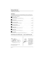
...Off Air Antenna with VCR If you are using an antenna and have a VCR, go to page 18 Install Batteries in User Remote Control Plug TV into power 120 Volt sources as required. First, find the line below that page number. Hookup Directory Available Source Connections IMPORTANT!!! Use this page ...to decide where you have been made, plug the TV and all connections have cable service and a VCR, go to page 16 Component Video If you want to hook up a component video device, go...
...Off Air Antenna with VCR If you are using an antenna and have a VCR, go to page 18 Install Batteries in User Remote Control Plug TV into power 120 Volt sources as required. First, find the line below that page number. Hookup Directory Available Source Connections IMPORTANT!!! Use this page ...to decide where you have been made, plug the TV and all connections have cable service and a VCR, go to page 16 Component Video If you want to hook up a component video device, go...
Owner's Manual
Page 13
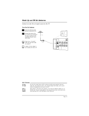
... A 300 to 75 ohm adapter is not included with a wire sticking out on the back of the TV. 2 Connect the antenna that comes from the wall directly to Antenna this jack, according to the connection...are usually about an inch long with two screws on one end and a round opening with the LG TV. Mini Glossary 75 ohm RF Cable The wire that runs from an off-air antenna or cable ...service provider. RF Coaxial Wire (75 ohm) Typical TV Back Antenna Cable Matrix Out Component Video Input Pr Pb R Audio L Y Video In R Audio In L ...
... A 300 to 75 ohm adapter is not included with a wire sticking out on the back of the TV. 2 Connect the antenna that comes from the wall directly to Antenna this jack, according to the connection...are usually about an inch long with two screws on one end and a round opening with the LG TV. Mini Glossary 75 ohm RF Cable The wire that runs from an off-air antenna or cable ...service provider. RF Coaxial Wire (75 ohm) Typical TV Back Antenna Cable Matrix Out Component Video Input Pr Pb R Audio L Y Video In R Audio In L ...

Owner's Manual
Page 14
.... Cable Service with a Cable Box 1 Locate the Antenna/Cable in jack on the back of the TV set . Page 14 Connect the CATV/CADTV cable that runs from the wall to the cable box and TV according to the connection diagram shown to the right. If you 're using a cable box, tune... the TV to channel 3 or 4 and use your cable service is onusually channel 3 or 4). Cable TV Wall Jack In Cable Box Out output switch 3 4 RF Coaxial Wire (75 ohm) Typical TV Back Antenna Cable Matrix Out Component Video Input Pr Pb R Audio L Y Video...
.... Cable Service with a Cable Box 1 Locate the Antenna/Cable in jack on the back of the TV set . Page 14 Connect the CATV/CADTV cable that runs from the wall to the cable box and TV according to the connection diagram shown to the right. If you 're using a cable box, tune... the TV to channel 3 or 4 and use your cable service is onusually channel 3 or 4). Cable TV Wall Jack In Cable Box Out output switch 3 4 RF Coaxial Wire (75 ohm) Typical TV Back Antenna Cable Matrix Out Component Video Input Pr Pb R Audio L Y Video...
Owner's Manual
Page 15
...shown to the right. 3 Make the VCR to 75 ohm adapter is not included with the TV. A 300 to TV connections as indicated in stereo sound. No A/V cables are included with the LG TV. A/V cables not included with TV Page 15 If you have a 75 ohm RF cable, then you don't need any adapters!... Antenna VCR Back RF Coaxial Wire (75 ohm) VCR Back AV Panel In output switch 3 4 Out Video Audio Typical TV Back Matrix Out Antenna Cable Component...
...shown to the right. 3 Make the VCR to 75 ohm adapter is not included with the TV. A 300 to TV connections as indicated in stereo sound. No A/V cables are included with the LG TV. A/V cables not included with TV Page 15 If you have a 75 ohm RF cable, then you don't need any adapters!... Antenna VCR Back RF Coaxial Wire (75 ohm) VCR Back AV Panel In output switch 3 4 Out Video Audio Typical TV Back Matrix Out Antenna Cable Component...

Owner's Manual
Page 16
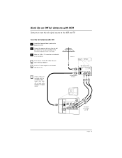
... VCR and the Antenna/Cable In jack on the VCR. 4 Connect a 75 ohm cable between the cable wall jack and the VCR In jack. Cable TV Wall Jack In Cable Box Out Output Switch 3 4 VCR Back RF Coaxial Wire (75 ohm) VCR Back AV Panel In output switch 3 4 Out ...Video Audio Typical TV Back Antenna Cable Matrix Out Component Video Input Pr Pb R Audio L Y Video In R Audio In L M.P.I. A/V cables not included with the TV. Without A/V cables, most VCRs will not play videocassettes in the illustration. No A/V cables are...
... VCR and the Antenna/Cable In jack on the VCR. 4 Connect a 75 ohm cable between the cable wall jack and the VCR In jack. Cable TV Wall Jack In Cable Box Out Output Switch 3 4 VCR Back RF Coaxial Wire (75 ohm) VCR Back AV Panel In output switch 3 4 Out ...Video Audio Typical TV Back Antenna Cable Matrix Out Component Video Input Pr Pb R Audio L Y Video In R Audio In L M.P.I. A/V cables not included with the TV. Without A/V cables, most VCRs will not play videocassettes in the illustration. No A/V cables are...

Owner's Manual
Page 17
Page 17 Hook Up Component Video Connect a component video source to the TV Component Video 1 Locate the component output jacks on the back of the DVD player. 2 Connect the component output jacks on the DVD player to the TV component input jacks, according to the connection diagram shown to the right. DVD Player with Component Video S-VIDEO OUT VIDEO R-AUDIO L-/MONO COMPONENT VIDEO OUT Y Pr Pb R L Typical TV Back Antenna Cable Matrix Out Component Video Input Pr Pb R Audio L Y Video In R Audio In L M.P.I.
Page 17 Hook Up Component Video Connect a component video source to the TV Component Video 1 Locate the component output jacks on the back of the DVD player. 2 Connect the component output jacks on the DVD player to the TV component input jacks, according to the connection diagram shown to the right. DVD Player with Component Video S-VIDEO OUT VIDEO R-AUDIO L-/MONO COMPONENT VIDEO OUT Y Pr Pb R L Typical TV Back Antenna Cable Matrix Out Component Video Input Pr Pb R Audio L Y Video In R Audio In L M.P.I.

Owner's Manual
Page 18
...Composite Audio/Video 1 Locate the composite audio/video input jacks on the back of the TV. 2 Connect the Matrix Out jack to a composite audio/video device as indicated in the illustration. Typical TV Back Antenna Cable Matrix Out Component Video Input Pr Pb R Audio L Y Video ...In R Audio In L M.P.I . Typical TV Back Antenna Cable Matrix Out Component Video Input Pr Pb R Audio L Y Video In...
...Composite Audio/Video 1 Locate the composite audio/video input jacks on the back of the TV. 2 Connect the Matrix Out jack to a composite audio/video device as indicated in the illustration. Typical TV Back Antenna Cable Matrix Out Component Video Input Pr Pb R Audio L Y Video ...In R Audio In L M.P.I . Typical TV Back Antenna Cable Matrix Out Component Video Input Pr Pb R Audio L Y Video In...
Owner's Manual
Page 19
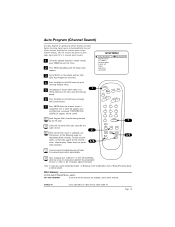
... Mini Glossary below). 6 Press the Right or Left ADJ arrow to a cable service. This is in order to a cable service, select Cable TV. Note: If necessary, select tuning band (Cable 1 or Broadcast 0) for digital channels will not work unless you subscribe to get the proper digital... information. Cable will follow the analog channel search automatically. Choose from CABLE TV to OFF AIR ANTENNA (and vice versa) it is completed. After changing from the preset label selections. 2 4/6 SETUP MENU AUTO ...
... Mini Glossary below). 6 Press the Right or Left ADJ arrow to a cable service. This is in order to a cable service, select Cable TV. Note: If necessary, select tuning band (Cable 1 or Broadcast 0) for digital channels will not work unless you subscribe to get the proper digital... information. Cable will follow the analog channel search automatically. Choose from CABLE TV to OFF AIR ANTENNA (and vice versa) it is completed. After changing from the preset label selections. 2 4/6 SETUP MENU AUTO ...

Owner's Manual
Page 20
...Auto sense source connection is turned on in the Installer menu), only the image from the front Video input will automatically change channels using the TV tuner until you have cables connected to CAMPORT, or FRNT Y/C (Front S-Video) as indicated on , you have disconnected the device. ...Captions/Text) Turns selected caption/text option on screen menus. G Video (In) Input for an S-Video signal from auxiliary equipment. A ON/OFF Typical TV Front Panel MENU CC VOL CH R-AUDIO-L VIDEO S-VIDEO C DE B F H G Typical Front Panel Controls The front Video jacks are Auto Sense...
...Auto sense source connection is turned on in the Installer menu), only the image from the front Video input will automatically change channels using the TV tuner until you have cables connected to CAMPORT, or FRNT Y/C (Front S-Video) as indicated on , you have disconnected the device. ...Captions/Text) Turns selected caption/text option on screen menus. G Video (In) Input for an S-Video signal from auxiliary equipment. A ON/OFF Typical TV Front Panel MENU CC VOL CH R-AUDIO-L VIDEO S-VIDEO C DE B F H G Typical Front Panel Controls The front Video jacks are Auto Sense...
Owner's Manual
Page 21
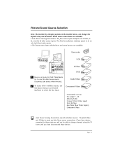
.../Sound Source Selection Note: The Installer by changing options in jacks are Auto Sense source connections. L Video In S-Video Front/Rear Connections Panels Typic al TV Bac k Matrix Out Antenna Ca b le Component Video Input Pr Pb RAud io L Y Video In R Audio In L M.P.I. 1 Hook up a ...Video Auto Source Sensing Connections override all other sources. The front Video and S-Video in the Installer menu, can change channels using the TV tuner until you have devices connected to change the default setup and determine which picture and sound sources are available. • Auto Source...
.../Sound Source Selection Note: The Installer by changing options in jacks are Auto Sense source connections. L Video In S-Video Front/Rear Connections Panels Typic al TV Bac k Matrix Out Antenna Ca b le Component Video Input Pr Pb RAud io L Y Video In R Audio In L M.P.I. 1 Hook up a ...Video Auto Source Sensing Connections override all other sources. The front Video and S-Video in the Installer menu, can change channels using the TV tuner until you have devices connected to change the default setup and determine which picture and sound sources are available. • Auto Source...
Owner's Manual
Page 22
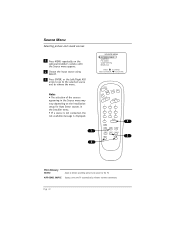
...Choose the input source using SELECT. 3 Press ENTER, or the Left/Right ADJ arrow to go to the selected source and to the TV. Page 22 Source Menu Selecting picture and sound sources 1 Press MENU repeatedly on the installation setup for Auto Sense sources in the Installer...available message is displayed. 1 3 SOURCE MENU ANTENNA/CABLE CAMPORT F S-VIDEO COMP (YPr Pb) REAR AUX. PRESS TO CHANGE PRESS ENTER OR TO ACTIVATE POWER CC TV/FM VOLUME FLSHBK MUTE CHANNEL 1 2 3 4 5 6 7 8 9 0 ENTER 3 TIMER MENU ALARM AUDIO SELECT CH PREVIEW ADJ ADJ 2 Mini Glossary SOURCE Input...
...Choose the input source using SELECT. 3 Press ENTER, or the Left/Right ADJ arrow to go to the selected source and to the TV. Page 22 Source Menu Selecting picture and sound sources 1 Press MENU repeatedly on the installation setup for Auto Sense sources in the Installer...available message is displayed. 1 3 SOURCE MENU ANTENNA/CABLE CAMPORT F S-VIDEO COMP (YPr Pb) REAR AUX. PRESS TO CHANGE PRESS ENTER OR TO ACTIVATE POWER CC TV/FM VOLUME FLSHBK MUTE CHANNEL 1 2 3 4 5 6 7 8 9 0 ENTER 3 TIMER MENU ALARM AUDIO SELECT CH PREVIEW ADJ ADJ 2 Mini Glossary SOURCE Input...


