
Owners Manual
Page 1
English CD-ROM DRIVE OWNER'S MANUAL MODEL : CRD-8240B To enjoy fully all the features and functions of your CD-ROM Drive, Please read this Owner's Manual carefully and completely.
English CD-ROM DRIVE OWNER'S MANUAL MODEL : CRD-8240B To enjoy fully all the features and functions of your CD-ROM Drive, Please read this Owner's Manual carefully and completely.
Owners Manual
Page 2
... different from that to operate the equipment. • This CD-ROM Drive is no guarantee that have installation instructions detailing user installation of fire or electric shock, do not remove cover (or back). To reduce the risk of the Canadian Interference-Causing Equipment Regulations. Refer servicing to Part 15 of the following measures: - FCC COMPLIANCE STATEMENT : Note This...
... different from that to operate the equipment. • This CD-ROM Drive is no guarantee that have installation instructions detailing user installation of fire or electric shock, do not remove cover (or back). To reduce the risk of the Canadian Interference-Causing Equipment Regulations. Refer servicing to Part 15 of the following measures: - FCC COMPLIANCE STATEMENT : Note This...
Owners Manual
Page 3
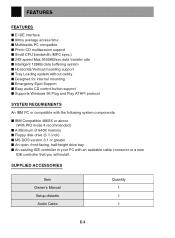
... multisession support I Small CPU bandwidth (MPC spec.) I 24X-speed Max 3600KB/sec data transfer rate I Intelligent 128KB data buffering system I Horizontal/Vertical mounting support I Tray Loading system without caddy I Designed for internal mounting I Emergency Eject Support I Easy audio CD control button support I An open, front-facing, half-height drive bay. SUPPLIED ACCESSORIES Item Owner's Manual Setup diskette Audio Cable Quantity 1 1 1 E-3 I An existing IDE controller...
... multisession support I Small CPU bandwidth (MPC spec.) I 24X-speed Max 3600KB/sec data transfer rate I Intelligent 128KB data buffering system I Horizontal/Vertical mounting support I Tray Loading system without caddy I Designed for internal mounting I Emergency Eject Support I Easy audio CD control button support I An open, front-facing, half-height drive bay. SUPPLIED ACCESSORIES Item Owner's Manual Setup diskette Audio Cable Quantity 1 1 1 E-3 I An existing IDE controller...
Owners Manual
Page 4
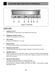
... drawer manually or when there is no power. 6. Disc Drawer Accepts a CD-ROM disc on its tray. 4. Emergency Eject Hole Insert a paper clip here to the next track. 7. Headphone Volume Control Adjusts the headphone sound level. 3. Busy Indicator The Busy Indicator lights during initialization and data-read operations. 5. If an audio CD is pressed to the drive...
... drawer manually or when there is no power. 6. Disc Drawer Accepts a CD-ROM disc on its tray. 4. Emergency Eject Hole Insert a paper clip here to the next track. 7. Headphone Volume Control Adjusts the headphone sound level. 3. Busy Indicator The Busy Indicator lights during initialization and data-read operations. 5. If an audio CD is pressed to the drive...
Owners Manual
Page 5
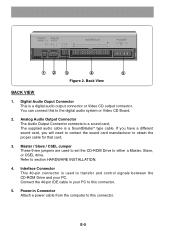
... connects to section HARDWARE INSTALLATION. 4. Master / Slave / CSEL Jumper These three jumpers are used to transfer and control signals between the CD-ROM Drive and your PC to either a Master, Slave, or CSEL drive. E-5 Digital Audio Ouput Connector This is a SoundBlaster® type cable. Power-in your PC. If... 40-pin connector is used to set the CD-ROM Drive to this connector. 5. Connect the 40-pin IDE cable in Connector Attach a power cable from the computer to this to obtain the proper cable for that card. 3. The supplied audio cable is a digital audio output connector ...
... connects to section HARDWARE INSTALLATION. 4. Master / Slave / CSEL Jumper These three jumpers are used to transfer and control signals between the CD-ROM Drive and your PC to either a Master, Slave, or CSEL drive. E-5 Digital Audio Ouput Connector This is a SoundBlaster® type cable. Power-in your PC. If... 40-pin connector is used to set the CD-ROM Drive to this connector. 5. Connect the 40-pin IDE cable in Connector Attach a power cable from the computer to this to obtain the proper cable for that card. 3. The supplied audio cable is a digital audio output connector ...

Owners Manual
Page 6
Always remove the disc before moving the drive. Avoid exposing the drive to : - This may cause a malfunction. - E-6 direct sunlight I Transportation - INSTALLATION, USAGE AND HANDLING PRECAUTIONS I Installation Avoid placing the drive in a location subject to sudden changes in temperature. I Operation - During operation, excessive vibration or a sudden jolt to the drive may cause condensation to collect inside the drive. mechanical vibration - high temperature - high humidity -
Always remove the disc before moving the drive. Avoid exposing the drive to : - This may cause a malfunction. - E-6 direct sunlight I Transportation - INSTALLATION, USAGE AND HANDLING PRECAUTIONS I Installation Avoid placing the drive in a location subject to sudden changes in temperature. I Operation - During operation, excessive vibration or a sudden jolt to the drive may cause condensation to collect inside the drive. mechanical vibration - high temperature - high humidity -
Owners Manual
Page 7
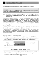
... for correct jumper settings. Figure 3. Setting MASTER / SLAVE Jumper * Move the jumper (clip on an IDE interface cable. If your system), using the above diagram to place the jumper. WARNING: To protect the CD-ROM Drive, your computer. HARDWARE INSTALLATION This section describes how to install your CD-ROM drive into your computer, and peripheral devices from damage, turn off their power before installation: The cable connecting to this service for a reasonable...
... for correct jumper settings. Figure 3. Setting MASTER / SLAVE Jumper * Move the jumper (clip on an IDE interface cable. If your system), using the above diagram to place the jumper. WARNING: To protect the CD-ROM Drive, your computer. HARDWARE INSTALLATION This section describes how to install your CD-ROM drive into your computer, and peripheral devices from damage, turn off their power before installation: The cable connecting to this service for a reasonable...
Owners Manual
Page 8
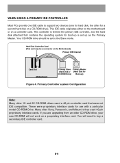
... a 40 pin controller card that contains the operating system for use with a particular model CD-ROM Drive. This IDE cable originates either on the motherboard or on the Motherboard) Primary IDE Channel Card Slot Motherboard Primary Slave Primary Master (Hard Disk or (Hard Disk for a second hard disk or a CD-ROM drive). Primary Controller system Configuration Note: Many older 1X and 2X CD...
... a 40 pin controller card that contains the operating system for use with a particular model CD-ROM Drive. This IDE cable originates either on the motherboard or on the Motherboard) Primary IDE Channel Card Slot Motherboard Primary Slave Primary Master (Hard Disk or (Hard Disk for a second hard disk or a CD-ROM drive). Primary Controller system Configuration Note: Many older 1X and 2X CD...
Owners Manual
Page 9
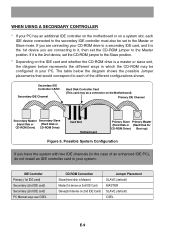
... device, set to each IDE device connected to the secondary IDE controller must also be set the CD-ROM jumper to the Slave position. * Depending on the IDE card and whether the CD-ROM drive is Master) Master(1st device on 2nd IDE Card) Slave(2nd device on the Motherboard) Primary IDE Channel Secondary Master Secondary Slave (Hard Disk or (Hard Disk or CD-ROM Drive) CD-ROM Drive) Card Slot Motherboard Primary Slave Primary Master (Hard Disk or (Hard Disk...
... device, set to each IDE device connected to the secondary IDE controller must also be set the CD-ROM jumper to the Slave position. * Depending on the IDE card and whether the CD-ROM drive is Master) Master(1st device on 2nd IDE Card) Slave(2nd device on the Motherboard) Primary IDE Channel Secondary Master Secondary Slave (Hard Disk or (Hard Disk or CD-ROM Drive) CD-ROM Drive) Card Slot Motherboard Primary Slave Primary Master (Hard Disk or (Hard Disk...
Owners Manual
Page 10
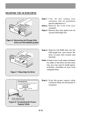
... the sides of the power-in place with screws and brackets. Power supply connector (4-pin connection cable) Figure 8. Connecting the Power Supply Cable E-10 MOUNTING THE CD-ROM DRIVE Step 1. Figure 6. Step 2. Pin assignment The pin assignment of the drive and the drive bay, you may need to install spacer brackets, available at your computer and all peripheral devices attached to it. Turn...
... the sides of the power-in place with screws and brackets. Power supply connector (4-pin connection cable) Figure 8. Connecting the Power Supply Cable E-10 MOUNTING THE CD-ROM DRIVE Step 1. Figure 6. Step 2. Pin assignment The pin assignment of the drive and the drive bay, you may need to install spacer brackets, available at your computer and all peripheral devices attached to it. Turn...
Owners Manual
Page 11
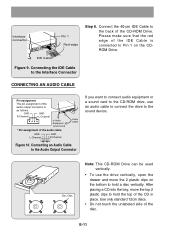
... move the top 2 plastic clips to the sound device. Disc Clips Note: This CD-ROM Drive can be used vertically. • To use an audio cable to connect the drive to hold a disc vertically. After placing a CD into the tray, move the 2 plastic clips on the CDROM Drive. Connecting the IDE Cable to the Interface Connector CONNECTING AN AUDIO...
... move the top 2 plastic clips to the sound device. Disc Clips Note: This CD-ROM Drive can be used vertically. • To use an audio cable to connect the drive to hold a disc vertically. After placing a CD into the tray, move the 2 plastic clips on the CDROM Drive. Connecting the IDE Cable to the Interface Connector CONNECTING AN AUDIO...
Owners Manual
Page 12
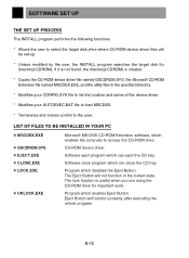
.... * Terminates and returns control to select the target disk drive where CD-ROM device driver files will be set-up. * Unless modified by the user, the INSTALL program searches the target disk for important work. SOFTWARE SET UP THE SET UP PROCESS The INSTALL program performs the following functions. * Allows the user to the user. The Eject Button will function properly after executing the unlock program...
.... * Terminates and returns control to select the target disk drive where CD-ROM device driver files will be set-up. * Unless modified by the user, the INSTALL program searches the target disk for important work. SOFTWARE SET UP THE SET UP PROCESS The INSTALL program performs the following functions. * Allows the user to the user. The Eject Button will function properly after executing the unlock program...
Owners Manual
Page 13
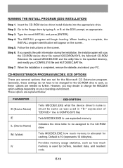
...-ROM drive Tells MSCDEX.EXE how much memory to the floppy drive by typing A: or B: at the DOS prompt, as was used by buffers, resident data, and resident code. Follow the instructions on the screen. Step 4. EXE OPTIONS There are several options that are explained below: PARAMETER /D (Device Name) /E /L: (Device Name) /M: (Value) /V DESCRIPTION Tells MSCDEX.EXE what the device driver...
...-ROM drive Tells MSCDEX.EXE how much memory to the floppy drive by typing A: or B: at the DOS prompt, as was used by buffers, resident data, and resident code. Follow the instructions on the screen. Step 4. EXE OPTIONS There are several options that are explained below: PARAMETER /D (Device Name) /E /L: (Device Name) /M: (Value) /V DESCRIPTION Tells MSCDEX.EXE what the device driver...
Owners Manual
Page 14
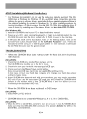
... step. 3. This CDROM drive is not present in this manual. 2. Click on the Add New Hardware icon. For other operating systems, try selecting one of the device drivers for Windows 95. Install the CD-ROM drive in your hard disk Interface type is the example installing the driver for Non-listed IDE CD-ROM . (For Windows 95) 1. Check the CD-ROM drive Master/Slave Jumper setting. TROUBLESHOOTING * When the CD-ROM drive does not...
... step. 3. This CDROM drive is not present in this manual. 2. Click on the Add New Hardware icon. For other operating systems, try selecting one of the device drivers for Windows 95. Install the CD-ROM drive in your hard disk Interface type is the example installing the driver for Non-listed IDE CD-ROM . (For Windows 95) 1. Check the CD-ROM drive Master/Slave Jumper setting. TROUBLESHOOTING * When the CD-ROM drive does not...
Owners Manual
Page 15
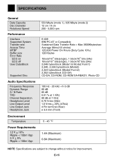
... size Error Rate ECC on ECC off User Data/Block Supported Disc Audio Specifications Frequency Response Dynamic Range S / N Ratio THD Channel Separation Headphone Level Line Output Level Line Output Jack Headphone Jack Environment Temperature Power Requirements 12 V + 10% Ripple < 100m Vpp 5 V + 5% Ripple < 100m Vpp 553 Mbyte (mode 1), 635 Mbyte (mode 2) 12 cm / 8 cm 200 - 5,000 rpm E-IDE...
... size Error Rate ECC on ECC off User Data/Block Supported Disc Audio Specifications Frequency Response Dynamic Range S / N Ratio THD Channel Separation Headphone Level Line Output Level Line Output Jack Headphone Jack Environment Temperature Power Requirements 12 V + 10% Ripple < 100m Vpp 5 V + 5% Ripple < 100m Vpp 553 Mbyte (mode 1), 635 Mbyte (mode 2) 12 cm / 8 cm 200 - 5,000 rpm E-IDE...
Owners Manual
Page 76
...ROM DRIVE English..........Page E-2 ~ E-15 Deutsch........Seite D-2 ~ D-15 Français ........Page F-2 ~ F-15 Italiano Page I-2 ~ I-15 Spanish.........Página S-2 ~ S-15 CLASS 1 KLASSE 1 LUOKAN 1 KLASS 1 LASER PRODUCT LASER PRODUKT LASER LAITE LASER APPARAT P/NO : 3828HM1009A Copyright© 1997 LG Electronics Inc. SL1 4DT LG... Electronics Deutschland GmbH Jakob Kaiser Straße 12 47877 Willich 1 GERMANY LG Goldstar France SARL 12, RUE LECH WALESA BAT.B 77322 LOGNES MARNE LA VALLEE CEDEX 2 FRANCH Printed in Korea CED N CRD-8240B CD - LG ...
...ROM DRIVE English..........Page E-2 ~ E-15 Deutsch........Seite D-2 ~ D-15 Français ........Page F-2 ~ F-15 Italiano Page I-2 ~ I-15 Spanish.........Página S-2 ~ S-15 CLASS 1 KLASSE 1 LUOKAN 1 KLASS 1 LASER PRODUCT LASER PRODUKT LASER LAITE LASER APPARAT P/NO : 3828HM1009A Copyright© 1997 LG Electronics Inc. SL1 4DT LG... Electronics Deutschland GmbH Jakob Kaiser Straße 12 47877 Willich 1 GERMANY LG Goldstar France SARL 12, RUE LECH WALESA BAT.B 77322 LOGNES MARNE LA VALLEE CEDEX 2 FRANCH Printed in Korea CED N CRD-8240B CD - LG ...


