Owners Manual
Page 6
... SAFETY INSTRUCTIONS 2 INTRODUCTION 6 Feature of this TV 6 PREPARATION Accessories 7 Front Panel Information 8 Back Panel Information 10 Back Cover for Wire Arrangement 12 Attaching the TV to a Wall 14 Stand Installation 15 VESA Wall Mounting 16 Desktop Pedestal Installation 16 Antenna or Cable Connection 17 EXTERNAL EQUIPMENT SETUP HD Receiver Setup 18 DVD Setup 21 VCR Setup 23 Other A/V Source Setup 25 PC Setup 26 AV Out Setup & Digital Audio Output 29 WATCHING TV / CHANNEL CONTROL Remote Control Key Functions 30 Turning On TV 32 Channel Selection 32 Volume Adjustment...
... SAFETY INSTRUCTIONS 2 INTRODUCTION 6 Feature of this TV 6 PREPARATION Accessories 7 Front Panel Information 8 Back Panel Information 10 Back Cover for Wire Arrangement 12 Attaching the TV to a Wall 14 Stand Installation 15 VESA Wall Mounting 16 Desktop Pedestal Installation 16 Antenna or Cable Connection 17 EXTERNAL EQUIPMENT SETUP HD Receiver Setup 18 DVD Setup 21 VCR Setup 23 Other A/V Source Setup 25 PC Setup 26 AV Out Setup & Digital Audio Output 29 WATCHING TV / CHANNEL CONTROL Remote Control Key Functions 30 Turning On TV 32 Channel Selection 32 Volume Adjustment...
Owners Manual
Page 8
... LCD screen or holding your own home. b. This means that are not sufficient cause for all models. Do not dispose of as televisions and common computer monitors. Gas in a plasma state is used in a display that is not sufficient cause for long periods of 0.9 to produce colored light (red, green, or blue). The Plasma TV Manufacturing Process: a few minute colored dots may be thought of this Plasma TV...
... LCD screen or holding your own home. b. This means that are not sufficient cause for all models. Do not dispose of as televisions and common computer monitors. Gas in a plasma state is used in a display that is not sufficient cause for long periods of 0.9 to produce colored light (red, green, or blue). The Plasma TV Manufacturing Process: a few minute colored dots may be thought of this Plasma TV...
Owners Manual
Page 10
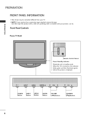
... from your product has a protection tape attached, remove the tape. When the TV is turned on, the indicator blinks green and then illuminates green before the picture is included with your product, use it). And then wipe the product with a cloth (If a polishing cloth is displayed. INPUT MENU ENTER VOL CH INPUT MENU ENTER VOL CH POWER Button INPUT Button MENU Button ENTER Button VOLUME (F,G)Buttons CHANNEL (E,D)Buttons 8 Front Panel Controls Plasma TV Model PREPARATION Remote Control Sensor Power/Standby Indicator Illuminates red in standby mode.
... from your product has a protection tape attached, remove the tape. When the TV is turned on, the indicator blinks green and then illuminates green before the picture is included with your product, use it). And then wipe the product with a cloth (If a polishing cloth is displayed. INPUT MENU ENTER VOL CH INPUT MENU ENTER VOL CH POWER Button INPUT Button MENU Button ENTER Button VOLUME (F,G)Buttons CHANNEL (E,D)Buttons 8 Front Panel Controls Plasma TV Model PREPARATION Remote Control Sensor Power/Standby Indicator Illuminates red in standby mode.
Owners Manual
Page 18
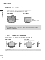
... VESA Wall Mounting Instruction Guide. ( ) ( ) DESKTOP PEDESTAL INSTALLATION For proper ventilation, allow a clearance of 4inches on the wall mount used. NOTE G Screw length needed depends on all four sides from the wall. Plasma TV Model LCD TV Model 4 inches 4 inches 4 inches 4 inches 4 inches 4 inches 4 inches 4 inches CAUTION G Ensure adequate ventilation by following the clearance recommendations. 16 Plasma TV Model 600 mm LCD TV Model 600 mm (32 inches only: 200 mm) R R 400 mm 400 mm (32 inches only: 100 mm) ! PREPARATION PREPARATION VESA WALL MOUNTING This...
... VESA Wall Mounting Instruction Guide. ( ) ( ) DESKTOP PEDESTAL INSTALLATION For proper ventilation, allow a clearance of 4inches on the wall mount used. NOTE G Screw length needed depends on all four sides from the wall. Plasma TV Model LCD TV Model 4 inches 4 inches 4 inches 4 inches 4 inches 4 inches 4 inches 4 inches CAUTION G Ensure adequate ventilation by following the clearance recommendations. 16 Plasma TV Model 600 mm LCD TV Model 600 mm (32 inches only: 200 mm) R R 400 mm 400 mm (32 inches only: 100 mm) ! PREPARATION PREPARATION VESA WALL MOUNTING This...

Owners Manual
Page 20
... IN2 input, select Component 2 input source. However, if you have finished connecting all equipment. How to use picture for the digital set-top box. How to connect 1 Connect the video outputs (Y, PB, PR) of EXTERNAL EQUIPMENT SETUP mainly use I Turn on the set. I This part of the digital set top box to the COMPONENT IN VIDEO 1 jacks on the digital set-top box. (Refer to the owner's manual for LCD TV model. Match the jack colors (Y = green, PB = blue, and PR = red). When connecting Component cable 1. COMPONENT...
... IN2 input, select Component 2 input source. However, if you have finished connecting all equipment. How to use picture for the digital set-top box. How to connect 1 Connect the video outputs (Y, PB, PR) of EXTERNAL EQUIPMENT SETUP mainly use I Turn on the set. I This part of the digital set top box to the COMPONENT IN VIDEO 1 jacks on the digital set-top box. (Refer to the owner's manual for LCD TV model. Match the jack colors (Y = green, PB = blue, and PR = red). When connecting Component cable 1. COMPONENT...
Owners Manual
Page 21
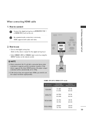
EXTERNAL EQUIPMENT SETUP When connecting HDMI cable 1. NOTE G When connected, the TV will be automatically set . 2 No separated audio connection is necessary. G If the device does not support Auto HDMI, you need to set -top box.) I Turn on the set to the owner's manual for the digital set the output resolution appropriately. How to use I Select HDMI1/DVI or HDMI2 input source by using the INPUT button on the remote control. ! SERVICE RGB IN (PC) ANTENNA/ CABLE IN HDMI IN 2 1 HDMI/DVI IN AUDIO IN REMOTE (RGB/DVI) CONTROL IN RS-232C IN (CONTROL & SERVICE) 1 HDMI-DTV...
EXTERNAL EQUIPMENT SETUP When connecting HDMI cable 1. NOTE G When connected, the TV will be automatically set . 2 No separated audio connection is necessary. G If the device does not support Auto HDMI, you need to set -top box.) I Turn on the set to the owner's manual for the digital set the output resolution appropriately. How to use I Select HDMI1/DVI or HDMI2 input source by using the INPUT button on the remote control. ! SERVICE RGB IN (PC) ANTENNA/ CABLE IN HDMI IN 2 1 HDMI/DVI IN AUDIO IN REMOTE (RGB/DVI) CONTROL IN RS-232C IN (CONTROL & SERVICE) 1 HDMI-DTV...
Owners Manual
Page 22
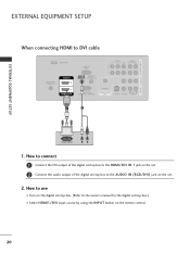
... to use I Turn on the digital set-top box. (Refer to the owner's manual for the digital set-top box.) I Select HDMI1/DVI input source by using the INPUT button on the set -top box to DVI cable SERVICE RGB IN (PC) VIDEO AUDIO ANTENNA/ CABLE IN HDMI IN 2 1 HDMI/DVI IN AUDIO IN REMOTE (RGB/DVI) CONTROL IN RS-232C IN (CONTROL & SERVICE) OPTICAL DIGITAL AUDIO OUT S-VIDEO VIDEO (MONO) AUDIO 1 2 DVI-DTV OUTPUT L R 1. How to connect 1 Connect the DVI output of the digital set-top box to the HDMI/DVI IN 1 jack on the set. 2 Connect the audio output of the digital set . 2. COMPONENT...
... to use I Turn on the digital set-top box. (Refer to the owner's manual for the digital set-top box.) I Select HDMI1/DVI input source by using the INPUT button on the set -top box to DVI cable SERVICE RGB IN (PC) VIDEO AUDIO ANTENNA/ CABLE IN HDMI IN 2 1 HDMI/DVI IN AUDIO IN REMOTE (RGB/DVI) CONTROL IN RS-232C IN (CONTROL & SERVICE) OPTICAL DIGITAL AUDIO OUT S-VIDEO VIDEO (MONO) AUDIO 1 2 DVI-DTV OUTPUT L R 1. How to connect 1 Connect the DVI output of the digital set-top box to the HDMI/DVI IN 1 jack on the set. 2 Connect the audio output of the digital set . 2. COMPONENT...

Owners Manual
Page 23
I Turn on the remote control. Component ports on the TV Y PB PR Video output ports on the set . EXTERNAL EQUIPMENT SETUP COMPONENT IN AV OUT AV IN 1 DVD SETUP When connecting Component cable 1. Match the jack colors (Y = green, PB = blue, and PR = red). 2 Connect the audio outputs of the DVD to use I Refer to COMPONENT IN 2 input, select Component 2 input source. I If connected to the DVD player's manual for operating instructions. How to the COMPONENT IN VIDEO1 jacks on the set . 2. I Select Component 1 input source by...
I Turn on the remote control. Component ports on the TV Y PB PR Video output ports on the set . EXTERNAL EQUIPMENT SETUP COMPONENT IN AV OUT AV IN 1 DVD SETUP When connecting Component cable 1. Match the jack colors (Y = green, PB = blue, and PR = red). 2 Connect the audio outputs of the DVD to use I Refer to COMPONENT IN 2 input, select Component 2 input source. I If connected to the DVD player's manual for operating instructions. How to the COMPONENT IN VIDEO1 jacks on the set . 2. I Select Component 1 input source by...

Owners Manual
Page 24
...A V 1 input source by using the INPUT button on the DVD player, insert a DVD. S-VIDEO AUDIO L R VIDEO 1 AUDIO 2 OPTICAL DIGITAL AUDIO OUT S-VIDEO VIDEO (MONO) AUDIO SERVICE RGB IN (PC) ANTENNA/ CABLE IN HDMI IN 2 1 HDMI/DVI IN AUDIO IN REMOT (RGB/DVI) CONTROL RS-232C IN (CONTROL & SERVICE ! To get the best picture quality, adjust the output resolution of the DVD to AV IN2, select A V 2 input source. I If connected to 720p. 22 1 HDMI-DVD OUTPUT I Refer to the DVD player's manual for operating instructions. G If the device does not support Auto HDMI, you need to set...
...A V 1 input source by using the INPUT button on the DVD player, insert a DVD. S-VIDEO AUDIO L R VIDEO 1 AUDIO 2 OPTICAL DIGITAL AUDIO OUT S-VIDEO VIDEO (MONO) AUDIO SERVICE RGB IN (PC) ANTENNA/ CABLE IN HDMI IN 2 1 HDMI/DVI IN AUDIO IN REMOT (RGB/DVI) CONTROL RS-232C IN (CONTROL & SERVICE ! To get the best picture quality, adjust the output resolution of the DVD to AV IN2, select A V 2 input source. I If connected to 720p. 22 1 HDMI-DVD OUTPUT I Refer to the DVD player's manual for operating instructions. G If the device does not support Auto HDMI, you need to set...
Owners Manual
Page 25
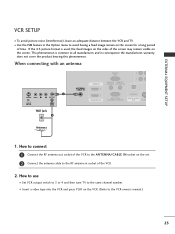
... time. I Set VCR output switch to 3 or 4 and then tune TV to the same channel number. If the 4:3 picture format is common to all manufactures and in socket of the VCR to the ANTENNA/CABLE IN socket on the screen. When connecting with an antenna 1 S-VIDEO VIDEO L R ANT OUT OUTPUT SWITCH ANT IN Wall Jack 2 RGB IN (PC) ANTENNA/ CABLE IN HDMI IN 2 1 HDMI/DVI IN AUDIO IN REMOTE (RGB/DVI) CONTROL IN RS-232C IN (CONTROL & SERVICE) OPTICAL DIGITAL AUDIO OUT S-VID Antenna 1. EXTERNAL...
... time. I Set VCR output switch to 3 or 4 and then tune TV to the same channel number. If the 4:3 picture format is common to all manufactures and in socket of the VCR to the ANTENNA/CABLE IN socket on the screen. When connecting with an antenna 1 S-VIDEO VIDEO L R ANT OUT OUTPUT SWITCH ANT IN Wall Jack 2 RGB IN (PC) ANTENNA/ CABLE IN HDMI IN 2 1 HDMI/DVI IN AUDIO IN REMOTE (RGB/DVI) CONTROL IN RS-232C IN (CONTROL & SERVICE) OPTICAL DIGITAL AUDIO OUT S-VID Antenna 1. EXTERNAL...

Owners Manual
Page 26
...OUT OUTPUT SWITCH VIDEO AUDIO 1 N OPTICAL DIGITAL AUDIO OUT S-VIDEO VIDEO (MONO) AUDIO ! How to normal composite (RCA cable) input. When connecting with a RCA cable 1. How to use I Insert a video tape into the VCR and press PLAY on the VCR. (Refer to the VCR owner's manual.) I Select A V 1 input source by using the INPUT button on the remote control. I If connected to the VCR owner's manual.) I Select A V 1 input source by using the INPUT button on the remote control. I If connected to both Video and the S-Video cables, only the S-Video will work. 24...
...OUT OUTPUT SWITCH VIDEO AUDIO 1 N OPTICAL DIGITAL AUDIO OUT S-VIDEO VIDEO (MONO) AUDIO ! How to normal composite (RCA cable) input. When connecting with a RCA cable 1. How to use I Insert a video tape into the VCR and press PLAY on the VCR. (Refer to the VCR owner's manual.) I Select A V 1 input source by using the INPUT button on the remote control. I If connected to the VCR owner's manual.) I Select A V 1 input source by using the INPUT button on the remote control. I If connected to both Video and the S-Video cables, only the S-Video will work. 24...

Owners Manual
Page 28
When connecting HDMI to the TV's settings. Connect the PC audio output to use I Turn on the set . RGB IN (PC) HDMI IN 2 1 HDMI/DVI IN AUDIO IN REMOTE (RGB/DVI) CONTROL IN RS-232C IN (CONTROL & SERVICE) OPTICAL DIGITAL AUDIO OUT 1 2 AUDIO RGB OUTPUT RGB IN (PC) ANTENNA/ CABLE IN HDMI IN 2 1 HDMI/DVI IN AUDIO IN REMOTE (RGB/DVI) CONTROL RS-232C IN (CONTROL & SERVICE 2. When connecting D-sub 15pin cable 1. How to the AUDIO IN 2 (RGB/DVI) jack on the PC and the TV. I Select HDMI1/DVI input source by using the INPUT button on...
When connecting HDMI to the TV's settings. Connect the PC audio output to use I Turn on the set . RGB IN (PC) HDMI IN 2 1 HDMI/DVI IN AUDIO IN REMOTE (RGB/DVI) CONTROL IN RS-232C IN (CONTROL & SERVICE) OPTICAL DIGITAL AUDIO OUT 1 2 AUDIO RGB OUTPUT RGB IN (PC) ANTENNA/ CABLE IN HDMI IN 2 1 HDMI/DVI IN AUDIO IN REMOTE (RGB/DVI) CONTROL RS-232C IN (CONTROL & SERVICE 2. When connecting D-sub 15pin cable 1. How to the AUDIO IN 2 (RGB/DVI) jack on the PC and the TV. I Select HDMI1/DVI input source by using the INPUT button on...

Owners Manual
Page 30
... use D or E button to select Resolution, Position, Size, or Phase. 2 Press the ENTER button and then use F or G button to PC input and checking the screen quality. When HDMI/DVI connect to PC output and select HDMI/DVI input, this function is -30 ~ +30. PICTURE SOUND SAP CC ADJUST Resolution Position Size Phase 1024 x 768 1280 x 768 1360 x 768 1366 x 768 Reset D MENU Close FG E Move Ok 123 Resolution This function allows you to remove any vertical...
... use D or E button to select Resolution, Position, Size, or Phase. 2 Press the ENTER button and then use F or G button to PC input and checking the screen quality. When HDMI/DVI connect to PC output and select HDMI/DVI input, this function is -30 ~ +30. PICTURE SOUND SAP CC ADJUST Resolution Position Size Phase 1024 x 768 1280 x 768 1360 x 768 1366 x 768 Reset D MENU Close FG E Move Ok 123 Resolution This function allows you to remove any vertical...
Owners Manual
Page 31
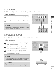
... the optical cable to hook up the second TV or monitor. 1. NOTE G When connecting with external audio equipments, such as amplifiers or speakers, please turn the TV speakers off. (G p.57) CAUTION G Do not look into the optical output port. NOTE G Component1-2, RGB-PC, HDMI1/DVI, HDMI2, DTV input sources cannot be used for further details regarding that device's input settings. ! Off" in the AUDIO menu. (G p.57). ICAL L AUDIO UT S-VIDEO VIDEO (MONO) AUDIO 1 VIDEO L R S-VIDEO DIGITAL AUDIO OUTPUT Send the TV's audio to the TV...
... the optical cable to hook up the second TV or monitor. 1. NOTE G When connecting with external audio equipments, such as amplifiers or speakers, please turn the TV speakers off. (G p.57) CAUTION G Do not look into the optical output port. NOTE G Component1-2, RGB-PC, HDMI1/DVI, HDMI2, DTV input sources cannot be used for further details regarding that device's input settings. ! Off" in the AUDIO menu. (G p.57). ICAL L AUDIO UT S-VIDEO VIDEO (MONO) AUDIO 1 VIDEO L R S-VIDEO DIGITAL AUDIO OUTPUT Send the TV's audio to the TV...

Owners Manual
Page 34
At this moment, the TV switches to select a channel number. I In standby mode to turn TV on, press the , INPUT, CH (D or E) button on the TV or press the POWER, INPUT, TV INPUT, CH(D or E), Number (0~9) button on vacation, disconnect the power plug from the wall power outlet. TV INPUT POWER DVD TV MODE INPUT VCR EXIT TIMER RATIO SIMPLINK VOL MUTE FAV CH 1 2 3 4 5 6 7 8 9 0 BACK PICTURE SOUND SAP CC WATCHING TV / CHANNEL CONTROL ! I This TV is out. 3 When finished using the TV INPUT, INPUT button on the remote control. CHANNEL SELECTION 1 Press the CH...
At this moment, the TV switches to select a channel number. I In standby mode to turn TV on, press the , INPUT, CH (D or E) button on the TV or press the POWER, INPUT, TV INPUT, CH(D or E), Number (0~9) button on vacation, disconnect the power plug from the wall power outlet. TV INPUT POWER DVD TV MODE INPUT VCR EXIT TIMER RATIO SIMPLINK VOL MUTE FAV CH 1 2 3 4 5 6 7 8 9 0 BACK PICTURE SOUND SAP CC WATCHING TV / CHANNEL CONTROL ! I This TV is out. 3 When finished using the TV INPUT, INPUT button on the remote control. CHANNEL SELECTION 1 Press the CH...
Owners Manual
Page 35
... use D E F G button to display the available menus. SETUP EZ Scan Manual Scan Channel Edit DTV Signal Input Source Input Label Set ID VIDEO EZ Picture Color Temperature XD Advanced Video Reset WATCHING TV / CHANNEL CONTROL LOCK For USA Lock System Set Password Block Channel Movie Rating TV Rating-Children TV Rating-General Downloadable Rating Input Block For Canada Lock System Set Password Block Channel TV Rating-English TV Rating-French Downloadable Rating Input Block OPTION Aspect Ratio Caption/Text Caption Option Language ISM Method Low Power SimpLink Plasma TV model only AUDIO...
... use D E F G button to display the available menus. SETUP EZ Scan Manual Scan Channel Edit DTV Signal Input Source Input Label Set ID VIDEO EZ Picture Color Temperature XD Advanced Video Reset WATCHING TV / CHANNEL CONTROL LOCK For USA Lock System Set Password Block Channel Movie Rating TV Rating-Children TV Rating-General Downloadable Rating Input Block For Canada Lock System Set Password Block Channel TV Rating-English TV Rating-French Downloadable Rating Input Block OPTION Aspect Ratio Caption/Text Caption Option Language ISM Method Low Power SimpLink Plasma TV model only AUDIO...

Owners Manual
Page 36
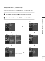
... Signal Input Source Input Label Set ID EZ Scan Manual Scan Channel Edit DTV Signal Input Source Input Label Set ID 1 G Selection ( G or ) leads you to the EZ scan screen. A password is required to gain access to EZ Scan menu if the Lock System is turned on the channel list. WATCHING TV / CHANNEL CONTROL WATCHING TV / CHANNEL CONTROL CHANNEL SEARCH Auto Scan (EZ Scan) Automatically finds all channels available through antenna or cable inputs, and stores them in memory on . 1 Press the MENU button and then use D or E button to select the SETUP menu...
... Signal Input Source Input Label Set ID EZ Scan Manual Scan Channel Edit DTV Signal Input Source Input Label Set ID 1 G Selection ( G or ) leads you to the EZ scan screen. A password is required to gain access to EZ Scan menu if the Lock System is turned on the channel list. WATCHING TV / CHANNEL CONTROL WATCHING TV / CHANNEL CONTROL CHANNEL SEARCH Auto Scan (EZ Scan) Automatically finds all channels available through antenna or cable inputs, and stores them in memory on . 1 Press the MENU button and then use D or E button to select the SETUP menu...
Owners Manual
Page 71
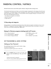
... 69 I TV-Y7 (Children 7 years older) SET PASSWORD & LOCK SYSTEM Setting up Your Password Set up with the initial password "0-0-0-0". Specify a password 3. Set ratings and categories to block all programs to select the LOCK menu. PARENTAL CONTROL / RATINGS Parental Control can be used to block program viewing based on the ratings sent by the broadcasting station. I Enter the password as requested. It is set up blocking schemes to block specific channels, ratings, and external viewing sources.
... 69 I TV-Y7 (Children 7 years older) SET PASSWORD & LOCK SYSTEM Setting up Your Password Set up with the initial password "0-0-0-0". Specify a password 3. Set ratings and categories to block all programs to select the LOCK menu. PARENTAL CONTROL / RATINGS Parental Control can be used to block program viewing based on the ratings sent by the broadcasting station. I Enter the password as requested. It is set up blocking schemes to block specific channels, ratings, and external viewing sources.
Owners Manual
Page 82
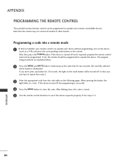
... MENU and MUTE button continuously at a time. APPENDIX 80 If not, the remote should be programmed to operate most remote-controllable devices. the currently selected device button is successful. 4 Press the MENU button to store the code. If not, steps 2-5. The program- If the device turned off, the programming is illuminated. Programming a code into a remote mode 1 To find out whether your remote control can be programmed. If the device is stored. 5 Test the remote control...
... MENU and MUTE button continuously at a time. APPENDIX 80 If not, the remote should be programmed to operate most remote-controllable devices. the currently selected device button is successful. 4 Press the MENU button to store the code. If not, steps 2-5. The program- If the device turned off, the programming is illuminated. Programming a code into a remote mode 1 To find out whether your remote control can be programmed. If the device is stored. 5 Test the remote control...
Owners Manual
Page 90
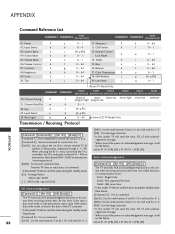
... COMMAND2 DATA (Hexadecimal) 01. Power k 02. Input Select k 03. Aspect Ratio k 04. Brightness k 09. Color k 10. Tint k a 0~1 11. Remote Control d 0~1 Lock Mode k e 0~1 14. Treble k f 0 ~ 64 15. Low Power j k 0 ~ 64 l 0~1 m 0~1 r 0 ~ 64 s 0 ~ 64 t 0 ~ 64 u 0~3 p (G p.90) q 0~1 Plasma TV Model Only COMMAND1 COMMAND2 20. Channel Add/Del m b 22. When selecting Set ID '0', every connected the TV is data read status of the PC computer. [DATA] : Use the small character, if...
... COMMAND2 DATA (Hexadecimal) 01. Power k 02. Input Select k 03. Aspect Ratio k 04. Brightness k 09. Color k 10. Tint k a 0~1 11. Remote Control d 0~1 Lock Mode k e 0~1 14. Treble k f 0 ~ 64 15. Low Power j k 0 ~ 64 l 0~1 m 0~1 r 0 ~ 64 s 0 ~ 64 t 0 ~ 64 u 0~3 p (G p.90) q 0~1 Plasma TV Model Only COMMAND1 COMMAND2 20. Channel Add/Del m b 22. When selecting Set ID '0', every connected the TV is data read status of the PC computer. [DATA] : Use the small character, if...


