Owners Manual
Page 2
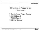
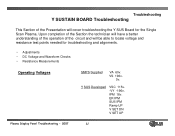
Troubleshooting Overview of Topics to be Discussed •Switch Mode Power Supply •Y SUS Board •Z SUS Board •X Drive Boards Plasma Display Panel Troubleshooting - 2007 2
Troubleshooting Overview of Topics to be Discussed •Switch Mode Power Supply •Y SUS Board •Z SUS Board •X Drive Boards Plasma Display Panel Troubleshooting - 2007 2
Owners Manual
Page 3
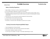
... on screen. Be cautious of short circuit when measuring voltage. 7. Checking Point before adjustment. 2. Check details of Panel and boards. 2. Plasma Display Panel Troubleshooting - 2007 3 Check the model label. Safety Rules PLASMA Overview Safety & Handling Regulations Troubleshooting 1. Approximately 10 minute pre-run time is required for at least one minute because of...
... on screen. Be cautious of short circuit when measuring voltage. 7. Checking Point before adjustment. 2. Check details of Panel and boards. 2. Plasma Display Panel Troubleshooting - 2007 3 Check the model label. Safety Rules PLASMA Overview Safety & Handling Regulations Troubleshooting 1. Approximately 10 minute pre-run time is required for at least one minute because of...

Owners Manual
Page 4
... to the sticker located in the upper right side of the Power Supply circuit and will vary from Panel to Panel. V SET_UP -VY VSC Z_BIAS Plasma Display Panel Troubleshooting - 2007 4 Upon completion of the section the technician will have a better understanding of the operation of the PDP for the correct voltage...
... to the sticker located in the upper right side of the Power Supply circuit and will vary from Panel to Panel. V SET_UP -VY VSC Z_BIAS Plasma Display Panel Troubleshooting - 2007 4 Upon completion of the section the technician will have a better understanding of the operation of the PDP for the correct voltage...
Owners Manual
Page 5
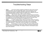
... bumps" will be the DC Supply voltages to the Customer. Capacitors will sometimes leak dielectric material and give off a distinct odor. Frequency of the failure. Plasma Display Panel Troubleshooting - 2007 5 Troubleshooting Steps • Define Look at the symptom carefully and determine what circuits could be sure they are missing check the...
... bumps" will be the DC Supply voltages to the Customer. Capacitors will sometimes leak dielectric material and give off a distinct odor. Frequency of the failure. Plasma Display Panel Troubleshooting - 2007 5 Troubleshooting Steps • Define Look at the symptom carefully and determine what circuits could be sure they are missing check the...

Owners Manual
Page 6
The SMPS outputs S 5v (Standby). Power Sequence • AC Cord Plugged in Standby Mode when turned off for TVGOS Data. • Standby Operation - Plasma Display Panel Troubleshooting - 2007 6 The unit can be taken out of DS Mode as needed for approximately 2 hours and go into Deep Sleep Mode. Needed ...
The SMPS outputs S 5v (Standby). Power Sequence • AC Cord Plugged in Standby Mode when turned off for TVGOS Data. • Standby Operation - Plasma Display Panel Troubleshooting - 2007 6 The unit can be taken out of DS Mode as needed for approximately 2 hours and go into Deep Sleep Mode. Needed ...
Owners Manual
Page 7
... 10 of connector P804 to chassis ground. Measured from pins 1 and 2 of Deep Sleep Mode. • 5V-M Needed to chassis ground. Adjusted at pins 1 and 2. Plasma Display Panel Troubleshooting - 2007 7 Adjusted at P800 pin 3 applied to the Analog Board and used for the signal processing circuits present in standby. Measured at...
... 10 of connector P804 to chassis ground. Measured from pins 1 and 2 of Deep Sleep Mode. • 5V-M Needed to chassis ground. Adjusted at pins 1 and 2. Plasma Display Panel Troubleshooting - 2007 7 Adjusted at P800 pin 3 applied to the Analog Board and used for the signal processing circuits present in standby. Measured at...
Owners Manual
Page 8
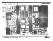
Power Supply VS Adjust VA Adjust VS VA Source VA 5v VS Source Control IC 3.3v Adjust 19v Audio Supply 12V,6V, 5V and 3.3V Source Standby Circuit P802 P803 P800 Plasma Display Panel Troubleshooting - 2007 8 Troubleshooting 380 Volt Supply AC Input Circuit
Power Supply VS Adjust VA Adjust VS VA Source VA 5v VS Source Control IC 3.3v Adjust 19v Audio Supply 12V,6V, 5V and 3.3V Source Standby Circuit P802 P803 P800 Plasma Display Panel Troubleshooting - 2007 8 Troubleshooting 380 Volt Supply AC Input Circuit
Owners Manual
Page 9
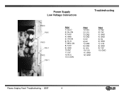
Power Supply Low Voltage Connectors Troubleshooting P800 PIN1 P803 PIN 1 P802 PIN 1 P800 1) AC-D 2) RL-ON 3) S-5V 4) GND 5) VS-ON 6) 5V-D 7) M5V-ON 8) S-5V 9) GND 10) NC 11) 6V 12) N.C 13) 3.3ON P803 1) 3.3V 2) 3.3V 3) GND 4) GND 5) 6V 6) 6V 7) GND 8) GND 9) 12V 10) 12V 11) GND 12) GND P802 1) 19V 2) 19V 3) GND 4) GND 5) 6V 6) GND 7) 3.3V 8) GND 9) 12V 10) GND Plasma Display Panel Troubleshooting - 2007 9
Power Supply Low Voltage Connectors Troubleshooting P800 PIN1 P803 PIN 1 P802 PIN 1 P800 1) AC-D 2) RL-ON 3) S-5V 4) GND 5) VS-ON 6) 5V-D 7) M5V-ON 8) S-5V 9) GND 10) NC 11) 6V 12) N.C 13) 3.3ON P803 1) 3.3V 2) 3.3V 3) GND 4) GND 5) 6V 6) 6V 7) GND 8) GND 9) 12V 10) 12V 11) GND 12) GND P802 1) 19V 2) 19V 3) GND 4) GND 5) 6V 6) GND 7) 3.3V 8) GND 9) 12V 10) GND Plasma Display Panel Troubleshooting - 2007 9
Owners Manual
Page 10
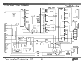
... D951 VS D952 D953 D271 6V D261 Q252 D251 D202 VA 5V-M Q281 5V HS6 U261 Q223 D221 3.3v AC Input F101 AC INPUT Circuit Plasma Display Panel Troubleshooting - 2007 10 Power Supply Voltage Distribution HS2 Q607 Q801 PC901 HS3 U801 HS4 T801 R606 R607 Q606 Q601 U851 T902 Q854 R963...
... D951 VS D952 D953 D271 6V D261 Q252 D251 D202 VA 5V-M Q281 5V HS6 U261 Q223 D221 3.3v AC Input F101 AC INPUT Circuit Plasma Display Panel Troubleshooting - 2007 10 Power Supply Voltage Distribution HS2 Q607 Q801 PC901 HS3 U801 HS4 T801 R606 R607 Q606 Q601 U851 T902 Q854 R963...
Owners Manual
Page 11
... will have a better understanding of the operation of the Presentation will be able to locate voltage and resistance test points needed for the Single Scan Plasma. ER IPM SUS IPM Ramp UP V SET DN V SET UP...
... will have a better understanding of the operation of the Presentation will be able to locate voltage and resistance test points needed for the Single Scan Plasma. ER IPM SUS IPM Ramp UP V SET DN V SET UP...
Owners Manual
Page 12
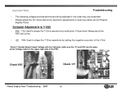
... sure the -VY and VSC are presented. • Always adjust the DC levels before the waveform adjustments to most accurately set the Plasma Display Panel. Check VSC Check -VY Plasma Display Panel Troubleshooting - 2007 12 Important Note Troubleshooting • The following voltages and waveforms should be adjusted in the order they are...
... sure the -VY and VSC are presented. • Always adjust the DC levels before the waveform adjustments to most accurately set the Plasma Display Panel. Check VSC Check -VY Plasma Display Panel Troubleshooting - 2007 12 Important Note Troubleshooting • The following voltages and waveforms should be adjusted in the order they are...

Owners Manual
Page 13
Troubleshooting Waveform Adjustments Y SUSTAIN • Ramp Up Used to shape the Y Drive Waveform by changing the pitch of the Top Ramp • V SET DN Used to shape the Y Drive Waveform by changing the pitch of the Bottom Ramp • V SET UP Used to shape the Y Drive waveform by leveling the Top Ramp Plasma Display Panel Troubleshooting - 2007 13
Troubleshooting Waveform Adjustments Y SUSTAIN • Ramp Up Used to shape the Y Drive Waveform by changing the pitch of the Top Ramp • V SET DN Used to shape the Y Drive Waveform by changing the pitch of the Bottom Ramp • V SET UP Used to shape the Y Drive waveform by leveling the Top Ramp Plasma Display Panel Troubleshooting - 2007 13
Owners Manual
Page 14
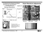
Ground VSET DN +VSC Plasma Display Panel Troubleshooting - 2007 14 Readings are taken with different Y_SUSTAIN PCB part #'s. Normal Waveform RAMP UP Panel Waveform Adjustment 35 micro seconds Scope TP 000 -VY 180 micro seconds VSET UP This test point is the reference for all the following signals referred to 10x1. Troubleshooting Single Scan Panel *Waveforms may vary with the probe set to here.
Ground VSET DN +VSC Plasma Display Panel Troubleshooting - 2007 14 Readings are taken with different Y_SUSTAIN PCB part #'s. Normal Waveform RAMP UP Panel Waveform Adjustment 35 micro seconds Scope TP 000 -VY 180 micro seconds VSET UP This test point is the reference for all the following signals referred to 10x1. Troubleshooting Single Scan Panel *Waveforms may vary with the probe set to here.

Owners Manual
Page 15
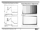
Troubleshooting Single Scan Panel Panel Waveform Adjustment Ramp up too low Plasma Display Panel Troubleshooting - 2007 Noticeable low level color distortion with the Ramp_up too high. Ramp up too high Noticeable low level color distortion with the Ramp_up too low. 15
Troubleshooting Single Scan Panel Panel Waveform Adjustment Ramp up too low Plasma Display Panel Troubleshooting - 2007 Noticeable low level color distortion with the Ramp_up too high. Ramp up too high Noticeable low level color distortion with the Ramp_up too low. 15
Owners Manual
Page 16
Vset DN too high Plasma Display Panel Troubleshooting - 2007 All of the center washes out due to decreased Vset DN time. Troubleshooting Single Scan Panel Panel Waveform Adjustment Vset DN too low The center begins to wash out and arc due to increased Vset_DN time. 16
Vset DN too high Plasma Display Panel Troubleshooting - 2007 All of the center washes out due to decreased Vset DN time. Troubleshooting Single Scan Panel Panel Waveform Adjustment Vset DN too low The center begins to wash out and arc due to increased Vset_DN time. 16

Owners Manual
Page 17
The peek widens due to the picture, the wave form indicates a distorted Vset UP. Vset UP too low Plasma Display Panel Troubleshooting - 2007 Very little alteration to the Vset UP peeking too quickly. 17 Troubleshooting Single Scan Panel Panel Waveform Adjustment Vset UP too high The center begins to wash out and arc due to Vset UP Peeking too late and alters the start of the Vset DN phase.
The peek widens due to the picture, the wave form indicates a distorted Vset UP. Vset UP too low Plasma Display Panel Troubleshooting - 2007 Very little alteration to the Vset UP peeking too quickly. 17 Troubleshooting Single Scan Panel Panel Waveform Adjustment Vset UP too high The center begins to wash out and arc due to Vset UP Peeking too late and alters the start of the Vset DN phase.
Owners Manual
Page 18
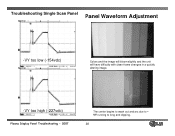
VY running to - Troubleshooting Single Scan Panel Panel Waveform Adjustment -VY too low (-154vdc) Colors and the image will bloom slightly and the unit will have difficulty with clean frame changes in a quickly altering image. -VY too high (-227vdc) Plasma Display Panel Troubleshooting - 2007 The center begins to wash out and arc due to long and clipping. 18
VY running to - Troubleshooting Single Scan Panel Panel Waveform Adjustment -VY too low (-154vdc) Colors and the image will bloom slightly and the unit will have difficulty with clean frame changes in a quickly altering image. -VY too high (-227vdc) Plasma Display Panel Troubleshooting - 2007 The center begins to wash out and arc due to long and clipping. 18

Owners Manual
Page 19
Troubleshooting Single Scan Panel Panel Waveform Adjustment VSC too low (77 Volts) The image will show very little change but there will Be some distortion in a quickly changing image. VSC too high (140 Volts) Plasma Display Panel Troubleshooting - 2007 The image will show very little change but there will Be some distortion in a quickly changing image. 19
Troubleshooting Single Scan Panel Panel Waveform Adjustment VSC too low (77 Volts) The image will show very little change but there will Be some distortion in a quickly changing image. VSC too high (140 Volts) Plasma Display Panel Troubleshooting - 2007 The image will show very little change but there will Be some distortion in a quickly changing image. 19

Owners Manual
Page 20
Plasma Display Panel Troubleshooting - 2007 20 SINGLE SCAN PDP 50PX3 DVM ZBIAS adjustment: On the Z-Sustain PCB With the DVM across R92 adjust the potentiometer till the DVM reads 93 vdc.
Plasma Display Panel Troubleshooting - 2007 20 SINGLE SCAN PDP 50PX3 DVM ZBIAS adjustment: On the Z-Sustain PCB With the DVM across R92 adjust the potentiometer till the DVM reads 93 vdc.
Owners Manual
Page 21
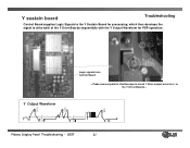
Logic signals from Control Board < Probe connect point to Oscilloscope to check Y Drive output wave form to drive both of the Y Drive Boards sequentially with the Y Output Waveform for processing, which then develops the signal to the Y Driver Boards > 110V 200V 110V 200V 80V Y Output Waveform V Y s Plasma Display Panel Troubleshooting - 2007 21 Y sustain board Troubleshooting Control Board supplies Logic Signals to the Y Sustain Board for PDP operation.
Logic signals from Control Board < Probe connect point to Oscilloscope to check Y Drive output wave form to drive both of the Y Drive Boards sequentially with the Y Output Waveform for processing, which then develops the signal to the Y Driver Boards > 110V 200V 110V 200V 80V Y Output Waveform V Y s Plasma Display Panel Troubleshooting - 2007 21 Y sustain board Troubleshooting Control Board supplies Logic Signals to the Y Sustain Board for PDP operation.


