Owners Manual
Page 2
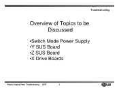
Troubleshooting Overview of Topics to be Discussed •Switch Mode Power Supply •Y SUS Board •Z SUS Board •X Drive Boards Plasma Display Panel Troubleshooting - 2007 2
Troubleshooting Overview of Topics to be Discussed •Switch Mode Power Supply •Y SUS Board •Z SUS Board •X Drive Boards Plasma Display Panel Troubleshooting - 2007 2
Owners Manual
Page 7
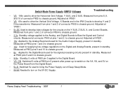
... 1 and 2 of connector P804 to chassis ground. Adjusted at VR221. • 19v Applied to the Analog Board and used for the circuits on the Y SUS, Z SUS, X, and Control Boards. Measured at P800 pin 3 applied to the Digital Board. • VS- Measured at P803 pins 5 and 6 to chassis ground....and 10 to chassis ground. • 6v Applied to the Digital Board used to drive the Vertical Grid Voltage, X Boards and in standby. Plasma Display Panel Troubleshooting - 2007 7 Switch Mode Power Supply (SMPS) Voltages Troubleshooting • VS 196v used to bring the Power Supply out of ...
... 1 and 2 of connector P804 to chassis ground. Adjusted at VR221. • 19v Applied to the Analog Board and used for the circuits on the Y SUS, Z SUS, X, and Control Boards. Measured at P800 pin 3 applied to the Digital Board. • VS- Measured at P803 pins 5 and 6 to chassis ground....and 10 to chassis ground. • 6v Applied to the Digital Board used to drive the Vertical Grid Voltage, X Boards and in standby. Plasma Display Panel Troubleshooting - 2007 7 Switch Mode Power Supply (SMPS) Voltages Troubleshooting • VS 196v used to bring the Power Supply out of ...
Owners Manual
Page 11
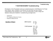
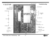
... 115v. -VY -196v. IPM 18v. ER IPM SUS IPM Ramp UP V SET DN V SET UP Plasma Display Panel Troubleshooting - 2007 11 Troubleshooting Y SUSTAIN BOARD Troubleshooting This Section of the circuit and will cover troubleshooting the Y SUS Board for troubleshooting and alignments. • Adjustments • DC Voltage and Waveform Checks • Resistance Measurements Operating... will have a better understanding of the operation of the Presentation will be able to locate voltage and resistance test points needed for the Single Scan Plasma. VS 196v. 5v.
... 115v. -VY -196v. IPM 18v. ER IPM SUS IPM Ramp UP V SET DN V SET UP Plasma Display Panel Troubleshooting - 2007 11 Troubleshooting Y SUSTAIN BOARD Troubleshooting This Section of the circuit and will cover troubleshooting the Y SUS Board for troubleshooting and alignments. • Adjustments • DC Voltage and Waveform Checks • Resistance Measurements Operating... will have a better understanding of the operation of the Presentation will be able to locate voltage and resistance test points needed for the Single Scan Plasma. VS 196v. 5v.
Owners Manual
Page 12
Measured at the VSC test points. • -VY -196v Used to shape the Y Drive waveform by setting the V Scan level. Check VSC Check -VY Plasma Display Panel Troubleshooting - 2007 12 Important Note Troubleshooting • The following voltages and waveforms should be adjusted in the order they are presented. • Always ... Voltmeter make sure the -VY and VSC are the same as the Voltage Label on the upper right side of the PDP. Voltmeter Adjustments to Y SUS • VSC 115v Used to most accurately set the Plasma Display Panel.
Measured at the VSC test points. • -VY -196v Used to shape the Y Drive waveform by setting the V Scan level. Check VSC Check -VY Plasma Display Panel Troubleshooting - 2007 12 Important Note Troubleshooting • The following voltages and waveforms should be adjusted in the order they are presented. • Always ... Voltmeter make sure the -VY and VSC are the same as the Voltage Label on the upper right side of the PDP. Voltmeter Adjustments to Y SUS • VSC 115v Used to most accurately set the Plasma Display Panel.
Owners Manual
Page 22
SMPS Receive 5V,Va, Vs from SMPS Distributes 5v IPM generates Sustain Waveform Generates Vsc, -Vy from 5v VA Vs by transformer. Bottom Left X Board FETs amplify Sustain Waveform Troubleshooting Control Board Logic signals needed to generate drive waveform Transfer Waveform to Y Drive Board Display Panel Plasma Display Panel Troubleshooting - 2007 22 Diagram of Y Sustain Board Y Sustain Board Z SUS Board Distributes 5v VA VS Distributes 5v VA Power Supply Board -
SMPS Receive 5V,Va, Vs from SMPS Distributes 5v IPM generates Sustain Waveform Generates Vsc, -Vy from 5v VA Vs by transformer. Bottom Left X Board FETs amplify Sustain Waveform Troubleshooting Control Board Logic signals needed to generate drive waveform Transfer Waveform to Y Drive Board Display Panel Plasma Display Panel Troubleshooting - 2007 22 Diagram of Y Sustain Board Y Sustain Board Z SUS Board Distributes 5v VA VS Distributes 5v VA Power Supply Board -
Owners Manual
Page 23
ER IPM. SUS IPM. 2. SUS IPM (IC202) 2. IPM (Intelligent Power Module) Troubleshooting SUS_UP ER_UP ER_DN SUS_DN SUS_DN There are two IPMs used in 50PC1DR on the Y Sustain Board. 1. Plasma Display Panel Troubleshooting - 2007 23 Generate Sustain Waveform (square wave) - ER IPM (IC201) Role of IPMs 1. Energy Recovery Function (for saving power) -
ER IPM. SUS IPM. 2. SUS IPM (IC202) 2. IPM (Intelligent Power Module) Troubleshooting SUS_UP ER_UP ER_DN SUS_DN SUS_DN There are two IPMs used in 50PC1DR on the Y Sustain Board. 1. Plasma Display Panel Troubleshooting - 2007 23 Generate Sustain Waveform (square wave) - ER IPM (IC201) Role of IPMs 1. Energy Recovery Function (for saving power) -
Owners Manual
Page 24
GRND ( + ), ER-UP ( - ) 5. 18v ( - ), ER GRND ( + ) 6. 5v ( - ), ER GRND ( + ) Reverse Test : 1. Sus-out ( - ), Vs (+) 3. GND (+), Sus-out ( - ) 2. ER-DN (+), GRND ( - ) 1.4 4. How to ER_lO OPEN in Diode Check Plasma Display Panel Troubleshooting - 2007 24 Troubleshooting Sus-out (+), Vs ( - ) 3. GRND ( - ), ER-UP ( + ) 1.4 5. 18v ( + ), GRND ( - ) 1.9 6. 5v ( + ), GRND ( - ) .9 Note: ER_HIGH ER_LOW, to check IPM (Resistance...
GRND ( + ), ER-UP ( - ) 5. 18v ( - ), ER GRND ( + ) 6. 5v ( - ), ER GRND ( + ) Reverse Test : 1. Sus-out ( - ), Vs (+) 3. GND (+), Sus-out ( - ) 2. ER-DN (+), GRND ( - ) 1.4 4. How to ER_lO OPEN in Diode Check Plasma Display Panel Troubleshooting - 2007 24 Troubleshooting Sus-out (+), Vs ( - ) 3. GRND ( - ), ER-UP ( + ) 1.4 5. 18v ( + ), GRND ( - ) 1.9 6. 5v ( + ), GRND ( - ) .9 Note: ER_HIGH ER_LOW, to check IPM (Resistance...
Owners Manual
Page 27
... Logic signals to Y Drive Boards to sequentially scan the Horizontal Grid floating ground 64v Y SUS output 64v floating ground 18v IPM Measured at R61 Oscilloscope Waveform adjust test point Plasma Display Panel Troubleshooting - 2007 P2 27 P11 to Z SUS Board 5v VA VS Troubleshooting ER_IPM (IC201) P1 VA Ground VS P5 5v Ground...
... Logic signals to Y Drive Boards to sequentially scan the Horizontal Grid floating ground 64v Y SUS output 64v floating ground 18v IPM Measured at R61 Oscilloscope Waveform adjust test point Plasma Display Panel Troubleshooting - 2007 P2 27 P11 to Z SUS Board 5v VA VS Troubleshooting ER_IPM (IC201) P1 VA Ground VS P5 5v Ground...
Owners Manual
Page 29
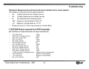
...Floating Ground to Y Drive input measure in Diode Mode Y SUSTAIN Board removed from PDP Assembly (all resistance measurements are approximations) • VS to SUS OUT 1 Meg • SUS OUT to Chassis Ground 1 Meg • SUS_UP(+) SUS_DN(-) 450K • ER_LO to ER10 1 Meg • ER_HIGH to ER10 1 Meg &#...Chassis Ground 10K • ER_DN to Chassis Ground 10K • SUS_UP to Chassis Ground 700K • SUS_DN to Chassis Ground 700K • Y SUS out at B1 to Floating Ground 2 Meg (infinite in Diode Mode) • VSC Test Points Measure in Diode Mode • -VY Test ...
...Floating Ground to Y Drive input measure in Diode Mode Y SUSTAIN Board removed from PDP Assembly (all resistance measurements are approximations) • VS to SUS OUT 1 Meg • SUS OUT to Chassis Ground 1 Meg • SUS_UP(+) SUS_DN(-) 450K • ER_LO to ER10 1 Meg • ER_HIGH to ER10 1 Meg &#...Chassis Ground 10K • ER_DN to Chassis Ground 10K • SUS_UP to Chassis Ground 700K • SUS_DN to Chassis Ground 700K • Y SUS out at B1 to Floating Ground 2 Meg (infinite in Diode Mode) • VSC Test Points Measure in Diode Mode • -VY Test ...
Owners Manual
Page 33
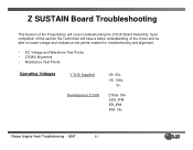
Z Bias 90v SUS_IPM ER_IPM IPM 18v Plasma Display Panel Troubleshooting - 2007 33 Z SUSTAIN Board Troubleshooting This Section of the Presentation will have a better understanding of this section the Technician will cover troubleshooting the Z-SUS Board Assembly. VS 196v. 5v. Upon completion of the circuit and be able to locate voltage and resistance test points needed for troubleshooting and alignment. • DC Voltage and Waveform Test Points • Z BIAS Alignment • Resistance Test Points Operating Voltages Y SUS Supplied Developed on Z SUS VA 60v.
Z Bias 90v SUS_IPM ER_IPM IPM 18v Plasma Display Panel Troubleshooting - 2007 33 Z SUSTAIN Board Troubleshooting This Section of the Presentation will have a better understanding of this section the Technician will cover troubleshooting the Z-SUS Board Assembly. VS 196v. 5v. Upon completion of the circuit and be able to locate voltage and resistance test points needed for troubleshooting and alignment. • DC Voltage and Waveform Test Points • Z BIAS Alignment • Resistance Test Points Operating Voltages Y SUS Supplied Developed on Z SUS VA 60v.
Owners Manual
Page 34
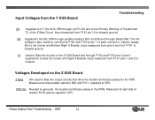
... the Primary Winding of Transformer T2 of each connector. Measured across parallel resistors R25 and R111, adjusted at pin 7 of the Z Bias Circuit. Plasma Display Panel Troubleshooting - 2007 34 Used to supply 60v to the Center and Bottom Right X Boards. The VA voltage is also routed to connectors... P152 and P153 at VR3. Input measured from P151 pins 1 and 2 to chassis Voltages Developed on the Z SUS Board and through P152 and P153 pins 3 and 4 supplies 5v to bias the Center and Right X Boards. Input measured from pins 8 and 9 of...
... the Primary Winding of Transformer T2 of each connector. Measured across parallel resistors R25 and R111, adjusted at pin 7 of the Z Bias Circuit. Plasma Display Panel Troubleshooting - 2007 34 Used to supply 60v to the Center and Bottom Right X Boards. The VA voltage is also routed to connectors... P152 and P153 at VR3. Input measured from P151 pins 1 and 2 to chassis Voltages Developed on the Z SUS Board and through P152 and P153 pins 3 and 4 supplies 5v to bias the Center and Right X Boards. Input measured from pins 8 and 9 of...
Owners Manual
Page 36
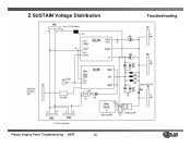
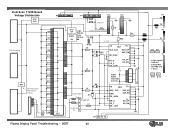
Z SUSTAIN Voltage Distribution From Y SUS Board FL152 Troubleshooting To X Drive Boards Plasma Display Panel Troubleshooting - 2007 36
Z SUSTAIN Voltage Distribution From Y SUS Board FL152 Troubleshooting To X Drive Boards Plasma Display Panel Troubleshooting - 2007 36
Owners Manual
Page 37
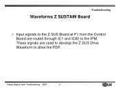
Troubleshooting Waveforms Z SUSTAIN Board • Input signals to the Z SUS Board at P1 from the Control Board are used to develop the Z SUS Drive Waveform to the IPM. Plasma Display Panel Troubleshooting - 2007 37 These signals are routed through IC1 and IC82 to drive the PDP.
Troubleshooting Waveforms Z SUSTAIN Board • Input signals to the Z SUS Board at P1 from the Control Board are used to develop the Z SUS Drive Waveform to the IPM. Plasma Display Panel Troubleshooting - 2007 37 These signals are routed through IC1 and IC82 to drive the PDP.
Owners Manual
Page 38
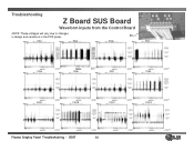
PIN1 PIN2 PIN3 Pin 1 PIN4 PIN5 PIN6 PIN7 PIN8 PIN9 PIN10 PIN11 PIN12 Plasma Display Panel Troubleshooting - 2007 38 Troubleshooting Z Board SUS Board Waveform inputs from the Control Board NOTE: These voltages will vary due to changes in design and variations in the PDP panel.
PIN1 PIN2 PIN3 Pin 1 PIN4 PIN5 PIN6 PIN7 PIN8 PIN9 PIN10 PIN11 PIN12 Plasma Display Panel Troubleshooting - 2007 38 Troubleshooting Z Board SUS Board Waveform inputs from the Control Board NOTE: These voltages will vary due to changes in design and variations in the PDP panel.
Owners Manual
Page 41
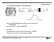
Z SUS IPM (Intelligent Power Module) 95 V Z Vs 95V Vs SUS_UP Troubleshooting SUS_DN ER_UP ER_DN SUS_DN There are Two IPM ( Intelligent Power Module) on the Z sustain board of the 50PC1DR. One is SUS IPM (IC7) , another is ER IPM (IC5) Role of IPM 1.Generate sustain and erase waveform( square wave ) - SUS IPM. 2.Energy recovery function ( for saving power) - ER IPM. Plasma Display Panel Troubleshooting - 2007 41
Z SUS IPM (Intelligent Power Module) 95 V Z Vs 95V Vs SUS_UP Troubleshooting SUS_DN ER_UP ER_DN SUS_DN There are Two IPM ( Intelligent Power Module) on the Z sustain board of the 50PC1DR. One is SUS IPM (IC7) , another is ER IPM (IC5) Role of IPM 1.Generate sustain and erase waveform( square wave ) - SUS IPM. 2.Energy recovery function ( for saving power) - ER IPM. Plasma Display Panel Troubleshooting - 2007 41
Owners Manual
Page 48
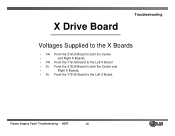
Plasma Display Panel Troubleshooting - 2007 48 X Drive Board Troubleshooting Voltages Supplied to the X Boards • VA From the Z SUS Board to both the Center • and Right X Boards. • VA From the Y SUS Board to the Left X Board • 5v From the Z SUS Board to both the Center and • Right X Boards. • 5v From the Y SUS Board to the Left X Board.
Plasma Display Panel Troubleshooting - 2007 48 X Drive Board Troubleshooting Voltages Supplied to the X Boards • VA From the Z SUS Board to both the Center • and Right X Boards. • VA From the Y SUS Board to the Left X Board • 5v From the Z SUS Board to both the Center and • Right X Boards. • 5v From the Y SUS Board to the Left X Board.
Owners Manual
Page 60
Dual Scan Y SUS Board Voltage Distribution Q16 Q26 Q8 Q7 Q5 VSC Floating Q6 Ground Q12 Q17 Q18 Q19 Q11 B41 Oscilloscope Q15 Waveform Y Drive Q14 Q10 Q13 ... SUS_UP SUS_DN ER_l0 VS_2 ER_ LOW 5v ER_UP ER_DN P7 GND 5V VA Logic signals from the Control BD for IPMs and Y Drive IC10 IC19 Plasma Display Panel Troubleshooting - 2007 60
Dual Scan Y SUS Board Voltage Distribution Q16 Q26 Q8 Q7 Q5 VSC Floating Q6 Ground Q12 Q17 Q18 Q19 Q11 B41 Oscilloscope Q15 Waveform Y Drive Q14 Q10 Q13 ... SUS_UP SUS_DN ER_l0 VS_2 ER_ LOW 5v ER_UP ER_DN P7 GND 5V VA Logic signals from the Control BD for IPMs and Y Drive IC10 IC19 Plasma Display Panel Troubleshooting - 2007 60
Owners Manual
Page 64
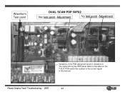
Plasma Display Panel Troubleshooting - 2007 64 Waveform Test point DUAL SCAN PDP 50PX2 Vsc test point, Adjustment -Vy test point, Adjustment Variations in the PCB design will result in variations in this manual. Refer to the label on the Y-SUS PCB match this number to the correct signal in The signal driving the PDP panel.
Plasma Display Panel Troubleshooting - 2007 64 Waveform Test point DUAL SCAN PDP 50PX2 Vsc test point, Adjustment -Vy test point, Adjustment Variations in the PCB design will result in variations in this manual. Refer to the label on the Y-SUS PCB match this number to the correct signal in The signal driving the PDP panel.