Owners Manual
Page 5
Look for correct Amplitude and Timing of the signals. Plasma Display Panel Troubleshooting - 2007 5 If the supplies are noise free. Sometimes "glitches" or "road bumps" will sometimes leak dielectric material and give off a distinct odor. ... short circuits. • Isolate To further isolate the failure check for the proper waveforms with the load, or listen for proper levels. Look for burned parts and check for the proper Duty Cycle of the signals also check for possible overheated components. Be careful of ESD and make a final determination of...
Look for correct Amplitude and Timing of the signals. Plasma Display Panel Troubleshooting - 2007 5 If the supplies are noise free. Sometimes "glitches" or "road bumps" will sometimes leak dielectric material and give off a distinct odor. ... short circuits. • Isolate To further isolate the failure check for the proper waveforms with the load, or listen for proper levels. Look for burned parts and check for the proper Duty Cycle of the signals also check for possible overheated components. Be careful of ESD and make a final determination of...
Owners Manual
Page 14
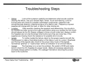
Troubleshooting Single Scan Panel *Waveforms may vary with the probe set to here. Ground VSET DN +VSC Plasma Display Panel Troubleshooting - 2007 14 Normal Waveform RAMP UP Panel Waveform Adjustment 35 micro seconds Scope TP 000 -VY 180 micro seconds VSET UP This test point is the reference for all the following signals referred to 10x1. Readings are taken with different Y_SUSTAIN PCB part #'s.
Troubleshooting Single Scan Panel *Waveforms may vary with the probe set to here. Ground VSET DN +VSC Plasma Display Panel Troubleshooting - 2007 14 Normal Waveform RAMP UP Panel Waveform Adjustment 35 micro seconds Scope TP 000 -VY 180 micro seconds VSET UP This test point is the reference for all the following signals referred to 10x1. Readings are taken with different Y_SUSTAIN PCB part #'s.

Owners Manual
Page 42
Defect name Description of defect Part IPM Fail Dark display P1 Cable connection If the cable was not connected, There is no display Plasma Display Panel Troubleshooting - 2007 42 Troubleshooting Defect display < Dark display > < No display > ▶ Major defect : IPM fail, cable connection.
Defect name Description of defect Part IPM Fail Dark display P1 Cable connection If the cable was not connected, There is no display Plasma Display Panel Troubleshooting - 2007 42 Troubleshooting Defect display < Dark display > < No display > ▶ Major defect : IPM fail, cable connection.
Owners Manual
Page 45
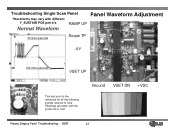
Power : 3.3V/5V Temperature diode Voltage Regulator Flash ROM Voltage Regulator Temperature display diode can be checked. CONTROL Board Troubleshooting ◆. Left picture shows 7 periods which means normal temperature Green = OFF Yellow = ON Weight D15 - 8 D16 - 4 D17 - 2 D18 - 1 TEST Pattern AUTOGEN P1 Connector MCM (Micro Control Module) Plasma Display Panel Troubleshooting - 2007 LG Part Number Label 45 In charge of all signal process and creating ON/OFF order of all FET on DRIVER B/D by receiving 8 bit R, G, B input. ◆.
Power : 3.3V/5V Temperature diode Voltage Regulator Flash ROM Voltage Regulator Temperature display diode can be checked. CONTROL Board Troubleshooting ◆. Left picture shows 7 periods which means normal temperature Green = OFF Yellow = ON Weight D15 - 8 D16 - 4 D17 - 2 D18 - 1 TEST Pattern AUTOGEN P1 Connector MCM (Micro Control Module) Plasma Display Panel Troubleshooting - 2007 LG Part Number Label 45 In charge of all signal process and creating ON/OFF order of all FET on DRIVER B/D by receiving 8 bit R, G, B input. ◆.

Owners Manual
Page 47
... operating voltages). If patterns are not present, Control board is defective LVDS Connector Replace Control Board Reconnect LVDS or Replace Control Board Plasma Display Panel Troubleshooting - 2007 47 < Display Lines > < Partly no display < Connector > Reseat Control Board Connectors Oscilator LVDS poor connection No picture < Oscillator > Remove LVDS Cable and short pins 1 and...
... operating voltages). If patterns are not present, Control board is defective LVDS Connector Replace Control Board Reconnect LVDS or Replace Control Board Plasma Display Panel Troubleshooting - 2007 47 < Display Lines > < Partly no display < Connector > Reseat Control Board Connectors Oscilator LVDS poor connection No picture < Oscillator > Remove LVDS Cable and short pins 1 and...
Owners Manual
Page 49
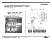
The Control Board supplies the Video Signal to help determine the failed part depending on where the failure is a bar defect on the screen. If there is on the screen, it could be a Control Board problem. Troubleshooting Diagram of Control Board Control Board to X Board Address Signal Flow This will show Signal Flow Distribution to the TCP ICs. MCM Buffer IC Array 16 line 16 line Plasma Display Panel Troubleshooting - 2007 16 output TCP TCP TCP 49
The Control Board supplies the Video Signal to help determine the failed part depending on where the failure is a bar defect on the screen. If there is on the screen, it could be a Control Board problem. Troubleshooting Diagram of Control Board Control Board to X Board Address Signal Flow This will show Signal Flow Distribution to the TCP ICs. MCM Buffer IC Array 16 line 16 line Plasma Display Panel Troubleshooting - 2007 16 output TCP TCP TCP 49

Owners Manual
Page 55
Defect name Description of defect Part Troubleshooting Defect display Vertical abnormal display Poor connection Vertical abnormal display < Poor connection > Attached particle Vertical line ( similar with IC fail ) Check for attached particle or poor connection either one is possible. Plasma Display Panel Troubleshooting - 2007 55 X board ▶ Major defect : Poor connection, Particle inserted.
Defect name Description of defect Part Troubleshooting Defect display Vertical abnormal display Poor connection Vertical abnormal display < Poor connection > Attached particle Vertical line ( similar with IC fail ) Check for attached particle or poor connection either one is possible. Plasma Display Panel Troubleshooting - 2007 55 X board ▶ Major defect : Poor connection, Particle inserted.


