Owners Manual
Page 5
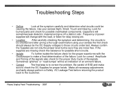
... the product back to correct the problem. Always confirm the Supplies are not only the proper level but be causing the failure. Plasma Display Panel Troubleshooting - 2007 5 Use your senses the first check should always be the DC Supply voltages to make a final ... "glitches" or "road bumps" will be checked and after giving a thorough examination using your senses Sight, Smell, Touch and Hearing. Capacitors will change with the Oscilloscope to those circuits under test. Troubleshooting Steps • Define Look at the symptom carefully and determine what circuits ...
... the product back to correct the problem. Always confirm the Supplies are not only the proper level but be causing the failure. Plasma Display Panel Troubleshooting - 2007 5 Use your senses the first check should always be the DC Supply voltages to make a final ... "glitches" or "road bumps" will be checked and after giving a thorough examination using your senses Sight, Smell, Touch and Hearing. Capacitors will change with the Oscilloscope to those circuits under test. Troubleshooting Steps • Define Look at the symptom carefully and determine what circuits ...
Owners Manual
Page 34
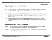
... the Center and Right X Boards. IPM 18v Needed to generate the Sustain and Erase pulses in the IPMs. Measured at pin 7 of the Z Bias Circuit. Plasma Display Panel Troubleshooting - 2007 34 Input Voltages from the Y SUS Board Troubleshooting VS Supplied to IC7 the SUS_IPM through Diode D84. VA Supplied to the... the Center and Bottom Right X Boards. Measured across parallel resistors R25 and R111, adjusted at VR3. Input measured from pins 8 and 9 of resistor R100 (above capacitor C27).
... the Center and Right X Boards. IPM 18v Needed to generate the Sustain and Erase pulses in the IPMs. Measured at pin 7 of the Z Bias Circuit. Plasma Display Panel Troubleshooting - 2007 34 Input Voltages from the Y SUS Board Troubleshooting VS Supplied to IC7 the SUS_IPM through Diode D84. VA Supplied to the... the Center and Bottom Right X Boards. Measured across parallel resistors R25 and R111, adjusted at VR3. Input measured from pins 8 and 9 of resistor R100 (above capacitor C27).