Owners Manual
Page 2
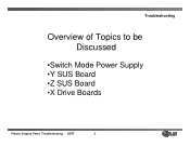
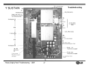
Troubleshooting Overview of Topics to be Discussed •Switch Mode Power Supply •Y SUS Board •Z SUS Board •X Drive Boards Plasma Display Panel Troubleshooting - 2007 2
Troubleshooting Overview of Topics to be Discussed •Switch Mode Power Supply •Y SUS Board •Z SUS Board •X Drive Boards Plasma Display Panel Troubleshooting - 2007 2
Owners Manual
Page 7
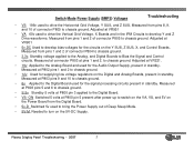
...ON Switched 5 volts at P803 pins 9 and 10 to chassis ground. • 6v Applied to turn on the Digital and Analog Boards, present in standby. Plasma Display Panel Troubleshooting - 2007 7 Measured at P800 pin 5 present after power up to switch on the VA, VS, and 5V on the Power Board from... pins 1 and 2 of Deep Sleep Mode. • 5V-M Needed to the Digital Board used for the circuits on the Y SUS, Z SUS, X, and Control Boards. Measured at P803 pins 5 and 6 to chassis ground. • S 5v Standby 5 volts at P802 pins 1 and 2 to develop bias voltages ...
...ON Switched 5 volts at P803 pins 9 and 10 to chassis ground. • 6v Applied to turn on the Digital and Analog Boards, present in standby. Plasma Display Panel Troubleshooting - 2007 7 Measured at P800 pin 5 present after power up to switch on the VA, VS, and 5V on the Power Board from... pins 1 and 2 of Deep Sleep Mode. • 5V-M Needed to the Digital Board used for the circuits on the Y SUS, Z SUS, X, and Control Boards. Measured at P803 pins 5 and 6 to chassis ground. • S 5v Standby 5 volts at P802 pins 1 and 2 to develop bias voltages ...
Owners Manual
Page 11
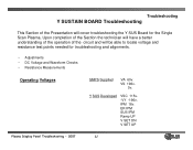
... Ramp UP V SET DN V SET UP Plasma Display Panel Troubleshooting - 2007 11 Y SUS Developed VSC 115v. -VY -196v. IPM 18v. Upon completion of the Section the technician will have a better understanding of the operation of the ...Presentation will be able to locate voltage and resistance test points needed for the Single Scan Plasma. VS 196v. 5v. Troubleshooting Y SUSTAIN BOARD Troubleshooting This Section of the circuit and will cover troubleshooting the Y SUS Board for troubleshooting and alignments. • Adjustments • DC Voltage and Waveform Checks • ...
... Ramp UP V SET DN V SET UP Plasma Display Panel Troubleshooting - 2007 11 Y SUS Developed VSC 115v. -VY -196v. IPM 18v. Upon completion of the Section the technician will have a better understanding of the operation of the ...Presentation will be able to locate voltage and resistance test points needed for the Single Scan Plasma. VS 196v. 5v. Troubleshooting Y SUSTAIN BOARD Troubleshooting This Section of the circuit and will cover troubleshooting the Y SUS Board for troubleshooting and alignments. • Adjustments • DC Voltage and Waveform Checks • ...
Owners Manual
Page 12
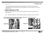
... should be adjusted in the order they are the same as the Voltage Label on the upper right side of the PDP. Voltmeter Adjustments to Y SUS • VSC 115v Used to shape the Y Drive waveform by setting the negative excursion of the V Set Check Y Sustain Board Output Voltage with the Voltmeter... to shape the Y Drive waveform by setting the V Scan level. Measured at the VSC test points. • -VY -196v Used to most accurately set the Plasma Display Panel. Check VSC Check -VY Plasma Display Panel Troubleshooting - 2007 12
... should be adjusted in the order they are the same as the Voltage Label on the upper right side of the PDP. Voltmeter Adjustments to Y SUS • VSC 115v Used to shape the Y Drive waveform by setting the negative excursion of the V Set Check Y Sustain Board Output Voltage with the Voltmeter... to shape the Y Drive waveform by setting the V Scan level. Measured at the VSC test points. • -VY -196v Used to most accurately set the Plasma Display Panel. Check VSC Check -VY Plasma Display Panel Troubleshooting - 2007 12
Owners Manual
Page 22
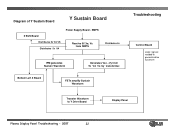
Bottom Left X Board FETs amplify Sustain Waveform Troubleshooting Control Board Logic signals needed to generate drive waveform Transfer Waveform to Y Drive Board Display Panel Plasma Display Panel Troubleshooting - 2007 22 SMPS Receive 5V,Va, Vs from SMPS Distributes 5v IPM generates Sustain Waveform Generates Vsc, -Vy from 5v VA Vs by transformer. Diagram of Y Sustain Board Y Sustain Board Z SUS Board Distributes 5v VA VS Distributes 5v VA Power Supply Board -
Bottom Left X Board FETs amplify Sustain Waveform Troubleshooting Control Board Logic signals needed to generate drive waveform Transfer Waveform to Y Drive Board Display Panel Plasma Display Panel Troubleshooting - 2007 22 SMPS Receive 5V,Va, Vs from SMPS Distributes 5v IPM generates Sustain Waveform Generates Vsc, -Vy from 5v VA Vs by transformer. Diagram of Y Sustain Board Y Sustain Board Z SUS Board Distributes 5v VA VS Distributes 5v VA Power Supply Board -
Owners Manual
Page 23
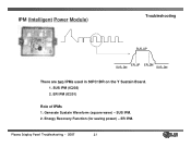
SUS IPM. 2. Energy Recovery Function (for saving power) - IPM (Intelligent Power Module) Troubleshooting SUS_UP ER_UP ER_DN SUS_DN SUS_DN There are two IPMs used in 50PC1DR on the Y Sustain Board. 1. SUS IPM (IC202) 2. ER IPM. Plasma Display Panel Troubleshooting - 2007 23 Generate Sustain Waveform (square wave) - ER IPM (IC201) Role of IPMs 1.
SUS IPM. 2. Energy Recovery Function (for saving power) - IPM (Intelligent Power Module) Troubleshooting SUS_UP ER_UP ER_DN SUS_DN SUS_DN There are two IPMs used in 50PC1DR on the Y Sustain Board. 1. SUS IPM (IC202) 2. ER IPM. Plasma Display Panel Troubleshooting - 2007 23 Generate Sustain Waveform (square wave) - ER IPM (IC201) Role of IPMs 1.
Owners Manual
Page 24
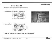
...-UP ( + ) 1.4 5. 18v ( + ), GRND ( - ) 1.9 6. 5v ( + ), GRND ( - ) .9 Note: ER_HIGH ER_LOW, to check IPM (Resistance 'Diode Check', board removed from set) Forward Test : 1. Sus-out ( - ), Vs (+) 3. GRND ( + ), ER-UP ( - ) 5. 18v ( - ), ER GRND ( + ) 6. 5v ( - ), ER GRND ( + ) Reverse Test : 1. GND (+), Sus-out ( - ) 2. How to ER_lO OPEN in Diode Check Plasma Display Panel Troubleshooting - 2007 24 Troubleshooting
...-UP ( + ) 1.4 5. 18v ( + ), GRND ( - ) 1.9 6. 5v ( + ), GRND ( - ) .9 Note: ER_HIGH ER_LOW, to check IPM (Resistance 'Diode Check', board removed from set) Forward Test : 1. Sus-out ( - ), Vs (+) 3. GRND ( + ), ER-UP ( - ) 5. 18v ( - ), ER GRND ( + ) 6. 5v ( - ), ER GRND ( + ) Reverse Test : 1. GND (+), Sus-out ( - ) 2. How to ER_lO OPEN in Diode Check Plasma Display Panel Troubleshooting - 2007 24 Troubleshooting
Owners Manual
Page 27
... Logic signals to Y Drive Boards to sequentially scan the Horizontal Grid floating ground 64v Y SUS output 64v floating ground 18v IPM Measured at R61 Oscilloscope Waveform adjust test point Plasma Display Panel Troubleshooting - 2007 P2 27 P11 to Z SUS Board 5v VA VS Troubleshooting ER_IPM (IC201) P1 VA Ground VS P5 5v Ground...
... Logic signals to Y Drive Boards to sequentially scan the Horizontal Grid floating ground 64v Y SUS output 64v floating ground 18v IPM Measured at R61 Oscilloscope Waveform adjust test point Plasma Display Panel Troubleshooting - 2007 P2 27 P11 to Z SUS Board 5v VA VS Troubleshooting ER_IPM (IC201) P1 VA Ground VS P5 5v Ground...
Owners Manual
Page 29
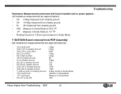
...Floating Ground to Y Drive input measure in Diode Mode Y SUSTAIN Board removed from PDP Assembly (all resistance measurements are approximations) • VS to SUS OUT 1 Meg • SUS OUT to Chassis Ground 1 Meg • SUS_UP(+) SUS_DN(-) 450K • ER_LO to ER10 1 Meg • ER_HIGH to ER10 1 Meg &#...Chassis Ground 10K • ER_DN to Chassis Ground 10K • SUS_UP to Chassis Ground 700K • SUS_DN to Chassis Ground 700K • Y SUS out at B1 to Floating Ground 2 Meg (infinite in Diode Mode) • VSC Test Points Measure in Diode Mode • -VY Test ...
...Floating Ground to Y Drive input measure in Diode Mode Y SUSTAIN Board removed from PDP Assembly (all resistance measurements are approximations) • VS to SUS OUT 1 Meg • SUS OUT to Chassis Ground 1 Meg • SUS_UP(+) SUS_DN(-) 450K • ER_LO to ER10 1 Meg • ER_HIGH to ER10 1 Meg &#...Chassis Ground 10K • ER_DN to Chassis Ground 10K • SUS_UP to Chassis Ground 700K • SUS_DN to Chassis Ground 700K • Y SUS out at B1 to Floating Ground 2 Meg (infinite in Diode Mode) • VSC Test Points Measure in Diode Mode • -VY Test ...
Owners Manual
Page 33
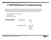
Z Bias 90v SUS_IPM ER_IPM IPM 18v Plasma Display Panel Troubleshooting - 2007 33 Z SUSTAIN Board Troubleshooting This Section of the circuit and be able to locate voltage and resistance test points needed for troubleshooting and alignment. • DC Voltage and Waveform Test Points • Z BIAS Alignment • Resistance Test Points Operating Voltages Y SUS Supplied Developed on Z SUS VA 60v. VS 196v. 5v. Upon completion of this section the Technician will have a better understanding of the Presentation will cover troubleshooting the Z-SUS Board Assembly.
Z Bias 90v SUS_IPM ER_IPM IPM 18v Plasma Display Panel Troubleshooting - 2007 33 Z SUSTAIN Board Troubleshooting This Section of the circuit and be able to locate voltage and resistance test points needed for troubleshooting and alignment. • DC Voltage and Waveform Test Points • Z BIAS Alignment • Resistance Test Points Operating Voltages Y SUS Supplied Developed on Z SUS VA 60v. VS 196v. 5v. Upon completion of this section the Technician will have a better understanding of the Presentation will cover troubleshooting the Z-SUS Board Assembly.
Owners Manual
Page 34
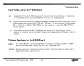
... Diode D84. IPM 18v Needed to generate the Sustain and Erase pulses in the IPMs. Measured at pin 7 of resistor R100 (above capacitor C27). Plasma Display Panel Troubleshooting - 2007 34 The VA voltage is also routed to connectors P152 and P153 at right side of each connector. Measured across parallel... for the PDP. Input measured from pins 8 and 9 of the Z Bias Circuit. Input measured from P151 pins 1 and 2 to chassis Voltages Developed on the Z SUS Board and through P152 and P153 pins 3 and 4 supplies 5v to bias the Center and Right X Boards. Input Voltages from the...
... Diode D84. IPM 18v Needed to generate the Sustain and Erase pulses in the IPMs. Measured at pin 7 of resistor R100 (above capacitor C27). Plasma Display Panel Troubleshooting - 2007 34 The VA voltage is also routed to connectors P152 and P153 at right side of each connector. Measured across parallel... for the PDP. Input measured from pins 8 and 9 of the Z Bias Circuit. Input measured from P151 pins 1 and 2 to chassis Voltages Developed on the Z SUS Board and through P152 and P153 pins 3 and 4 supplies 5v to bias the Center and Right X Boards. Input Voltages from the...
Owners Manual
Page 36
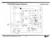
Z SUSTAIN Voltage Distribution From Y SUS Board FL152 Troubleshooting To X Drive Boards Plasma Display Panel Troubleshooting - 2007 36
Z SUSTAIN Voltage Distribution From Y SUS Board FL152 Troubleshooting To X Drive Boards Plasma Display Panel Troubleshooting - 2007 36
Owners Manual
Page 37
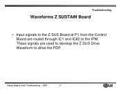
Plasma Display Panel Troubleshooting - 2007 37 Troubleshooting Waveforms Z SUSTAIN Board • Input signals to the Z SUS Board at P1 from the Control Board are used to develop the Z SUS Drive Waveform to the IPM. These signals are routed through IC1 and IC82 to drive the PDP.
Plasma Display Panel Troubleshooting - 2007 37 Troubleshooting Waveforms Z SUSTAIN Board • Input signals to the Z SUS Board at P1 from the Control Board are used to develop the Z SUS Drive Waveform to the IPM. These signals are routed through IC1 and IC82 to drive the PDP.
Owners Manual
Page 38
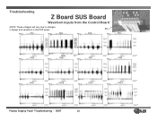
PIN1 PIN2 PIN3 Pin 1 PIN4 PIN5 PIN6 PIN7 PIN8 PIN9 PIN10 PIN11 PIN12 Plasma Display Panel Troubleshooting - 2007 38 Troubleshooting Z Board SUS Board Waveform inputs from the Control Board NOTE: These voltages will vary due to changes in design and variations in the PDP panel.
PIN1 PIN2 PIN3 Pin 1 PIN4 PIN5 PIN6 PIN7 PIN8 PIN9 PIN10 PIN11 PIN12 Plasma Display Panel Troubleshooting - 2007 38 Troubleshooting Z Board SUS Board Waveform inputs from the Control Board NOTE: These voltages will vary due to changes in design and variations in the PDP panel.
Owners Manual
Page 41
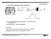
SUS IPM. 2.Energy recovery function ( for saving power) - Plasma Display Panel Troubleshooting - 2007 41 ER IPM. Z SUS IPM (Intelligent Power Module) 95 V Z Vs 95V Vs SUS_UP Troubleshooting SUS_DN ER_UP ER_DN SUS_DN There are Two IPM ( Intelligent Power Module) on the Z sustain board of the 50PC1DR. One is SUS IPM (IC7) , another is ER IPM (IC5) Role of IPM 1.Generate sustain and erase waveform( square wave ) -
SUS IPM. 2.Energy recovery function ( for saving power) - Plasma Display Panel Troubleshooting - 2007 41 ER IPM. Z SUS IPM (Intelligent Power Module) 95 V Z Vs 95V Vs SUS_UP Troubleshooting SUS_DN ER_UP ER_DN SUS_DN There are Two IPM ( Intelligent Power Module) on the Z sustain board of the 50PC1DR. One is SUS IPM (IC7) , another is ER IPM (IC5) Role of IPM 1.Generate sustain and erase waveform( square wave ) -
Owners Manual
Page 48
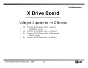
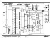
Plasma Display Panel Troubleshooting - 2007 48 X Drive Board Troubleshooting Voltages Supplied to the X Boards • VA From the Z SUS Board to both the Center • and Right X Boards. • VA From the Y SUS Board to the Left X Board • 5v From the Z SUS Board to both the Center and • Right X Boards. • 5v From the Y SUS Board to the Left X Board.
Plasma Display Panel Troubleshooting - 2007 48 X Drive Board Troubleshooting Voltages Supplied to the X Boards • VA From the Z SUS Board to both the Center • and Right X Boards. • VA From the Y SUS Board to the Left X Board • 5v From the Z SUS Board to both the Center and • Right X Boards. • 5v From the Y SUS Board to the Left X Board.
Owners Manual
Page 60
... ER_ LOW 5v ER_UP ER_DN P7 GND 5V VA Logic signals from the Control BD for IPMs and Y Drive IC10 IC19 Plasma Display Panel Troubleshooting - 2007 60 Dual Scan Y SUS Board Voltage Distribution Q16 Q26 Q8 Q7 Q5 VSC Floating Q6 Ground Q12 Q17 Q18 Q19 Q11 B41 Oscilloscope Q15 Waveform Y Drive...
... ER_ LOW 5v ER_UP ER_DN P7 GND 5V VA Logic signals from the Control BD for IPMs and Y Drive IC10 IC19 Plasma Display Panel Troubleshooting - 2007 60 Dual Scan Y SUS Board Voltage Distribution Q16 Q26 Q8 Q7 Q5 VSC Floating Q6 Ground Q12 Q17 Q18 Q19 Q11 B41 Oscilloscope Q15 Waveform Y Drive...
Owners Manual
Page 64
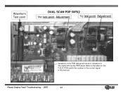
Waveform Test point DUAL SCAN PDP 50PX2 Vsc test point, Adjustment -Vy test point, Adjustment Variations in the PCB design will result in variations in this manual. Plasma Display Panel Troubleshooting - 2007 64 Refer to the label on the Y-SUS PCB match this number to the correct signal in The signal driving the PDP panel.
Waveform Test point DUAL SCAN PDP 50PX2 Vsc test point, Adjustment -Vy test point, Adjustment Variations in the PCB design will result in variations in this manual. Plasma Display Panel Troubleshooting - 2007 64 Refer to the label on the Y-SUS PCB match this number to the correct signal in The signal driving the PDP panel.