Owners Manual
Page 2
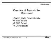
Troubleshooting Overview of Topics to be Discussed •Switch Mode Power Supply •Y SUS Board •Z SUS Board •X Drive Boards Plasma Display Panel Troubleshooting - 2007 2
Troubleshooting Overview of Topics to be Discussed •Switch Mode Power Supply •Y SUS Board •Z SUS Board •X Drive Boards Plasma Display Panel Troubleshooting - 2007 2

Owners Manual
Page 4
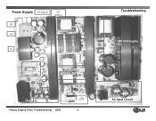
... Troubleshooting This Section of the PDP for the correct voltage levels for the Single Scan Plasma. Upon completion of the section the technician will have a better understanding of the operation of the Power Supply circuit and will be able to locate voltage and test points needed for troubleshooting and alignments. •..., VS, and 5V DC • Always refer to the sticker located in the upper right side of the Presentation will cover troubleshooting the Switch Mode Power Supply for the DC 5v, VA, VS, V SET UP, -VY, VSC, and Z Bias as they will vary from Panel to Panel. V SET_UP -VY ...
... Troubleshooting This Section of the PDP for the correct voltage levels for the Single Scan Plasma. Upon completion of the section the technician will have a better understanding of the operation of the Power Supply circuit and will be able to locate voltage and test points needed for troubleshooting and alignments. •..., VS, and 5V DC • Always refer to the sticker located in the upper right side of the Presentation will cover troubleshooting the Switch Mode Power Supply for the DC 5v, VA, VS, V SET UP, -VY, VSC, and Z Bias as they will vary from Panel to Panel. V SET_UP -VY ...
Owners Manual
Page 5
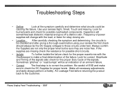
...to check the DC Supplies for proper levels. Frequency of the failure. Be careful of ESD and make a final determination of power supplies will change with the Oscilloscope to make sure to correct the problem. Make all necessary adjustments and lastly always perform a...proper waveforms with the load, or listen for possible overheated components. Capacitors will be causing the failure. If the supplies are noise free. Plasma Display Panel Troubleshooting - 2007 5 Sometimes "glitches" or "road bumps" will sometimes leak dielectric material and give off a distinct odor. ...
...to check the DC Supplies for proper levels. Frequency of the failure. Be careful of ESD and make a final determination of power supplies will change with the Oscilloscope to make sure to correct the problem. Make all necessary adjustments and lastly always perform a...proper waveforms with the load, or listen for possible overheated components. Capacitors will be causing the failure. If the supplies are noise free. Plasma Display Panel Troubleshooting - 2007 5 Sometimes "glitches" or "road bumps" will sometimes leak dielectric material and give off a distinct odor. ...

Owners Manual
Page 6
Plasma Display Panel Troubleshooting - 2007 6 Guide Plus not programmed or Cable Card not installed and set is ...to turn on the SMPS. • Digital Board sends RL-ON to P800 Pin 2 to cause Controller IC U701 on the Power Board to turn on the Relay Drive Transistors Q701 and Q702 closing the Relays RL101 and RL102 turning on the 3.3V, 5V,... turn on the VA, and VS Supplies • 5V-M Sent from the Digital Board to the Power Board to turn on 5V-DC. • 5V-D is powered off . Power Sequence • AC Cord Plugged in full operation. SMPS outputting all of DS Mode as needed for...
Plasma Display Panel Troubleshooting - 2007 6 Guide Plus not programmed or Cable Card not installed and set is ...to turn on the SMPS. • Digital Board sends RL-ON to P800 Pin 2 to cause Controller IC U701 on the Power Board to turn on the Relay Drive Transistors Q701 and Q702 closing the Relays RL101 and RL102 turning on the 3.3V, 5V,... turn on the VA, and VS Supplies • 5V-M Sent from the Digital Board to the Power Board to turn on 5V-DC. • 5V-D is powered off . Power Sequence • AC Cord Plugged in full operation. SMPS outputting all of DS Mode as needed for...
Owners Manual
Page 7
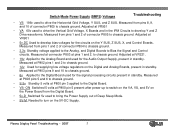
...to Bias the Signal and Control circuits. Adjusted at VR951 • VA 60v used for the signal processing circuits present in standby. Plasma Display Panel Troubleshooting - 2007 7 Adjusted at VR221. • 19v Applied to the Analog Board and used to drive the Vertical... ground. • 3.3v. Measured from the Digital Board. • 5v-D Switched 5v used for the Audio Output Supply, present in standby. Switch Mode Power Supply (SMPS) Voltages Troubleshooting • VS 196v used to chassis ground. • S 5v Standby 5 volts at pins 1 and 2. Measured at P803 ...
...to Bias the Signal and Control circuits. Adjusted at VR951 • VA 60v used for the signal processing circuits present in standby. Plasma Display Panel Troubleshooting - 2007 7 Adjusted at VR221. • 19v Applied to the Analog Board and used to drive the Vertical... ground. • 3.3v. Measured from the Digital Board. • 5v-D Switched 5v used for the Audio Output Supply, present in standby. Switch Mode Power Supply (SMPS) Voltages Troubleshooting • VS 196v used to chassis ground. • S 5v Standby 5 volts at pins 1 and 2. Measured at P803 ...
Owners Manual
Page 8
Power Supply VS Adjust VA Adjust VS VA Source VA 5v VS Source Control IC 3.3v Adjust 19v Audio Supply 12V,6V, 5V and 3.3V Source Standby Circuit P802 P803 P800 Plasma Display Panel Troubleshooting - 2007 8 Troubleshooting 380 Volt Supply AC Input Circuit
Power Supply VS Adjust VA Adjust VS VA Source VA 5v VS Source Control IC 3.3v Adjust 19v Audio Supply 12V,6V, 5V and 3.3V Source Standby Circuit P802 P803 P800 Plasma Display Panel Troubleshooting - 2007 8 Troubleshooting 380 Volt Supply AC Input Circuit
Owners Manual
Page 9
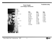
Power Supply Low Voltage Connectors Troubleshooting P800 PIN1 P803 PIN 1 P802 PIN 1 P800 1) AC-D 2) RL-ON 3) S-5V 4) GND 5) VS-ON 6) 5V-D 7) M5V-ON 8) S-5V 9) GND 10) NC 11) 6V 12) N.C 13) 3.3ON P803 1) 3.3V 2) 3.3V 3) GND 4) GND 5) 6V 6) 6V 7) GND 8) GND 9) 12V 10) 12V 11) GND 12) GND P802 1) 19V 2) 19V 3) GND 4) GND 5) 6V 6) GND 7) 3.3V 8) GND 9) 12V 10) GND Plasma Display Panel Troubleshooting - 2007 9
Power Supply Low Voltage Connectors Troubleshooting P800 PIN1 P803 PIN 1 P802 PIN 1 P800 1) AC-D 2) RL-ON 3) S-5V 4) GND 5) VS-ON 6) 5V-D 7) M5V-ON 8) S-5V 9) GND 10) NC 11) 6V 12) N.C 13) 3.3ON P803 1) 3.3V 2) 3.3V 3) GND 4) GND 5) 6V 6) 6V 7) GND 8) GND 9) 12V 10) 12V 11) GND 12) GND P802 1) 19V 2) 19V 3) GND 4) GND 5) 6V 6) GND 7) 3.3V 8) GND 9) 12V 10) GND Plasma Display Panel Troubleshooting - 2007 9
Owners Manual
Page 10
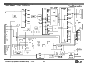
... Q151 Standby Regulator U501 S-5V U601 PCs Control S-5V IC 28 U701 24 20 19 D502 R745 R747 Q702 Q701 D703 D704 Low Voltage Standby Power Supply T501 HS1 D101 D102 AC Relay RL101 AC Relay RL102 120VAC D506 D501 TH01 TH02 Troubleshooting D951 VS D952 D953 D271 6V D261 Q252... D251 D202 VA 5V-M Q281 5V HS6 U261 Q223 D221 3.3v AC Input F101 AC INPUT Circuit Plasma Display Panel Troubleshooting - 2007 10 Power Supply Voltage Distribution HS2 Q607 Q801 PC901 HS3 U801 HS4 T801 R606 R607 Q606 Q601 U851 T902 Q854 R963 P802 19V 3.3V 12V...
... Q151 Standby Regulator U501 S-5V U601 PCs Control S-5V IC 28 U701 24 20 19 D502 R745 R747 Q702 Q701 D703 D704 Low Voltage Standby Power Supply T501 HS1 D101 D102 AC Relay RL101 AC Relay RL102 120VAC D506 D501 TH01 TH02 Troubleshooting D951 VS D952 D953 D271 6V D261 Q252... D251 D202 VA 5V-M Q281 5V HS6 U261 Q223 D221 3.3v AC Input F101 AC INPUT Circuit Plasma Display Panel Troubleshooting - 2007 10 Power Supply Voltage Distribution HS2 Q607 Q801 PC901 HS3 U801 HS4 T801 R606 R607 Q606 Q601 U851 T902 Q854 R963 P802 19V 3.3V 12V...
Owners Manual
Page 22
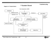
SMPS Receive 5V,Va, Vs from SMPS Distributes 5v IPM generates Sustain Waveform Generates Vsc, -Vy from 5v VA Vs by transformer. Bottom Left X Board FETs amplify Sustain Waveform Troubleshooting Control Board Logic signals needed to generate drive waveform Transfer Waveform to Y Drive Board Display Panel Plasma Display Panel Troubleshooting - 2007 22 Diagram of Y Sustain Board Y Sustain Board Z SUS Board Distributes 5v VA VS Distributes 5v VA Power Supply Board -
SMPS Receive 5V,Va, Vs from SMPS Distributes 5v IPM generates Sustain Waveform Generates Vsc, -Vy from 5v VA Vs by transformer. Bottom Left X Board FETs amplify Sustain Waveform Troubleshooting Control Board Logic signals needed to generate drive waveform Transfer Waveform to Y Drive Board Display Panel Plasma Display Panel Troubleshooting - 2007 22 Diagram of Y Sustain Board Y Sustain Board Z SUS Board Distributes 5v VA VS Distributes 5v VA Power Supply Board -
Owners Manual
Page 23
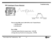
SUS IPM (IC202) 2. Energy Recovery Function (for saving power) - IPM (Intelligent Power Module) Troubleshooting SUS_UP ER_UP ER_DN SUS_DN SUS_DN There are two IPMs used in 50PC1DR on the Y Sustain Board. 1. SUS IPM. 2. ER IPM (IC201) Role of IPMs 1. Generate Sustain Waveform (square wave) - ER IPM. Plasma Display Panel Troubleshooting - 2007 23
SUS IPM (IC202) 2. Energy Recovery Function (for saving power) - IPM (Intelligent Power Module) Troubleshooting SUS_UP ER_UP ER_DN SUS_DN SUS_DN There are two IPMs used in 50PC1DR on the Y Sustain Board. 1. SUS IPM. 2. ER IPM (IC201) Role of IPMs 1. Generate Sustain Waveform (square wave) - ER IPM. Plasma Display Panel Troubleshooting - 2007 23
Owners Manual
Page 29
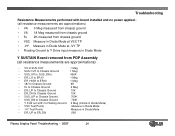
Troubleshooting Resistance Measurements performed with board installed and no power applied (all resistance measurements are approximations) • VA 3 Meg measured from chassis ground • VS 18 Meg measured from chassis ground • 5v 2K measured ... (infinite in Diode Mode) • VSC Test Points Measure in Diode Mode • -VY Test Points Measure in Diode Mode • ER_UP to ER_DN 20K Plasma Display Panel Troubleshooting - 2007 29
Troubleshooting Resistance Measurements performed with board installed and no power applied (all resistance measurements are approximations) • VA 3 Meg measured from chassis ground • VS 18 Meg measured from chassis ground • 5v 2K measured ... (infinite in Diode Mode) • VSC Test Points Measure in Diode Mode • -VY Test Points Measure in Diode Mode • ER_UP to ER_DN 20K Plasma Display Panel Troubleshooting - 2007 29
Owners Manual
Page 41
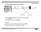
Plasma Display Panel Troubleshooting - 2007 41 ER IPM. SUS IPM. 2.Energy recovery function ( for saving power) - Z SUS IPM (Intelligent Power Module) 95 V Z Vs 95V Vs SUS_UP Troubleshooting SUS_DN ER_UP ER_DN SUS_DN There are Two IPM ( Intelligent Power Module) on the Z sustain board of the 50PC1DR. One is SUS IPM (IC7) , another is ER IPM (IC5) Role of IPM 1.Generate sustain and erase waveform( square wave ) -
Plasma Display Panel Troubleshooting - 2007 41 ER IPM. SUS IPM. 2.Energy recovery function ( for saving power) - Z SUS IPM (Intelligent Power Module) 95 V Z Vs 95V Vs SUS_UP Troubleshooting SUS_DN ER_UP ER_DN SUS_DN There are Two IPM ( Intelligent Power Module) on the Z sustain board of the 50PC1DR. One is SUS IPM (IC7) , another is ER IPM (IC5) Role of IPM 1.Generate sustain and erase waveform( square wave ) -
Owners Manual
Page 45
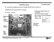
CONTROL Board Troubleshooting ◆. In charge of all signal process and creating ON/OFF order of all FET on DRIVER B/D by receiving 8 bit R, G, B input. ◆. Left picture shows 7 periods which means normal temperature Green = OFF Yellow = ON Weight D15 - 8 D16 - 4 D17 - 2 D18 - 1 TEST Pattern AUTOGEN P1 Connector MCM (Micro Control Module) Plasma Display Panel Troubleshooting - 2007 LG Part Number Label 45 Power : 3.3V/5V Temperature diode Voltage Regulator Flash ROM Voltage Regulator Temperature display diode can be checked.
CONTROL Board Troubleshooting ◆. In charge of all signal process and creating ON/OFF order of all FET on DRIVER B/D by receiving 8 bit R, G, B input. ◆. Left picture shows 7 periods which means normal temperature Green = OFF Yellow = ON Weight D15 - 8 D16 - 4 D17 - 2 D18 - 1 TEST Pattern AUTOGEN P1 Connector MCM (Micro Control Module) Plasma Display Panel Troubleshooting - 2007 LG Part Number Label 45 Power : 3.3V/5V Temperature diode Voltage Regulator Flash ROM Voltage Regulator Temperature display diode can be checked.
Owners Manual
Page 82
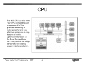
Plasma Display Panel Troubleshooting - 2007 82 Optimized interfaces to make powerful and cost effective system-on-a-chip designs a reality. CPU The 405 CPU core is 100% PowerPC compatible and possesses all of the qualities necessary to the Core Connect bus structure provide for a high bandwidth, low latency system interface solution.
Plasma Display Panel Troubleshooting - 2007 82 Optimized interfaces to make powerful and cost effective system-on-a-chip designs a reality. CPU The 405 CPU core is 100% PowerPC compatible and possesses all of the qualities necessary to the Core Connect bus structure provide for a high bandwidth, low latency system interface solution.
Owners Manual
Page 93
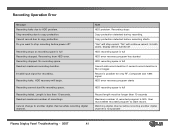
... record due to HDD problem. Reached maximum recording duration. HDD recovery will continue record. Recording failed. Length is not possible Plasma Display Panel Troubleshooting - 2007 93 Copy protection detected before power off HDD recording space is full HDD error recovery program has started HDD recording space is full Cannot add record duration...
... record due to HDD problem. Reached maximum recording duration. HDD recovery will continue record. Recording failed. Length is not possible Plasma Display Panel Troubleshooting - 2007 93 Copy protection detected before power off HDD recording space is full HDD error recovery program has started HDD recording space is full Cannot add record duration...

Owners Manual
Page 98
TROUBLE SHOOTING Eliminate the HDD • If you suspect the HDD is causing a video or audio problem you can simply unplug it • You MUST unplug the TV before disconnecting or reconnecting the HDD • During initial power up the TV will detect whether or not the HDD is there and will route the audio and video as needed Plasma Display Panel Troubleshooting - 2007 98
TROUBLE SHOOTING Eliminate the HDD • If you suspect the HDD is causing a video or audio problem you can simply unplug it • You MUST unplug the TV before disconnecting or reconnecting the HDD • During initial power up the TV will detect whether or not the HDD is there and will route the audio and video as needed Plasma Display Panel Troubleshooting - 2007 98
Owners Manual
Page 99
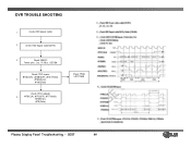
... • Check LED150 blinking • Check PCI bus 4. Check CPLD(IC900) inputs: 5. Check CPLD(IC900) outputs: Plasma Display Panel Troubleshooting - 2007 99 DVR TROUBLE SHOOTING 1 Check HDD power cable 2 Check HDD Signal Cable(SATA) 3 Check SiI3512 Power pins, Osc, PCI Bus, LED150 Check CPLD inputs #140(CLK), #138(SOP), #137(Valid), 4 #139(Error...
... • Check LED150 blinking • Check PCI bus 4. Check CPLD(IC900) inputs: 5. Check CPLD(IC900) outputs: Plasma Display Panel Troubleshooting - 2007 99 DVR TROUBLE SHOOTING 1 Check HDD power cable 2 Check HDD Signal Cable(SATA) 3 Check SiI3512 Power pins, Osc, PCI Bus, LED150 Check CPLD inputs #140(CLK), #138(SOP), #137(Valid), 4 #139(Error...


