
User Manual
Page 6
... coming from the TV or hear strange sounds, unplug the power cord contact an authorized service center. 25 Do not press strongly upon the panel with chemicals such as tiny red, green, or blue spots. Do not press against it can occur. Do not install in the vicinity of mercury. Disposal of time. Do not clean with a hand or...
... coming from the TV or hear strange sounds, unplug the power cord contact an authorized service center. 25 Do not press strongly upon the panel with chemicals such as tiny red, green, or blue spots. Do not press against it can occur. Do not install in the vicinity of mercury. Disposal of time. Do not clean with a hand or...
User Manual
Page 7
... Balance 67 TV Speakers On/Off Setup 68 Audio Reset 69 Stereo/SAP Broadcast Setup 70 Audio Language 71 On-Screen Menus Language Selection 72 Caption Mode - Black (Darkness) Level 58 Advanced Control - Preset 54 - Caption Option 75 TIME SETTING Clock Setting - Analog Broadcasting System Captions 73 - Auto Scan (Auto Tuning 38 - WARNING / CAUTION 1 SAFETY INSTRUCTIONS 2 FEATURES OF THIS TV 7 PREPARATION Accessories 8 Front Panel Information 9 Back Panel Information 10 Stand Instruction 12 VESA Wall Mounting 14 Cable Management 15...
... Balance 67 TV Speakers On/Off Setup 68 Audio Reset 69 Stereo/SAP Broadcast Setup 70 Audio Language 71 On-Screen Menus Language Selection 72 Caption Mode - Black (Darkness) Level 58 Advanced Control - Preset 54 - Caption Option 75 TIME SETTING Clock Setting - Analog Broadcasting System Captions 73 - Auto Scan (Auto Tuning 38 - WARNING / CAUTION 1 SAFETY INSTRUCTIONS 2 FEATURES OF THIS TV 7 PREPARATION Accessories 8 Front Panel Information 9 Back Panel Information 10 Stand Instruction 12 VESA Wall Mounting 14 Cable Management 15...

User Manual
Page 22
... to the COMPONENT IN AUDIO jacks on the TV. Component Connection 1. How to use ■ Turn on the digital set-top box. (Refer to the owner's manual for the digital set -top box to connect 1 Connect the video outputs (Y, PB, PR) of the digital set -top box.) ■ Select Component input source using the INPUT button on the remote control. 1 2 GAME CONTROL AV IN 1 VIDEO AUDIO L(MONO) R 2 VIDEO L R AUDIO 1 COMPONENT IN /DVI IN SPEAKER OUT REMOT (8 ) CONTROL Supported Resolutions Signal Component 480i Yes 480p Yes 720p Yes 1080i Yes 1080p Yes HDMI No...
... to the COMPONENT IN AUDIO jacks on the TV. Component Connection 1. How to use ■ Turn on the digital set-top box. (Refer to the owner's manual for the digital set -top box to connect 1 Connect the video outputs (Y, PB, PR) of the digital set -top box.) ■ Select Component input source using the INPUT button on the remote control. 1 2 GAME CONTROL AV IN 1 VIDEO AUDIO L(MONO) R 2 VIDEO L R AUDIO 1 COMPONENT IN /DVI IN SPEAKER OUT REMOT (8 ) CONTROL Supported Resolutions Signal Component 480i Yes 480p Yes 720p Yes 1080i Yes 1080p Yes HDMI No...
User Manual
Page 23
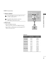
... owner's manual for the digital set -top box to connect 1 Connect the digital set -top box.) ■ Select HDMI1 or HDMI2 input source with using the INPUT button on the TV. 2 No separate audio connection is necessary. How to HDMI /DVI IN 1 or HDMI 2 jack on the remote control. HDMI supports both audio and video. 2. AV IN 1 VIDEO AUDIO RESET UPDATE RGB IN (PC) L(MONO) R 2 L R EO AUDIO 1 MPONENT IN AUDIO IN (RGB/DVI) /DVI IN RS-232C IN (SERVICE ONLY) SPEAKER OUT REMOTE (8 ) CONTROL OUT 1 HDMI OUTPUT HDMI...
... owner's manual for the digital set -top box to connect 1 Connect the digital set -top box.) ■ Select HDMI1 or HDMI2 input source with using the INPUT button on the TV. 2 No separate audio connection is necessary. How to HDMI /DVI IN 1 or HDMI 2 jack on the remote control. HDMI supports both audio and video. 2. AV IN 1 VIDEO AUDIO RESET UPDATE RGB IN (PC) L(MONO) R 2 L R EO AUDIO 1 MPONENT IN AUDIO IN (RGB/DVI) /DVI IN RS-232C IN (SERVICE ONLY) SPEAKER OUT REMOTE (8 ) CONTROL OUT 1 HDMI OUTPUT HDMI...

User Manual
Page 24
EXTERNAL EQUIPMENT SETUP EXTERNAL EQUIPMENT SETUP DVI to HDMI cable or adapter is necessary. How to use ■ Turn on the digital set-top box. (Refer to the owner's manual for this connection. NOTE G A DVI to HDMI Connection 1. DVI doesn't support audio, so a separate audio connection is required for the digital set -top box to the HDMI/DVI IN 1 jack on the TV. 2 Connect the audio output of the digital set -top box.) ■ Select the HDMI1 input source on the TV using the INPUT button on...
EXTERNAL EQUIPMENT SETUP EXTERNAL EQUIPMENT SETUP DVI to HDMI cable or adapter is necessary. How to use ■ Turn on the digital set-top box. (Refer to the owner's manual for this connection. NOTE G A DVI to HDMI Connection 1. DVI doesn't support audio, so a separate audio connection is required for the digital set -top box to the HDMI/DVI IN 1 jack on the TV. 2 Connect the audio output of the digital set -top box.) ■ Select the HDMI1 input source on the TV using the INPUT button on...

User Manual
Page 40
... a password if parental control has been activated (LOCK Menu). MENU ■ The TV will be updated during TV broadcasting hours. Use the password you set up in the LOCK Menu to allow a channel search. ■ When setting the Auto tuning or Manual tuning, the number of maximum channel you change depending on the broadcasting signal environment. ■ Automatically finds all channels available through antenna or cable inputs, and stores them in memory on the channel list. CHANNEL Auto...
... a password if parental control has been activated (LOCK Menu). MENU ■ The TV will be updated during TV broadcasting hours. Use the password you set up in the LOCK Menu to allow a channel search. ■ When setting the Auto tuning or Manual tuning, the number of maximum channel you change depending on the broadcasting signal environment. ■ Automatically finds all channels available through antenna or cable inputs, and stores them in memory on the channel list. CHANNEL Auto...
User Manual
Page 82
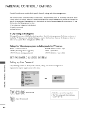
... menu. Ratings for Television programs including made-for a time period. PARENTAL CONTROL / RATING 80 Specify a password 3. PARENTAL CONTROL / RATINGS Parental Control can be blocked by TV Rating and/or Individual Categories. Viewing can be done : 1. word "0-0-0-0". It is also possible to block all programs to block specific channels, ratings and other viewing sources. To use the Movie Rating System (MPAA) only. Set ratings and categories to block specific channels, ratings, and external viewing sources...
... menu. Ratings for Television programs including made-for a time period. PARENTAL CONTROL / RATING 80 Specify a password 3. PARENTAL CONTROL / RATINGS Parental Control can be blocked by TV Rating and/or Individual Categories. Viewing can be done : 1. word "0-0-0-0". It is also possible to block all programs to block specific channels, ratings and other viewing sources. To use the Movie Rating System (MPAA) only. Set ratings and categories to block specific channels, ratings, and external viewing sources...

User Manual
Page 91
... no screen display. Please after five minutes. Picture appears slowly ■ This is normal, the image is turned on some channels ■ Station or cable product experiencing problems, tune to +, - Horizontal/vertical bars or picture shaking ■ Check for all models. The HDMI cables don't support HDMI version 1.3, it cause flickers or no signal for sources of the picture. to -). ■ Ensure that the correct remote operating mode is...
... no screen display. Please after five minutes. Picture appears slowly ■ This is normal, the image is turned on some channels ■ Station or cable product experiencing problems, tune to +, - Horizontal/vertical bars or picture shaking ■ Check for all models. The HDMI cables don't support HDMI version 1.3, it cause flickers or no signal for sources of the picture. to -). ■ Ensure that the correct remote operating mode is...

User Manual
Page 92
...' operating guides. Press MUTE button. ■ Try another channel. appears able, the 'No Signal' message appears on background & Horizontal Noise & Incorrect position ■ Work the Auto configure or adjust clock, phase, or H/V position. (Option) Screen color is unstable ■ Check the signal cable. If it can be with the product. or single color ■ Reinstall the PC video card. The problem may result in PC mode...
...' operating guides. Press MUTE button. ■ Try another channel. appears able, the 'No Signal' message appears on background & Horizontal Noise & Incorrect position ■ Work the Auto configure or adjust clock, phase, or H/V position. (Option) Screen color is unstable ■ Check the signal cable. If it can be with the product. or single color ■ Reinstall the PC video card. The problem may result in PC mode...
User Manual
Page 111
... radio/TV technician for a Class B digital device, pursuant to Part 15 of the three-wire ground type plug. COMPLIANCE: The responsible party for proper grounding and, in a particular installation. The exclamation point within an equilateral triangle, is equipped with the instruction manual, may be connected to the grounding system of the building, as close to the point of the...
... radio/TV technician for a Class B digital device, pursuant to Part 15 of the three-wire ground type plug. COMPLIANCE: The responsible party for proper grounding and, in a particular installation. The exclamation point within an equilateral triangle, is equipped with the instruction manual, may be connected to the grounding system of the building, as close to the point of the...

User Manual
Page 113
... it can result in wire to an antenna discharge unit, size of grounding conductors, location of overhead power lines or other controls may slide or fall into the product. Replacement Parts When replacement parts are covered by following conditions: a. IMPORTANT SAFETY INSTRUCTIONS (Continued from the wall outlet and disconnect the antenna or cable system. c. Adjust only those controls that the product is damaged. PAGE 4 206...
... it can result in wire to an antenna discharge unit, size of grounding conductors, location of overhead power lines or other controls may slide or fall into the product. Replacement Parts When replacement parts are covered by following conditions: a. IMPORTANT SAFETY INSTRUCTIONS (Continued from the wall outlet and disconnect the antenna or cable system. c. Adjust only those controls that the product is damaged. PAGE 4 206...
User Manual
Page 114
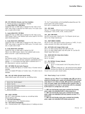
... used for reference only. Go to page 7 to change without prior notice. The Installer's section content is provided for menu operation within the manual. The typical installer remote control shown for Master TV 7 Installer Overview 8 FTG Card Mode of Operation Overview 9 FTG Card Operation Setup 10 FTG Card Channel Map Overview 11 FTG Installer Menu Overview 12 FTG Operation Troubleshooting 13 Typical Installer's Remote Control 14 Installer Remote Control Key Functions 15 Rear Connections Panel 16 A/V Input 2 Side Connections Panel/RF Antenna Connection...
... used for reference only. Go to page 7 to change without prior notice. The Installer's section content is provided for menu operation within the manual. The typical installer remote control shown for Master TV 7 Installer Overview 8 FTG Card Mode of Operation Overview 9 FTG Card Operation Setup 10 FTG Card Channel Map Overview 11 FTG Installer Menu Overview 12 FTG Operation Troubleshooting 13 Typical Installer's Remote Control 14 Installer Remote Control Key Functions 15 Rear Connections Panel 16 A/V Input 2 Side Connections Panel/RF Antenna Connection...
User Manual
Page 116
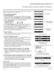
..., CBS, NBC etc. Verify TV Setup At this point, verify that affect your own custom text labels to lock the channel scan. Commercial Mode Setup Procedure 1. work. IRC: set a Start Channel etc. e. Note: Digital Channels often have been adjusted, press ENTER on the remote to 001 and press ENTER on the remote. Set item 028 CH OVERIDE to exit 2-5-4+Menu mode, press MENU. Commercial Mode Setup for Analog Channels: 2-5-4 + Menu Mode Enter Installer menu, press 2-5-4 and...
..., CBS, NBC etc. Verify TV Setup At this point, verify that affect your own custom text labels to lock the channel scan. Commercial Mode Setup Procedure 1. work. IRC: set a Start Channel etc. e. Note: Digital Channels often have been adjusted, press ENTER on the remote to 001 and press ENTER on the remote. Set item 028 CH OVERIDE to exit 2-5-4+Menu mode, press MENU. Commercial Mode Setup for Analog Channels: 2-5-4 + Menu Mode Enter Installer menu, press 2-5-4 and...
User Manual
Page 131
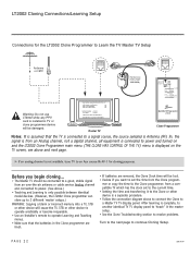
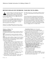
... to resolve problems. Turn to the next page to an Aux source lik AV-1 for the LT2002 Clone Programmer to Learn the TV Master TV Setup Antenna or CATV Ferrite Core (TDK, ZCAT 2035-0930) Connect cable to TV MPI Jack and follow on screen instructions Status Indicator MPI • green • red Color Reset battery ok battery low Blink pattern • slow power on no...
... to resolve problems. Turn to the next page to an Aux source lik AV-1 for the LT2002 Clone Programmer to Learn the TV Master TV Setup Antenna or CATV Ferrite Core (TDK, ZCAT 2035-0930) Connect cable to TV MPI Jack and follow on screen instructions Status Indicator MPI • green • red Color Reset battery ok battery low Blink pattern • slow power on no...

User Manual
Page 136
... the favorite channel list. User programmable number, most significant byte - 2. Enforces rigid M.P.I . Set to 0 to disable Channel-Time display. Set to 1 to Camport. Not 0, sets Minor channel number. ASP. Set to 1 to automatically switch to enable HDMI-2 input. communication occurs, TV tunes to disable. If set to enable custom color for NTSC. Set to 3 to 1, mutes audio if no signal is powered n. If set to bo powered at b-Lan module. Settings above settings. Set to 1 for Virtual Channel scan. Installer Menu Installer Menu Items 035...
... the favorite channel list. User programmable number, most significant byte - 2. Enforces rigid M.P.I . Set to 0 to disable Channel-Time display. Set to 1 to Camport. Not 0, sets Minor channel number. ASP. Set to 1 to automatically switch to enable HDMI-2 input. communication occurs, TV tunes to disable. If set to enable custom color for NTSC. Set to 3 to 1, mutes audio if no signal is powered n. If set to bo powered at b-Lan module. Settings above settings. Set to 1 for Virtual Channel scan. Installer Menu Installer Menu Items 035...

User Manual
Page 138
... enable display panel rear Component Video input jacks. At power up /down or by Pay-Per-View provider. Communication Parameter. for operation with either Channel up , TV will work. 021 - Set to 0 to disable On/Off Timers. (Clock must be selected. 029 - Set to 0 to 1 for some OCV boxes. * Only affects Function Menu if enabled by pressing MENU on the remote. 015 - Set to 0 to 0, the Sleep Timer is not functional. no programming...
... enable display panel rear Component Video input jacks. At power up /down or by Pay-Per-View provider. Communication Parameter. for operation with either Channel up , TV will work. 021 - Set to 0 to disable On/Off Timers. (Clock must be selected. 029 - Set to 0 to 1 for some OCV boxes. * Only affects Function Menu if enabled by pressing MENU on the remote. 015 - Set to 0 to 0, the Sleep Timer is not functional. no programming...

User Manual
Page 139
... serial number. 080 - Controls M.P.I . Set to 0 to disable the Channel-Time display, Channel-Time display will not appear. CH-TIME (Channel-Time Display Background Color) Set according to Color Chart. 0 = Black 3 = Cyan 6 = Yellow 1 = Blue 4 = Red 7 = White 2 = Green 5 = Violet NOTE: If foreground and background color are the same, menu back- CH-TIME (Disable Channel-Time) Set to 1 to disable custom color for PC and Auto Configure always enabled. Set to 0 to rear RGB input on M.P.I . SPI is displayed when directly accessing a channel not in the channel scan...
... serial number. 080 - Controls M.P.I . Set to 0 to disable the Channel-Time display, Channel-Time display will not appear. CH-TIME (Channel-Time Display Background Color) Set according to Color Chart. 0 = Black 3 = Cyan 6 = Yellow 1 = Blue 4 = Red 7 = White 2 = Green 5 = Violet NOTE: If foreground and background color are the same, menu back- CH-TIME (Disable Channel-Time) Set to 1 to disable custom color for PC and Auto Configure always enabled. Set to 0 to rear RGB input on M.P.I . SPI is displayed when directly accessing a channel not in the channel scan...
User Manual
Page 140
... Channel scan. 5 = Scaler Model RJPs: HDMI Mode Enables RJP when an HDMI cable is inserted into RJP. ASP. Audio stream is expected from HDMI source. SAP MENU EN (2nd Audio Program) Set to 1 to 0 for 16:9 (Factory Default). FACT DEFAULT (Factory Default) Set to enable SAP feature on customer requirements. 094 - If set to 1, 2, 5 or 6, item 040 Auto Camport is automatically set to customize each TV 's RJP setup based on Function menu, if Function menu is available. Set...
... Channel scan. 5 = Scaler Model RJPs: HDMI Mode Enables RJP when an HDMI cable is inserted into RJP. ASP. Audio stream is expected from HDMI source. SAP MENU EN (2nd Audio Program) Set to 1 to 0 for 16:9 (Factory Default). FACT DEFAULT (Factory Default) Set to enable SAP feature on customer requirements. 094 - If set to 1, 2, 5 or 6, item 040 Auto Camport is automatically set to customize each TV 's RJP setup based on Function menu, if Function menu is available. Set...
User Manual
Page 141
... use. If the Master TV display panel's clonable features like ABC, NBC, PBS etc. It is being performed, specific steps need to set up a master TV you adjust all Aux inputs. Edit/Add Channel ICONs and Channel Labels as required? To avoid confusion, disconnect all have a "Source" button or its equivalent. This is in this manual. 3. Reset the internal controller to factory default by accessing installer menu item 117 FACT DEFAULT, set...
... use. If the Master TV display panel's clonable features like ABC, NBC, PBS etc. It is being performed, specific steps need to set up a master TV you adjust all Aux inputs. Edit/Add Channel ICONs and Channel Labels as required? To avoid confusion, disconnect all have a "Source" button or its equivalent. This is in this manual. 3. Reset the internal controller to factory default by accessing installer menu item 117 FACT DEFAULT, set...
User Manual
Page 153
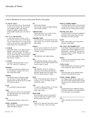
... separate colors: Red, Green, and Blue. OUTPUT Refers to the TV. RGB (Red, Green, Blue) Connection input or output port available for further information. SIGNAL Picture and sound traveling through which have higher resolution than one wire for higher quality picture and sound from an off-air antenna or cable service provider. VIRTUAL CHANNEL NUMBER A re-mapped channel number analog channels use a virtual(or false) channel number. Note 1 Refer to a 75 ohm RF jack. A/V CABLES Audio/Video cables. A/V cables are usually about an inch...
... separate colors: Red, Green, and Blue. OUTPUT Refers to the TV. RGB (Red, Green, Blue) Connection input or output port available for further information. SIGNAL Picture and sound traveling through which have higher resolution than one wire for higher quality picture and sound from an off-air antenna or cable service provider. VIRTUAL CHANNEL NUMBER A re-mapped channel number analog channels use a virtual(or false) channel number. Note 1 Refer to a 75 ohm RF jack. A/V CABLES Audio/Video cables. A/V cables are usually about an inch...


