Owners Manual
Page 2
... in a particular installation. This equipment generates, uses and can be determined by turning the equipment off and on a circuit different from LG Electronics. Increase the separation between the equipment and receiver. - CAUTION Do not attempt to modify this product to Part 15 of the ...National Electric Code (U.S.A.). Unauthorized modification could void the user's authority to which the receiver is connected. - NOTE TO CABLE/TV INSTALLER This reminder is encouraged to try to correct the interference by the party responsible for proper grounding...
... in a particular installation. This equipment generates, uses and can be determined by turning the equipment off and on a circuit different from LG Electronics. Increase the separation between the equipment and receiver. - CAUTION Do not attempt to modify this product to Part 15 of the ...National Electric Code (U.S.A.). Unauthorized modification could void the user's authority to which the receiver is connected. - NOTE TO CABLE/TV INSTALLER This reminder is encouraged to try to correct the interference by the party responsible for proper grounding...
Owners Manual
Page 4
...telephone wires, lightening rods, or gas pipes. that you turn off this product to fall into the product, and do not expose this unit by connecting it is recommend that appliance and has no additional outlets or branch circuits. Do not overload wall outlets. Any of the appliance, and have a qualified... an impact shock or any objects to rain, moisture or other liquids. Protect the power cord from the AC power source even if you connect the earth ground wire to dripping or splashing and do grasp the plug when unplugging the power cord. Do not use of these conditions could...
...telephone wires, lightening rods, or gas pipes. that you turn off this product to fall into the product, and do not expose this unit by connecting it is recommend that appliance and has no additional outlets or branch circuits. Do not overload wall outlets. Any of the appliance, and have a qualified... an impact shock or any objects to rain, moisture or other liquids. Protect the power cord from the AC power source even if you connect the earth ground wire to dripping or splashing and do grasp the plug when unplugging the power cord. Do not use of these conditions could...
Owners Manual
Page 5
... or benzene. 22 Moving Make sure the product is proper ventilation. Section 810 of time. Do not install in . Avoid touching the LCD screen or holding your local authority. 5 Do not spray water or other materials (e.g.) plastic while plugged in excessively dusty places. 24 If.... This is normal, there is turned on the monitor's performance. Disposal of this product contains a small amount of antenna discharge unit, connection to provide some temporary dis- Do not install in a confined space such as to grounding electrodes and requirements for long periods of the...
... or benzene. 22 Moving Make sure the product is proper ventilation. Section 810 of time. Do not install in . Avoid touching the LCD screen or holding your local authority. 5 Do not spray water or other materials (e.g.) plastic while plugged in excessively dusty places. 24 If.... This is normal, there is turned on the monitor's performance. Disposal of this product contains a small amount of antenna discharge unit, connection to provide some temporary dis- Do not install in a confined space such as to grounding electrodes and requirements for long periods of the...
Owners Manual
Page 6
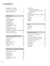
... the TV to a Desk 17 Securing the TV to the wall to prevent falling when the TV is used on a stand 18 Antenna or Cable Connection 19 EXTERNAL EQUIPMENT SETUP HD Receiver Setup 20 DVD Setup 23 VCR Setup 25 Other A/V Source Setup 27 USB... Connection 28 Audio out Connection 29 PC Setup 30 WATCHING TV / CHANNEL CONTROL Remote Control Functions 36 Turning On TV 38 Channel Selection 38 Volume Adjustment 38 Initial Setting 39 ...
... the TV to a Desk 17 Securing the TV to the wall to prevent falling when the TV is used on a stand 18 Antenna or Cable Connection 19 EXTERNAL EQUIPMENT SETUP HD Receiver Setup 20 DVD Setup 23 VCR Setup 25 Other A/V Source Setup 27 USB... Connection 28 Audio out Connection 29 PC Setup 30 WATCHING TV / CHANNEL CONTROL Remote Control Functions 36 Turning On TV 38 Channel Selection 38 Volume Adjustment 38 Initial Setting 39 ...
Owners Manual
Page 9
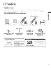
...OK CH VOL 2 3 6 BED1 BED2 1.5V 1.5V Owner's Manual CD Manual Installer Remote Control, User Remote Control, Batteries Batteries Power Cord (Except 47LH300C) x 4 Screws for stand assembly Screw for stand fixing (Refer to P.12) (Refer to P.17) Protection Cover (Refer to P.13) Protective Bracket... and Bolt for Power Cord (Refer to maintain standards compliance. 9 Option Extras D-sub 15 pin Cable When using the VGA (D-sub 15 pin cable) PC connection, the user must use shielded signal interface cables with ferrite cores to P.15) Not included with all models Polishing Cloth ...
...OK CH VOL 2 3 6 BED1 BED2 1.5V 1.5V Owner's Manual CD Manual Installer Remote Control, User Remote Control, Batteries Batteries Power Cord (Except 47LH300C) x 4 Screws for stand assembly Screw for stand fixing (Refer to P.12) (Refer to P.17) Protection Cover (Refer to P.13) Protective Bracket... and Bolt for Power Cord (Refer to maintain standards compliance. 9 Option Extras D-sub 15 pin Cable When using the VGA (D-sub 15 pin cable) PC connection, the user must use shielded signal interface cables with ferrite cores to P.15) Not included with all models Polishing Cloth ...
Owners Manual
Page 11
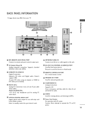
... control. 9 SPEAKER OUT PORT Used for external speaker jack. 10 COMPONENT IN Analog Connection. Uses a D-sub 15 pin cable (VGA cable). Caution: Never attempt to DVI cable (not included). 4 RGB IN (PC) Analog PC Connection. AUDIO IN (RGB/DVI) 1/8" (0.32 cm) headphone jack for analog PC audio... input. 5 OPTICAL DIGITAL AUDIO OUT Digital optical audio output for Service or Hotel mode. 3 HDMI/DVI IN, HDMI IN Digital Connection...
... control. 9 SPEAKER OUT PORT Used for external speaker jack. 10 COMPONENT IN Analog Connection. Uses a D-sub 15 pin cable (VGA cable). Caution: Never attempt to DVI cable (not included). 4 RGB IN (PC) Analog PC Connection. AUDIO IN (RGB/DVI) 1/8" (0.32 cm) headphone jack for analog PC audio... input. 5 OPTICAL DIGITAL AUDIO OUT Digital optical audio output for Service or Hotel mode. 3 HDMI/DVI IN, HDMI IN Digital Connection...
Owners Manual
Page 15
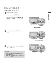
... as shown. 3 Put the cables inside the CABLE MANAGEMENT CLIP and snap it closed. ! It will help prevent the power cable from your TV. 1 Connect the cables as necessary. PROTECTIVE BRACKET CABLE MANAGEMENT CLIP 15 PREPARATION CABLE MANAGEMENT I Image shown may be broken. If the TV is dropped, you may... be injured or the product may differ from being removed by accident. 2 Install the CABLE MANAGEMENT CLIP as shown. To connect additional equipment, see the EXTERNAL EQUIPMENT SETUP section. NOTE G Do not hold the CABLE MANAGEMENT CLIP when moving the TV. -
... as shown. 3 Put the cables inside the CABLE MANAGEMENT CLIP and snap it closed. ! It will help prevent the power cable from your TV. 1 Connect the cables as necessary. PROTECTIVE BRACKET CABLE MANAGEMENT CLIP 15 PREPARATION CABLE MANAGEMENT I Image shown may be broken. If the TV is dropped, you may... be injured or the product may differ from being removed by accident. 2 Install the CABLE MANAGEMENT CLIP as shown. To connect additional equipment, see the EXTERNAL EQUIPMENT SETUP section. NOTE G Do not hold the CABLE MANAGEMENT CLIP when moving the TV. -
Owners Manual
Page 16
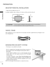
... left or right direction by following the clearance recommendations. G Do not mount near or above any type of the Kensington company. Connect the Kensington Security System cable as notebook PCs and LCD projectors. KENSINGTON SECURITY SYSTEM I Image shown may differ from the wall. 4 inches 4 inches 4 inches 4 inches CAUTION G Ensure adequate ventilation by...
... left or right direction by following the clearance recommendations. G Do not mount near or above any type of the Kensington company. Connect the Kensington Security System cable as notebook PCs and LCD projectors. KENSINGTON SECURITY SYSTEM I Image shown may differ from the wall. 4 inches 4 inches 4 inches 4 inches CAUTION G Ensure adequate ventilation by...
Owners Manual
Page 19
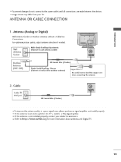
... the devices. Cable Cable TV Wall Jack RF Coaxial Wire (75 ohm) ACNATBELNENIAN/ I To prevent damage do not connect to bend the copper wire when connecting the antenna. 2. I If the antenna is not installed properly, contact your TV. PREPARATION I To improve the picture... quality in a poor signal area, please purchase a signal amplifier and install properly. ANTENNA OR CABLE CONNECTION 1. Wall Antenna Socket Multi-family Dwellings/Apartments (Connect to wall antenna socket) ANTENNA/ CABLE IN Outdoor Antenna (VHF, UHF) RF Coaxial Wire (75 ohm) Single-...
... the devices. Cable Cable TV Wall Jack RF Coaxial Wire (75 ohm) ACNATBELNENIAN/ I To prevent damage do not connect to bend the copper wire when connecting the antenna. 2. I If the antenna is not installed properly, contact your TV. PREPARATION I To improve the picture... quality in a poor signal area, please purchase a signal amplifier and install properly. ANTENNA OR CABLE CONNECTION 1. Wall Antenna Socket Multi-family Dwellings/Apartments (Connect to wall antenna socket) ANTENNA/ CABLE IN Outdoor Antenna (VHF, UHF) RF Coaxial Wire (75 ohm) Single-...
Owners Manual
Page 20
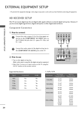
... receive digital over-the-air/digital cable signals without an external digital set -top box or other digital external device. How to connect 1 Connect the video outputs (Y, PB, PR) of the digital set-top box to the COMPONENT IN VIDEO jacks on the remote control....COMPONENT IN L AUDIO R L R SPEAKER OUT /DVI IN REMO CONTRO Supported Resolutions Signal Component 480i Yes 480p Yes 720p Yes 1080i Yes 1080p Yes HDMI No Yes Yes Yes Yes 20 Y, CB/PB, CR/PR Resolution Horizontal Vertical Frequency(KHz) Frequency(Hz) 720x480i 720x480p 1280x720p 1920x1080i 1920x1080p ...
... receive digital over-the-air/digital cable signals without an external digital set -top box or other digital external device. How to connect 1 Connect the video outputs (Y, PB, PR) of the digital set-top box to the COMPONENT IN VIDEO jacks on the remote control....COMPONENT IN L AUDIO R L R SPEAKER OUT /DVI IN REMO CONTRO Supported Resolutions Signal Component 480i Yes 480p Yes 720p Yes 1080i Yes 1080p Yes HDMI No Yes Yes Yes Yes 20 Y, CB/PB, CR/PR Resolution Horizontal Vertical Frequency(KHz) Frequency(Hz) 720x480i 720x480p 1280x720p 1920x1080i 1920x1080p ...
Owners Manual
Page 21
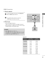
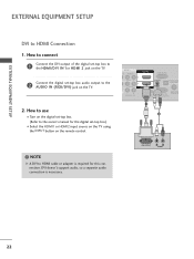
....00 23.976 24.00 29.97 30.00 59.94 60.00 21 How to connect 1 Connect the digital set-top box to the owner's manual for the digital set -top box. (Refer to the HDMI/DVI I Select the HDMI1 or HDMI2 input source on the TV using the INPUT button on... the TV. 2 No separate audio connection is necessary. How to use the latest cables that support HDMI version 1.3. HDMI supports both audio and video. 2. If the HDMI cables don't support HDMI version 1.3, it can cause flickers or no screen display. In this case use I Turn...
....00 23.976 24.00 29.97 30.00 59.94 60.00 21 How to connect 1 Connect the digital set-top box to the owner's manual for the digital set -top box. (Refer to the HDMI/DVI I Select the HDMI1 or HDMI2 input source on the TV using the INPUT button on... the TV. 2 No separate audio connection is necessary. How to use the latest cables that support HDMI version 1.3. HDMI supports both audio and video. 2. If the HDMI cables don't support HDMI version 1.3, it can cause flickers or no screen display. In this case use I Turn...
Owners Manual
Page 22
... DVI output of the digital set-top box to the AUDIO IN (RGB/DVI) jack on the TV. 2. NOTE G A DVI to HDMI Connection 1. AV IN 1 O AUDIO 2 L(MONO) R 1 L AUDIO R L R SPEAKER OUT RGB IN (PC) AUDIO IN /DVI IN (RGB/DVI) OPTICAL DIGIT AUDIO OUT REMOTE RS-232C IN ... on the digital set-top box. (Refer to the owner's manual for this connection. DVI doesn't support audio, so a separate audio connection is required for the digital set -top box audio output to the HDMI/DVI IN 1or HDMI 2 jack on the TV. 2 Connect the digital set -top box.) I Turn on the remote control.
... DVI output of the digital set-top box to the AUDIO IN (RGB/DVI) jack on the TV. 2. NOTE G A DVI to HDMI Connection 1. AV IN 1 O AUDIO 2 L(MONO) R 1 L AUDIO R L R SPEAKER OUT RGB IN (PC) AUDIO IN /DVI IN (RGB/DVI) OPTICAL DIGIT AUDIO OUT REMOTE RS-232C IN ... on the digital set-top box. (Refer to the owner's manual for this connection. DVI doesn't support audio, so a separate audio connection is required for the digital set -top box audio output to the HDMI/DVI IN 1or HDMI 2 jack on the TV. 2 Connect the digital set -top box.) I Turn on the remote control.
Owners Manual
Page 23
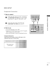
Match the jack colors (Y = green, PB = blue, and PR = red). 2 Connect the audio outputs of the DVD to the DVD player's manual for operating instructions. I Turn on DVD player Y Y PB PR PB PR B-Y R-Y Cb Cr Pb ... on the TV. 2. Component ports on the TV Y Y Video output ports Y on the DVD player, insert a DVD. Component Input ports To get better picture quality, connect a DVD player to the COMPONENT IN AUDIO jacks on the remote control. How to use I Refer to the COMPONENT IN VIDEO jacks on the TV...
Match the jack colors (Y = green, PB = blue, and PR = red). 2 Connect the audio outputs of the DVD to the DVD player's manual for operating instructions. I Turn on DVD player Y Y PB PR PB PR B-Y R-Y Cb Cr Pb ... on the TV. 2. Component ports on the TV Y Y Video output ports Y on the DVD player, insert a DVD. Component Input ports To get better picture quality, connect a DVD player to the COMPONENT IN AUDIO jacks on the remote control. How to use I Refer to the COMPONENT IN VIDEO jacks on the TV...
Owners Manual
Page 24
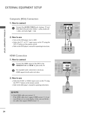
.../DVI) OPTICAL AUDIO REMOTE RS-232C IN ACNATB CONTROL IN (CONTROL&SERVICE) 1 ! NOTE G Check HDMI cable over version 1.3. HDMI OUTPUT 24 I Refer to use I Turn on the TV. 2 No separated audio connection is necessary. HDMI Connection 1. How to connect 1 Connect the HDMI output of the DVD to connect 1 Connect the AUDIO/VIDEO jacks between TV and DVD. How to the...
.../DVI) OPTICAL AUDIO REMOTE RS-232C IN ACNATB CONTROL IN (CONTROL&SERVICE) 1 ! NOTE G Check HDMI cable over version 1.3. HDMI OUTPUT 24 I Refer to use I Turn on the TV. 2 No separated audio connection is necessary. HDMI Connection 1. How to connect 1 Connect the HDMI output of the DVD to connect 1 Connect the AUDIO/VIDEO jacks between TV and DVD. How to the...
Owners Manual
Page 25
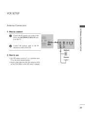
... 3 or 4 and then tune TV to the same channel number. How to use I Insert a video tape into the VCR and press PLAY on the TV. 2 Connect the antenna cable to the VCR owner's manual.) 1 ANT OUT S-VIDEO VIDEO L R AUDIO ANT IN OUTPUT SWITCH Wall Jack 2 Antenna 25 How to... connect 1 Connect the RF antenna out socket of the VCR to the ANTENNA/CABLE IN socket on the VCR. (Refer to the RF antenna in socket of ...
... 3 or 4 and then tune TV to the same channel number. How to use I Insert a video tape into the VCR and press PLAY on the TV. 2 Connect the antenna cable to the VCR owner's manual.) 1 ANT OUT S-VIDEO VIDEO L R AUDIO ANT IN OUTPUT SWITCH Wall Jack 2 Antenna 25 How to... connect 1 Connect the RF antenna out socket of the VCR to the ANTENNA/CABLE IN socket on the VCR. (Refer to the RF antenna in socket of ...
Owners Manual
Page 26
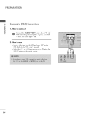
NOTE G If you have a mono VCR, connect the audio cable from the VCR to connect 1 Connect the AUDIO/VIDEO jacks between TV and VCR. PREPARATION PREPARATION Composite (RCA) Connection 1. RJP AV IN 1 VIDEO AUDIO 2 L(MONO) R 1 VIDEO COMPONENT IN L AUDIO R L R SPEAKER OUT 1 /DVI IN REMO CONTR ANT IN S-VIDEO VIDEO L R AUDIO ANT OUT OUTPUT SWITCH ...
NOTE G If you have a mono VCR, connect the audio cable from the VCR to connect 1 Connect the AUDIO/VIDEO jacks between TV and VCR. PREPARATION PREPARATION Composite (RCA) Connection 1. RJP AV IN 1 VIDEO AUDIO 2 L(MONO) R 1 VIDEO COMPONENT IN L AUDIO R L R SPEAKER OUT 1 /DVI IN REMO CONTR ANT IN S-VIDEO VIDEO L R AUDIO ANT OUT OUTPUT SWITCH ...
Owners Manual
Page 27
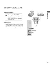
I Select the A V 1 or A V 2 input source on the TV using the INPUT button on the remote control. Match the jack colors. (Video = yellow, Audio Left = white, and Audio Right = red) 2. PREPARATION OTHER A/V SOURCE SETUP 1. How to connect 1 Connect the AUDIO/VIDEO jacks between TV and external equipment. USB IN Camcorder Video Game Set VIDEO L R 1 VIDEO L/MONO AUDIO R AV IN 2 27 How to use I Operate the corresponding external equipment.
I Select the A V 1 or A V 2 input source on the TV using the INPUT button on the remote control. Match the jack colors. (Video = yellow, Audio Left = white, and Audio Right = red) 2. PREPARATION OTHER A/V SOURCE SETUP 1. How to connect 1 Connect the AUDIO/VIDEO jacks between TV and external equipment. USB IN Camcorder Video Game Set VIDEO L R 1 VIDEO L/MONO AUDIO R AV IN 2 27 How to use I Operate the corresponding external equipment.

Owners Manual
Page 28
EXTERNAL EQUIPMENT SETUP USB CONNECTION 1. How to connect 1 Connect the USB device to use the USB function. (G p.54) VIDEO L/MONO AUDIO R USB IN or 1 Memory Key AV IN 2 EXTERNAL EQUIPMENT SETUP 28 How to the USB I N jack, you use I After connecting the USB I N jack on the side of TV. 2.
EXTERNAL EQUIPMENT SETUP USB CONNECTION 1. How to connect 1 Connect the USB device to use the USB function. (G p.54) VIDEO L/MONO AUDIO R USB IN or 1 Memory Key AV IN 2 EXTERNAL EQUIPMENT SETUP 28 How to the USB I N jack, you use I After connecting the USB I N jack on the side of TV. 2.
Owners Manual
Page 29
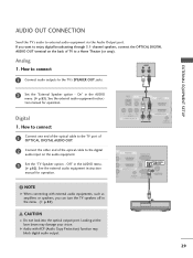
... ACP (Audio Copy Protection) function may damage your vision. See the external audio equipment instruction manual for operation. How to connect L R 1 Connect audio outputs to external audio equipment via the Audio Output port. G Audio with external audio equipments, such as amplifiers or speakers, ...you want to a Home Theater (or amp). Looking at the laser beam may block digital audio output. 29 EXTERNAL EQUIPMENT SETUP AUDIO OUT CONNECTION Send the TV's audio to the TV's SPEAKER OUT jacks. 2 Set the "External Speaker option - If you can turn the TV speakers...
... ACP (Audio Copy Protection) function may damage your vision. See the external audio equipment instruction manual for operation. How to connect L R 1 Connect audio outputs to external audio equipment via the Audio Output port. G Audio with external audio equipments, such as amplifiers or speakers, ...you want to a Home Theater (or amp). Looking at the laser beam may block digital audio output. 29 EXTERNAL EQUIPMENT SETUP AUDIO OUT CONNECTION Send the TV's audio to the TV's SPEAKER OUT jacks. 2 Set the "External Speaker option - If you can turn the TV speakers...
Owners Manual
Page 30
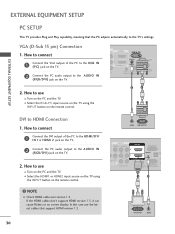
... that support HDMI version 1.3. 30 AUDIO RGB OUTPUT AV IN 1 VIDEO AUDIO 2 L(MONO) R 1 EO ENT IN L AUDIO R L R SPEAKER OUT RGB IN (PC) AUDIO IN /DVI IN (RGB/DVI) OPTI AU A REMOTE RS-232C IN C CONTROL IN (CONTROL&SERVICE) 1 2 DVI OUTPUT AUDIO I Turn on the TV. 2. How to connect 1 Connect the VGA output of the...
... that support HDMI version 1.3. 30 AUDIO RGB OUTPUT AV IN 1 VIDEO AUDIO 2 L(MONO) R 1 EO ENT IN L AUDIO R L R SPEAKER OUT RGB IN (PC) AUDIO IN /DVI IN (RGB/DVI) OPTI AU A REMOTE RS-232C IN C CONTROL IN (CONTROL&SERVICE) 1 2 DVI OUTPUT AUDIO I Turn on the TV. 2. How to connect 1 Connect the VGA output of the...


