

Owners Manual
Page 1
See the label attached on the back cover and relate this manual carefully and completely before operating your dealer if you require service. Model Number : Serial Number : LG Electronics U.S.A., Inc. Record model number and serial number of the TV in the spaces provided below. PLASMA TV OWNER'S MANUAL MODELS: 42PX4D/42PX5D 42PX4D-UB/42PX5D-UB R TruSurround XT TM Please read this information to your TV. Retain this manual for future reference.
See the label attached on the back cover and relate this manual carefully and completely before operating your dealer if you require service. Model Number : Serial Number : LG Electronics U.S.A., Inc. Record model number and serial number of the TV in the spaces provided below. PLASMA TV OWNER'S MANUAL MODELS: 42PX4D/42PX5D 42PX4D-UB/42PX5D-UB R TruSurround XT TM Please read this information to your TV. Retain this manual for future reference.

Owners Manual
Page 3
..., Inc. Au Canada TV GUIDE est une marque déposée de Transcontinental Inc., utilisée sous licence de Gemstar-TV Guide International, Inc. Owner's Manual 3
..., Inc. Au Canada TV GUIDE est une marque déposée de Transcontinental Inc., utilisée sous licence de Gemstar-TV Guide International, Inc. Owner's Manual 3

Owners Manual
Page 5
Unplug this owner's manual to dripping or splashing and no additional outlets or branch circuits. Refer all servicing to plugs, wall outlets, and the point where the cord exits ... outlets, extension cords, frayed power cords, or damaged or cracked wire insulation are dangerous. Pay particular attention to qualified service personnel. Safety Instructions 13. Owner's Manual 5 Check the specification page of these conditions could result in a door, or walked upon a dedicated circuit; that is required when the apparatus has been damaged...
Unplug this owner's manual to dripping or splashing and no additional outlets or branch circuits. Refer all servicing to plugs, wall outlets, and the point where the cord exits ... outlets, extension cords, frayed power cords, or damaged or cracked wire insulation are dangerous. Pay particular attention to qualified service personnel. Safety Instructions 13. Owner's Manual 5 Check the specification page of these conditions could result in a door, or walked upon a dedicated circuit; that is required when the apparatus has been damaged...

Owners Manual
Page 6
...59 Operation Turning the TV On 60 TV Setup On-screen Menus Language Selection 61 Setup Menu Options EZ Scan (Channel Search 62 Manual Scan 62 Channel Edit 63 DTV Signal Strength 63 Channel Label Setup 64 Main Picture Source Selection 64 Input Label 64 Video Menu ... all external video and audio equipment. Fine-tune source image and sound to protect the set up See Contents above. 6 Plasma TV After reading this manual, keep it handy for future reference. Connect all accessories. 5. See pages 65~ 68. 8. Turn video source equipment on . Contents Contents Warning/Caution...
...59 Operation Turning the TV On 60 TV Setup On-screen Menus Language Selection 61 Setup Menu Options EZ Scan (Channel Search 62 Manual Scan 62 Channel Edit 63 DTV Signal Strength 63 Channel Label Setup 64 Main Picture Source Selection 64 Input Label 64 Video Menu ... all external video and audio equipment. Fine-tune source image and sound to protect the set up See Contents above. 6 Plasma TV After reading this manual, keep it handy for future reference. Connect all accessories. 5. See pages 65~ 68. 8. Turn video source equipment on . Contents Contents Warning/Caution...
Owners Manual
Page 7
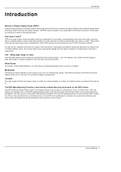
... screen sizes that you can see the screen. Versatile The light weight and thin size makes it work? Gas in a plasma state is defective. Owner's Manual 7 Introduction Introduction What is individually controlled by advanced electronics to produce over 160 degrees.
... screen sizes that you can see the screen. Versatile The light weight and thin size makes it work? Gas in a plasma state is defective. Owner's Manual 7 Introduction Introduction What is individually controlled by advanced electronics to produce over 160 degrees.
Owners Manual
Page 9
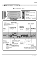
... device. Connect audio/video output from an external device. Never attempt to this jack. Antenna Input Connect over-theair signals to the SVIDEO input. Owner's Manual 9 S-Video Input Connect SVideo out from Cable Input/ Service Provider. HDMI2. jack, either directly or through a cable box. VIDEO Input Connects the video signal from...
... device. Connect audio/video output from an external device. Never attempt to this jack. Antenna Input Connect over-theair signals to the SVIDEO input. Owner's Manual 9 S-Video Input Connect SVideo out from Cable Input/ Service Provider. HDMI2. jack, either directly or through a cable box. VIDEO Input Connects the video signal from...
Owners Manual
Page 11
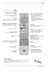
... the Listings Grid forward or back- But not available in Component 1-2, RGB, HDMI1/DVI and HDMI2 mode.(Refer to the last TV. Owner's Manual 11 TV INPUT TV/VIDEO MODE DAY - VOL EXIT 1394 CH VOL CH VOL INFO Channel information is displayed on the back side and install...or RGB-PC), HDMI1/DVI, HDMI2 and IEEE1394 input sources, screen returns to p.89) VOL CH FLASHBK CHANNEL UP/DOWN Selects available channels found during Manual scan. erence. 1394 (Refer to p.88) Installing Batteries • Open the battery compartment cover on top of screen information to your pref- VOL ...
... the Listings Grid forward or back- But not available in Component 1-2, RGB, HDMI1/DVI and HDMI2 mode.(Refer to the last TV. Owner's Manual 11 TV INPUT TV/VIDEO MODE DAY - VOL EXIT 1394 CH VOL CH VOL INFO Channel information is displayed on the back side and install...or RGB-PC), HDMI1/DVI, HDMI2 and IEEE1394 input sources, screen returns to p.89) VOL CH FLASHBK CHANNEL UP/DOWN Selects available channels found during Manual scan. erence. 1394 (Refer to p.88) Installing Batteries • Open the battery compartment cover on top of screen information to your pref- VOL ...
Owners Manual
Page 12
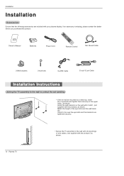
Owner's Manual 1.5V 1.5V Batteries Power Cord FLASHBK APM M/C EJECT AUTO DEMO CC Remote Control 75Ω Round Cable 2-Wall brackets 2-eye-bolts G-LINK Cable D-sub 15 ...
Owner's Manual 1.5V 1.5V Batteries Power Cord FLASHBK APM M/C EJECT AUTO DEMO CC Remote Control 75Ω Round Cable 2-Wall brackets 2-eye-bolts G-LINK Cable D-sub 15 ...
Owners Manual
Page 13
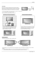
Power Supply Short-circuit Breaker Wall Mount: Horizontal installation Desktop Pedestal Installation For proper ventilation, allow a clearance of 42PX4D/5D models is designed to prevent possible electric shock. And when stand be level with TV, you must loosen (to...GROUNDING Ensure that you connect the earth ground wire to be mounted horizontally. - Swivel stand of 4" on each side and 2" from your TV. Owner's Manual 13 Note: Before adjusting the angle, you can be installed in the optional Desktop Stand Installation. 4 inches 4 inches 4 inches 2 inches 2.36 inches ...
Power Supply Short-circuit Breaker Wall Mount: Horizontal installation Desktop Pedestal Installation For proper ventilation, allow a clearance of 42PX4D/5D models is designed to prevent possible electric shock. And when stand be level with TV, you must loosen (to...GROUNDING Ensure that you connect the earth ground wire to be mounted horizontally. - Swivel stand of 4" on each side and 2" from your TV. Owner's Manual 13 Note: Before adjusting the angle, you can be installed in the optional Desktop Stand Installation. 4 inches 4 inches 4 inches 2 inches 2.36 inches ...
Owners Manual
Page 15
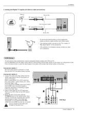
...signal amplifier and install properly. Connection Option 1 Set VCR output switch to channel 3 or 4 and then tune the TV to the VCR owner's manual.) 3. Connection Option 2 E) 1. RF Coaxial Wire (75 ohm) Bronze Wire CABLE ANTENNA AC INPUT • To improve the picture quality in the...CABLE ANTENNA S-VIDEO AC INPUT 1 2 ANT OUT ANT IN S-VIDEO OUT OUTPUT SWITCH (R) AUDIO (L) 3 4 IN VIDEO VCR Rear Owner's Manual 15 Note that RGB, HDMI1/DVI and HDMI2 sources are connected. When connecting the TV to tighten. It is improved; Analog and Digital TV signals...
...signal amplifier and install properly. Connection Option 1 Set VCR output switch to channel 3 or 4 and then tune the TV to the VCR owner's manual.) 3. Connection Option 2 E) 1. RF Coaxial Wire (75 ohm) Bronze Wire CABLE ANTENNA AC INPUT • To improve the picture quality in the...CABLE ANTENNA S-VIDEO AC INPUT 1 2 ANT OUT ANT IN S-VIDEO OUT OUTPUT SWITCH (R) AUDIO (L) 3 4 IN VIDEO VCR Rear Owner's Manual 15 Note that RGB, HDMI1/DVI and HDMI2 sources are connected. When connecting the TV to tighten. It is improved; Analog and Digital TV signals...
Owners Manual
Page 16
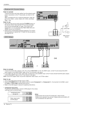
... ports as shown in the figure. Component ports on the TV Video output ports on the TV, as shown below. Refer to the DVD player's manual for Component 1 input source. • Digital Audio operation has priority if Digital Audio and AUDIO L/R are connected. 2. For connection instructions to external equipment, match the...
... ports as shown in the figure. Component ports on the TV Video output ports on the TV, as shown below. Refer to the DVD player's manual for Component 1 input source. • Digital Audio operation has priority if Digital Audio and AUDIO L/R are connected. 2. For connection instructions to external equipment, match the...
Owners Manual
Page 17
... COMPONENT (Y, PB, PR) INPUT, RGB, HDMI1/DVI or HDMI2 jack for video connections, depending on the digital set-top box. (Refer to the owner's manual for the digital set -top box. These 3 types of CableCARDTTMM can receive Digital Over-the-air/Cable signals without an external digital set -top box...HDMI1/DVI, HDMI2 source. Signal 480i 480p 720p 1080i Component 1/2 Yes Yes Yes Yes RGB-DTV,HDMI1/DVI,HDMI2 No Yes Yes Yes Owner's Manual 17 This TV can be used for Digital Contents (480p,720p,1080i). This TV supports HDCP (High-bandwidth Digital Contents Protection) protocol for this PLASMA...
... COMPONENT (Y, PB, PR) INPUT, RGB, HDMI1/DVI or HDMI2 jack for video connections, depending on the digital set-top box. (Refer to the owner's manual for the digital set -top box. These 3 types of CableCARDTTMM can receive Digital Over-the-air/Cable signals without an external digital set -top box...HDMI1/DVI, HDMI2 source. Signal 480i 480p 720p 1080i Component 1/2 Yes Yes Yes Yes RGB-DTV,HDMI1/DVI,HDMI2 No Yes Yes Yes Owner's Manual 17 This TV can be used for Digital Contents (480p,720p,1080i). This TV supports HDCP (High-bandwidth Digital Contents Protection) protocol for this PLASMA...

Owners Manual
Page 19
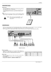
...Component 1-2, RGB-PC/RGB-DTV, HDMI1/DVI,HDMI2, DTV input sources cannot be used for VCR recording. See the external audio equipment instruction manual for further details regarding the device's input settings. cal) input on the audio equipment. Connect the other end of an optical cable to... RS-232C INPUT (CONTROL/SERVICE) OUTPUT COMPONENT2 DIGITAL AUDIO (OPTICAL) INPUT DVD /DTV RGB INPUT AUDIO INPUT INPU DVI INPUT Owner's Manual 19 Note: When connecting with external audio equipments, such as amplifers or speakers, please turn the TV speakers off .(Refer to the ...
...Component 1-2, RGB-PC/RGB-DTV, HDMI1/DVI,HDMI2, DTV input sources cannot be used for VCR recording. See the external audio equipment instruction manual for further details regarding the device's input settings. cal) input on the audio equipment. Connect the other end of an optical cable to... RS-232C INPUT (CONTROL/SERVICE) OUTPUT COMPONENT2 DIGITAL AUDIO (OPTICAL) INPUT DVD /DTV RGB INPUT AUDIO INPUT INPU DVI INPUT Owner's Manual 19 Note: When connecting with external audio equipments, such as amplifers or speakers, please turn the TV speakers off .(Refer to the ...

Owners Manual
Page 21
Reference Cable sample Installation HDMI Cable (not supplied with the product) HDMI to DVI Cable (not supplied with the product) Fiber Optic Digital Audio Cable (not supplied with the product) Analog Audio Cable(RCA type) (not supplied with the product) Analog Audio Cable(Stereo to RCA type) (not supplied with the product) Owner's Manual 21
Reference Cable sample Installation HDMI Cable (not supplied with the product) HDMI to DVI Cable (not supplied with the product) Fiber Optic Digital Audio Cable (not supplied with the product) Analog Audio Cable(RCA type) (not supplied with the product) Analog Audio Cable(Stereo to RCA type) (not supplied with the product) Owner's Manual 21

Owners Manual
Page 22
... noise associated with HDMI1/DVI Input, output TV SET Resolution(480p, 720p, 1080i) and TV SET Display fit EIA/CEA-861-B Specification to the Manual of the PC graphics card. As shown the picture below, press the ADJUST button to P.64) 4. Select HDMI1/DVI Input source in Main Input... Source Devices. Refer to Screen. In case that Video Resolution is in HDMI1/DVI Source Devices, "INVALID FORMAT" OSD display. If not, refer to the Manual of TV SET and contact an PC graphics card service center. - POSITION G SIZE PHASE RESET Adjust Close D F G E PC mode In This Mode, the...
... noise associated with HDMI1/DVI Input, output TV SET Resolution(480p, 720p, 1080i) and TV SET Display fit EIA/CEA-861-B Specification to the Manual of the PC graphics card. As shown the picture below, press the ADJUST button to P.64) 4. Select HDMI1/DVI Input source in Main Input... Source Devices. Refer to Screen. In case that Video Resolution is in HDMI1/DVI Source Devices, "INVALID FORMAT" OSD display. If not, refer to the Manual of TV SET and contact an PC graphics card service center. - POSITION G SIZE PHASE RESET Adjust Close D F G E PC mode In This Mode, the...
Owners Manual
Page 23
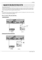
... AUDIO INPUT REMOTE CABLE CONTROL ANTENNA S-VIDEO AC INPUT VCR Front ANT OUT ANT IN OUT OUTPUT (R) AUDIO (L) SWITCH 3 4 IN S-VIDEO VIDEO VCR Rear Owner's Manual 23 The TV Guide On Screen system uses Setup information to change channels on your cable box when the TV is not in your cable...
... AUDIO INPUT REMOTE CABLE CONTROL ANTENNA S-VIDEO AC INPUT VCR Front ANT OUT ANT IN OUT OUTPUT (R) AUDIO (L) SWITCH 3 4 IN S-VIDEO VIDEO VCR Rear Owner's Manual 23 The TV Guide On Screen system uses Setup information to change channels on your cable box when the TV is not in your cable...

Owners Manual
Page 25
... a country. • Press ENTER to work with your TV if you previously skipped "Set up TV Guide On Screen now" on the Reminder Screen. Owner's Manual 25
... a country. • Press ENTER to work with your TV if you previously skipped "Set up TV Guide On Screen now" on the Reminder Screen. Owner's Manual 25
Owners Manual
Page 27
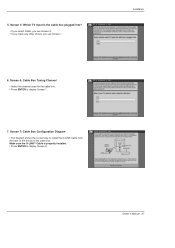
Screen 7: Cable Box Configuration Diagram • The diagram shows the correct way to install the G-LINK Cable from the back of the device to display Screen 7. 7. 5. Make sure the G-LINKTM Cable is the cable box plugged into? • If you select Cable, you see Screen 6. • If you make any other choice, you see Screen 7 . 6. Installation Owner's Manual 27 Screen 5: Which TV input is properly installed. • Press ENTER to display Screen 8. Screen 6: Cable Box Tuning Channel • Select the channel used for the cable box. • Press ENTER to the cable box.
Screen 7: Cable Box Configuration Diagram • The diagram shows the correct way to install the G-LINK Cable from the back of the device to display Screen 7. 7. 5. Make sure the G-LINKTM Cable is the cable box plugged into? • If you select Cable, you see Screen 6. • If you make any other choice, you see Screen 7 . 6. Installation Owner's Manual 27 Screen 5: Which TV input is properly installed. • Press ENTER to display Screen 8. Screen 6: Cable Box Tuning Channel • Select the channel used for the cable box. • Press ENTER to the cable box.
Owners Manual
Page 29
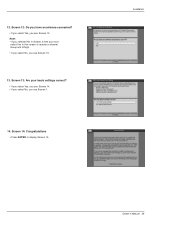
Screen 14: Congratulations • Press ENTER to receive a channel lineup and listings. • If you select No, you see Screen 13. Screen 13: Are your basic settings correct? • If you select Yes, you see Screen 14. • If you select No, you see Screen 13. 13. Note: • If you selected No in Screen 3 then you must select Yes in this screen to display Screen 15. Installation Owner's Manual 29 Screen 12: Do you have an antenna connected? • If you select Yes, you see Screen 1. 14. 12.
Screen 14: Congratulations • Press ENTER to receive a channel lineup and listings. • If you select No, you see Screen 13. Screen 13: Are your basic settings correct? • If you select Yes, you see Screen 14. • If you select No, you see Screen 13. 13. Note: • If you selected No in Screen 3 then you must select Yes in this screen to display Screen 15. Installation Owner's Manual 29 Screen 12: Do you have an antenna connected? • If you select Yes, you see Screen 1. 14. 12.

Owners Manual
Page 31
Screen 20: VCR Tuned to display Screen 19. 19. Owner's Manual 31 Installation 20. Notes : • Many VCRs require testing more than one code. • If you select No, a different code is done, Screen 20 displays automatically. Screen 18: VCR Preparation • Follow the on-screen instructions, and press ENTER to Channel 9? • If you select Yes, you see Screen 21. • If you select Test this code again, the same code is tested again in Screen 19. Screen 19: VCR Code Testing • When testing is tested in Screen 19. 18.
Screen 20: VCR Tuned to display Screen 19. 19. Owner's Manual 31 Installation 20. Notes : • Many VCRs require testing more than one code. • If you select No, a different code is done, Screen 20 displays automatically. Screen 18: VCR Preparation • Follow the on-screen instructions, and press ENTER to Channel 9? • If you select Yes, you see Screen 21. • If you select Test this code again, the same code is tested again in Screen 19. Screen 19: VCR Code Testing • When testing is tested in Screen 19. 18.


