
Owners Manual
Page 1
P/NO : SAC30708033 (0810-REV03) 0 (% LCD TV OWNER'S MANUAL 37LG50 42LG50 47LG50 52LG50 42LGSODC 47LGSODC 52LGSODC 42LG55 47 LGS5 Please read this your dealer when you require service. ibel attached on the back cover and quote _is information to your operating mber and serial number of the set.
P/NO : SAC30708033 (0810-REV03) 0 (% LCD TV OWNER'S MANUAL 37LG50 42LG50 47LG50 52LG50 42LGSODC 47LGSODC 52LGSODC 42LG55 47 LGS5 Please read this your dealer when you require service. ibel attached on the back cover and quote _is information to your operating mber and serial number of the set.

Owners Manual
Page 2
... for a Class B digital device, pursuant to correct the interference by turning the equipment off and on a circuit different from LG Electronics. This reminder is connected. -Consult the dealer or an experienced radio/TV technician for proper grounding and, in a residential installation. This equipment generates, uses and can be connected to the grounding...
... for a Class B digital device, pursuant to correct the interference by turning the equipment off and on a circuit different from LG Electronics. This reminder is connected. -Consult the dealer or an experienced radio/TV technician for proper grounding and, in a residential installation. This equipment generates, uses and can be connected to the grounding...

Owners Manual
Page 4
...examine the cord of your appliance, and if its appearance indicates damage or deterioration, unplug it to direct air conditioning. Do not touch the TV with the power cord plugged in fire or electric shock. on or over the apparatus (e.g. Power Supply O DISCONNECTING DEVICE FROM MAINS Mains plug ...appliance. Do not overload wall outlets. Pay particular attention to prevent possible electric shock (i.e. Do not make sure not to install the TV by an authorized servicer. Check the specification page of fire or electrical shock, do not drop onto the screen with an exact ...
...examine the cord of your appliance, and if its appearance indicates damage or deterioration, unplug it to direct air conditioning. Do not touch the TV with the power cord plugged in fire or electric shock. on or over the apparatus (e.g. Power Supply O DISCONNECTING DEVICE FROM MAINS Mains plug ...appliance. Do not overload wall outlets. Pay particular attention to prevent possible electric shock (i.e. Do not make sure not to install the TV by an authorized servicer. Check the specification page of fire or electrical shock, do not drop onto the screen with an exact ...

Owners Manual
Page 5
... directly on it can occur. @ ANTENNAS Outdoor antenna grounding If an outdoor antenna is proper ventilation. Section 810 of the TV. Ventilation Install your TV where there is installed, follow the precautions below. Ground Clamp NEC: National Electrical Code Antenna Lead in the vicinity of the...occur. Do not spray water or other materials (e.g.) plastic while plugged in the U.S.A. Do not clean with a soft cloth to carry larger TVs. An outdoor antenna system should not be located in Wire Antenna Discharge Unit (NEC Section 810-20) Grounding Conductor (NEC Section 810-21)...
... directly on it can occur. @ ANTENNAS Outdoor antenna grounding If an outdoor antenna is proper ventilation. Section 810 of the TV. Ventilation Install your TV where there is installed, follow the precautions below. Ground Clamp NEC: National Electrical Code Antenna Lead in the vicinity of the...occur. Do not spray water or other materials (e.g.) plastic while plugged in the U.S.A. Do not clean with a soft cloth to carry larger TVs. An outdoor antenna system should not be located in Wire Antenna Discharge Unit (NEC Section 810-20) Grounding Conductor (NEC Section 810-21)...
Owners Manual
Page 6
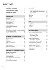
... Advanced Control - User Mode 60 - Picture Mode - Preset 58 - CONTENTS WARNING / CAUTION 2 SAFETY INSTRUCTIONS 3 FEATURE OF THIS TV 8 Accessories 9 Front Panel Information 10 Back Panel Information 11 Stand Instruction 12 VESA Wall Mounting 13 Cable Management 14 Desktop Pedestal Installation ...Scan (Auto Tuning 40 - Expert Control 61 Picture Improvement Technology 62 Advanced Control- Preset 59 Manual Picture Adjustment - Channel Editing 42 Input List 43 Input Label 44 AV Mode 45 SIMPLINK 46 Entry Modes 48 Photo List 49 Music List 53 Picture Size (Aspect...
... Advanced Control - User Mode 60 - Picture Mode - Preset 58 - CONTENTS WARNING / CAUTION 2 SAFETY INSTRUCTIONS 3 FEATURE OF THIS TV 8 Accessories 9 Front Panel Information 10 Back Panel Information 11 Stand Instruction 12 VESA Wall Mounting 13 Cable Management 14 Desktop Pedestal Installation ...Scan (Auto Tuning 40 - Expert Control 61 Picture Improvement Technology 62 Advanced Control- Preset 59 Manual Picture Adjustment - Channel Editing 42 Input List 43 Input Label 44 AV Mode 45 SIMPLINK 46 Entry Modes 48 Photo List 49 Music List 53 Picture Size (Aspect...

Owners Manual
Page 7
Auto Clock Setup 81 - User Mode 70 Clear Voice 71 Balance 72 TV Speakers On/Off Setup 73 Audio Reset 74 Stereo/SAP Broadcast Setup 75 Audio Language 76 On-Screen Menus Language Selection 77 Caption Mode - Analog ... 82 Auto On/Off Time Setting 83 Sleep Timer Setting 84 Auto Shut-off Setting 85 Set Password & Lock System 86 Channel Blocking 89 Movie & TV Rating 90 Downloadable Rating 95 External Input Blocking 96 Key lock 97 7
Auto Clock Setup 81 - User Mode 70 Clear Voice 71 Balance 72 TV Speakers On/Off Setup 73 Audio Reset 74 Stereo/SAP Broadcast Setup 75 Audio Language 76 On-Screen Menus Language Selection 77 Caption Mode - Analog ... 82 Auto On/Off Time Setting 83 Sleep Timer Setting 84 Auto Shut-off Setting 85 Set Password & Lock System 86 Channel Blocking 89 Movie & TV Rating 90 Downloadable Rating 95 External Input Blocking 96 Key lock 97 7

Owners Manual
Page 8
... the monitor's performance. Do not dispose of your local dealer to inquire about an ISF certified technician. FOR LCD TV _ If the TV feels cold to the regulations of this product with TV. Disposal of this product contains a small amount of time. "Dolby "and the double-D symbol are trademarks of... SRSLabs, Inc. On Disposal (Only Hg lamp used LCD TV) The fluorescent lamp used in this product must be carried out in accordance to the touch, there may produce some temporary distortion effects on the...
... the monitor's performance. Do not dispose of your local dealer to inquire about an ISF certified technician. FOR LCD TV _ If the TV feels cold to the regulations of this product with TV. Disposal of this product contains a small amount of time. "Dolby "and the double-D symbol are trademarks of... SRSLabs, Inc. On Disposal (Only Hg lamp used LCD TV) The fluorescent lamp used in this product must be carried out in accordance to the touch, there may produce some temporary distortion effects on the...

Owners Manual
Page 9
... to R12) Screw for stand fixing (Refer to R15) Polishing Cloth (This feature is missing, please contact the dealer where you purchased the TV. PREPARATION ACCESSORIES Ensure that the following accessories are included with your TV. Excessive pressure may differ from the images below. The accessories included may cause scratch or discoloration.
... to R12) Screw for stand fixing (Refer to R15) Polishing Cloth (This feature is missing, please contact the dealer where you purchased the TV. PREPARATION ACCESSORIES Ensure that the following accessories are included with your TV. Excessive pressure may differ from the images below. The accessories included may cause scratch or discoloration.

Owners Manual
Page 10
... Button MENU Button INPUT Button 10 PREPARATION FRONT PANELINFORMATION ,,,IImage shown may differ from your TV. -0 ""_NOTE: If your TV has a protection tape attached, remove the tape. _o And then wipe the TV with a cloth (If a polishing cloth is switched on. (Can be adjusted using... Power Indicator in standby mode. Illuminates blue when the set is included with your TV, use it). _o © z Intelligent Sensor Adjusts picture according surrounding conditions to the Power/Standby Indicator Illuminates red in the OPTION menu. ...
... Button MENU Button INPUT Button 10 PREPARATION FRONT PANELINFORMATION ,,,IImage shown may differ from your TV. -0 ""_NOTE: If your TV has a protection tape attached, remove the tape. _o And then wipe the TV with a cloth (If a polishing cloth is switched on. (Can be adjusted using... Power Indicator in standby mode. Illuminates blue when the set is included with your TV, use it). _o © z Intelligent Sensor Adjusts picture according surrounding conditions to the Power/Standby Indicator Illuminates red in the OPTION menu. ...

Owners Manual
Page 11
..._i!i_!i__ii!i__iiii!i_iii_i!iiiiiiiiiiii_iiiiiiii_i_i!i!i_iii @ _ilil¸ /® !i_ _¸__: _i_'_ ¸ _ "O _o m _o © z (Except 42/47/52 LG50 DC) @ HDMI/DVI IN, HDMI IN Digital Connection. O ANTENNA/CABLE IN Connect over-the air signals to DVl cable (not included). @ ...RGB (PC) Analog PC Connection. Uses a D-sub 15 pin cable (VGA cable). Connect cable signals to operate the TV on DC power. BACK PANELINFORMATION ""_Image shown may differ from your TV. Supports HD. AUDIO (RGB/DVl) 1/8" headphone jack for analog PC audio input. @ REMOTE CONTROL IN PORT For...
..._i!i_!i__ii!i__iiii!i_iii_i!iiiiiiiiiiii_iiiiiiii_i_i!i!i_iii @ _ilil¸ /® !i_ _¸__: _i_'_ ¸ _ "O _o m _o © z (Except 42/47/52 LG50 DC) @ HDMI/DVI IN, HDMI IN Digital Connection. O ANTENNA/CABLE IN Connect over-the air signals to DVl cable (not included). @ ...RGB (PC) Analog PC Connection. Uses a D-sub 15 pin cable (VGA cable). Connect cable signals to operate the TV on DC power. BACK PANELINFORMATION ""_Image shown may differ from your TV. Supports HD. AUDIO (RGB/DVl) 1/8" headphone jack for analog PC audio input. @ REMOTE CONTROL IN PORT For...

Owners Manual
Page 12
e ssemble the parts of the STAND BODY with COVER BASE of the TV. BODY e Loose the bolts from your TV. Fix the 4 bolts securely using the holes in the back of the TV. PROTECTION COVER After removing the stand, install the included protection cover over the hole... for the stand. PREPARATION STAND INSTRUCTION ,,,IImage shown may differ from TV. Press the PROTECTION COVER into the TV until you hear it click. 12 INSTALLATION (Only 37/42tGS*) m O Carefully place the TV screen side down on a cush- BASE 0 Detach the stand from damage. // /,J-...
e ssemble the parts of the STAND BODY with COVER BASE of the TV. BODY e Loose the bolts from your TV. Fix the 4 bolts securely using the holes in the back of the TV. PROTECTION COVER After removing the stand, install the included protection cover over the hole... for the stand. PREPARATION STAND INSTRUCTION ,,,IImage shown may differ from TV. Press the PROTECTION COVER into the TV until you hear it click. 12 INSTALLATION (Only 37/42tGS*) m O Carefully place the TV screen side down on a cush- BASE 0 Detach the stand from damage. // /,J-...

Owners Manual
Page 13
LG recommends that you use an LG brand wall mount when mounting the TV to a wall. VESA WALL MOUNTING Install your nearest dealer. -O If installed on a solid wall perpendicular to the floor. When attaching to other building materials, please contact your wall mount on a ceiling or slanted wall, it may fall and result in severe personal injury. _o m We recommend that wall mounting be performed by a qualified professional installer. _o © z 3472LLGG55"" 47 LG5" 52LG5" 200 • 200 M6 4 800 • 400 M6 4 13
LG recommends that you use an LG brand wall mount when mounting the TV to a wall. VESA WALL MOUNTING Install your nearest dealer. -O If installed on a solid wall perpendicular to the floor. When attaching to other building materials, please contact your wall mount on a ceiling or slanted wall, it may fall and result in severe personal injury. _o m We recommend that wall mounting be performed by a qualified professional installer. _o © z 3472LLGG55"" 47 LG5" 52LG5" 200 • 200 M6 4 800 • 400 M6 4 13

Owners Manual
Page 14
Secure the power cable with the PROTECTIVE BRACKET and the screw as shown. PROTECTIVE BRACKET (This feature is not available for all models.) O Install the CABLE MANAGEMENT CLIP as shown. It will help prevent the power cable from your TV. "O rtl 0 Connect the cables as necessary. © To connect additional equipment, see the z EXTERNAL EQUIPMENT SETUP section. PREPARATION CABLE MANAGEMENT ,,,IImage shown may differ from being removed by accident. CABLE MANAGEMENT CLIP O ut the cables inside the CABLE MANAGEMENT CLIP and snap it closed. 14
Secure the power cable with the PROTECTIVE BRACKET and the screw as shown. PROTECTIVE BRACKET (This feature is not available for all models.) O Install the CABLE MANAGEMENT CLIP as shown. It will help prevent the power cable from your TV. "O rtl 0 Connect the cables as necessary. © To connect additional equipment, see the z EXTERNAL EQUIPMENT SETUP section. PREPARATION CABLE MANAGEMENT ,,,IImage shown may differ from being removed by accident. CABLE MANAGEMENT CLIP O ut the cables inside the CABLE MANAGEMENT CLIP and snap it closed. 14

Owners Manual
Page 15
... Stand 1-Screw (provided as parts of 4 inches on all four sides from your viewing position. ATTACHING THE TV TO A DESK (Onl3y7/42LGS*) The TV must be attached to suit your TV. For proper ventilation, allow a clearance of the product) Desk 15 DESKTOP PEDESTALINSTALLATION ,,,IImage shown may differ from... the wall. _0 II"1 4 inches _o 4 inches 4 inches 4 inches © z SWIVELSTAND After installing the TV, you can adjust the TV set manually to the left or right direction by 20 degrees to a desk so it cannot be pulled in a forward/backward injury or...
... Stand 1-Screw (provided as parts of 4 inches on all four sides from your viewing position. ATTACHING THE TV TO A DESK (Onl3y7/42LGS*) The TV must be attached to suit your TV. For proper ventilation, allow a clearance of the product) Desk 15 DESKTOP PEDESTALINSTALLATION ,,,IImage shown may differ from... the wall. _0 II"1 4 inches _o 4 inches 4 inches 4 inches © z SWIVELSTAND After installing the TV, you can adjust the TV set manually to the left or right direction by 20 degrees to a desk so it cannot be pulled in a forward/backward injury or...

Owners Manual
Page 16
... height of the stand. Use a sturdy rope (sold separately) to a wall so it cannot fall over if pushed backwards. Insert the eye-bolts (or TV brackets and bolts) to tighten the product to tie the product. Ensure the eye-bolts or brackets are tightened securely. If your... TV. z Caution: Please make sure that the TV be attached to tie the rope so it cannot be pulled in a forward direction, © potentially causing injury or damaging the product. ...
... height of the stand. Use a sturdy rope (sold separately) to a wall so it cannot fall over if pushed backwards. Insert the eye-bolts (or TV brackets and bolts) to tighten the product to tie the product. Ensure the eye-bolts or brackets are tightened securely. If your... TV. z Caution: Please make sure that the TV be attached to tie the rope so it cannot be pulled in a forward direction, © potentially causing injury or damaging the product. ...
Owners Manual
Page 17
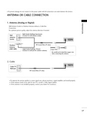
ANTENNA OR CABLECONNECTION 1. mTo prevent damage do not connect to be split for two TV's, install a 2-Way Signal Splitter. m If the antenna needs to the power outlet until all connections are made between the devices. Antenna (Analog or Digital) -O _o... socket) Antenna Socket Outdoor Antenna (VHF, UHF) RF Coaxial Wire (75 ohm) Single-family Dwellings/Houses (Connect to wall jack for assistance. 17 Cable Cable TV Wall Jack m To improve the picture quality in a poor signal area, please purchase a signal amplifier and install properly. m If the antenna is not installed properly...
ANTENNA OR CABLECONNECTION 1. mTo prevent damage do not connect to be split for two TV's, install a 2-Way Signal Splitter. m If the antenna needs to the power outlet until all connections are made between the devices. Antenna (Analog or Digital) -O _o... socket) Antenna Socket Outdoor Antenna (VHF, UHF) RF Coaxial Wire (75 ohm) Single-family Dwellings/Houses (Connect to wall jack for assistance. 17 Cable Cable TV Wall Jack m To improve the picture quality in a poor signal area, please purchase a signal amplifier and install properly. m If the antenna is not installed properly...
Owners Manual
Page 18
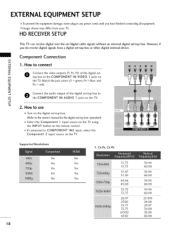
...set -top box or other digital external device. operation) 0_Select the Component 1 input source on the TV using the INPUT button on the remote control. 01I_f connected to the COMPONENT IN VIDEO 1 jacks on x:) C the TV. Match the jack colors (Y = green, PB = blue, and PR = red). EXTERNAL EQUIPMENT ... damage, never plug in any power cords until you do receive digital signals from your TV. lllllIlm_ age shown may differ from a digital set -top box to the COMPONENT IN AUDIO 1 jacks on the TV. However, if you have finished connecting all equipment. z O onnect the audio output ...
...set -top box or other digital external device. operation) 0_Select the Component 1 input source on the TV using the INPUT button on the remote control. 01I_f connected to the COMPONENT IN VIDEO 1 jacks on x:) C the TV. Match the jack colors (Y = green, PB = blue, and PR = red). EXTERNAL EQUIPMENT ... damage, never plug in any power cords until you do receive digital signals from your TV. lllllIlm_ age shown may differ from a digital set -top box to the COMPONENT IN AUDIO 1 jacks on the TV. However, if you have finished connecting all equipment. z O onnect the audio output ...

Owners Manual
Page 19
... to the owner's manual for the digital set-top box.) 01_Select the HDMI1, HDMI2, or HDMI5 _ input source on the TV using the INPUT button on the remote control. * HDMI 3: Except 42/47/52LGSODC HDMI-DTV 31.47 31.50 44.96 45.00 33.72 33.75 26.97 2ZOO 33...
... to the owner's manual for the digital set-top box.) 01_Select the HDMI1, HDMI2, or HDMI5 _ input source on the TV using the INPUT button on the remote control. * HDMI 3: Except 42/47/52LGSODC HDMI-DTV 31.47 31.50 44.96 45.00 33.72 33.75 26.97 2ZOO 33...

Owners Manual
Page 20
m al for the digital set -top box. (Refer to the AUDIO X:) (RGB/DVl) jack on the remote control. * HDMI 3: Except 42/47/52LGSODC 2O How to connect m x m O CthoenHnDeMctI/DVthIe DVI IoNutp1u,t2, ofortSh*ejacdkigointathl eTsVe.t-top box to _o z m O Connect the PC audio output to the owner's manu- How to use z 01T_urn on the digital set -top box.) c "O 01_Select the HDMI1, HDMI2, or HDMI5 _ input source on the TV using the INPUT button on the TV. c "O m 2. EXTERNALEQUIPMENT SETUP DVI to HDMI Connection 1.
m al for the digital set -top box. (Refer to the AUDIO X:) (RGB/DVl) jack on the remote control. * HDMI 3: Except 42/47/52LGSODC 2O How to connect m x m O CthoenHnDeMctI/DVthIe DVI IoNutp1u,t2, ofortSh*ejacdkigointathl eTsVe.t-top box to _o z m O Connect the PC audio output to the owner's manu- How to use z 01T_urn on the digital set -top box.) c "O 01_Select the HDMI1, HDMI2, or HDMI5 _ input source on the TV using the INPUT button on the TV. c "O m 2. EXTERNALEQUIPMENT SETUP DVI to HDMI Connection 1.

Owners Manual
Page 21
... e Connect the audio outputs of the DVD to use Turn on DVD player 21 How to the COMPONENT IN VIDE01 jacks on the TV. 2. Refer to the component input ports as shown below. If connected to the COMPONENT IN AUDIO1 jacks on the... to COMPONENT IN 2 input, select the Component 2 input source on the remote control. Select the Component 1 input source on theTVusing the INPUT button on the TV. DVD SETUP Component Connection 1. Match the jack colors (Y = green, PB = blue, and PR = red). r'rl x r'_ z r'rl c r'_ z r'rl c L--- VIDEO ----J L AUDIO J Component Input...
... e Connect the audio outputs of the DVD to use Turn on DVD player 21 How to the COMPONENT IN VIDE01 jacks on the TV. 2. Refer to the component input ports as shown below. If connected to the COMPONENT IN AUDIO1 jacks on the... to COMPONENT IN 2 input, select the Component 2 input source on the remote control. Select the Component 1 input source on theTVusing the INPUT button on the TV. DVD SETUP Component Connection 1. Match the jack colors (Y = green, PB = blue, and PR = red). r'rl x r'_ z r'rl c r'_ z r'rl c L--- VIDEO ----J L AUDIO J Component Input...


