
Owners Manual
Page 5
... red, green, or blue spots. Do not install in the U.S.A. However, they have been removed. Antenna grounding according to the National Electrical Code, ANSI/NFPA 70 Ground Clamp Electric Service Equipment NEC: National Electrical Code Antenna Lead in Wire Antenna Discharge Unit (NEC Section 810-20) Grounding Conductor (NEC Section 810-21) Ground Clamps Power Service Grounding Electrode System (NEC Art 250, Part...
... red, green, or blue spots. Do not install in the U.S.A. However, they have been removed. Antenna grounding according to the National Electrical Code, ANSI/NFPA 70 Ground Clamp Electric Service Equipment NEC: National Electrical Code Antenna Lead in Wire Antenna Discharge Unit (NEC Section 810-20) Grounding Conductor (NEC Section 810-21) Ground Clamps Power Service Grounding Electrode System (NEC Art 250, Part...

Owners Manual
Page 6
... Installation 19 EXTERNAL EQUIPMENT SETUP HD Receiver Setup 20 DVD Setup 23 VCR Setup 24 Other A/V Source Setup 25 Audio Out Connection 25 PC Setup 26 WATCHING TV / CHANNEL CONTROL Remote Control Functions 32 Turning On TV 34 Channel Selection 34 Volume Adjustment 34 On-Screen Menus Selection 35 Channel Setup - Channel Editing 38 Channel Label 38 Input List 39 Example Electronic Program Guide 40 USB Entry Modes 41 Photo List 43 6 Music List 47 Extra contents 49 PICTURE CONTROL PIP (Picture-In-Picture 50 Picture Size (Aspect Ratio) Control 52 Preset Picture Settings...
... Installation 19 EXTERNAL EQUIPMENT SETUP HD Receiver Setup 20 DVD Setup 23 VCR Setup 24 Other A/V Source Setup 25 Audio Out Connection 25 PC Setup 26 WATCHING TV / CHANNEL CONTROL Remote Control Functions 32 Turning On TV 34 Channel Selection 34 Volume Adjustment 34 On-Screen Menus Selection 35 Channel Setup - Channel Editing 38 Channel Label 38 Input List 39 Example Electronic Program Guide 40 USB Entry Modes 41 Photo List 43 6 Music List 47 Extra contents 49 PICTURE CONTROL PIP (Picture-In-Picture 50 Picture Size (Aspect Ratio) Control 52 Preset Picture Settings...

Owners Manual
Page 11
...power. 8 OPTICAL DIGITAL AUDIO OUT 17 USB IN Optical digital audio output for use with external speakers. 10 REMOTE CONTROL OUT IR output for audio. 13 RJP INTERFACE (REMOTE JACK PACK PORT) Connect this port doesn't work. Uses a D-sub 15 pin cable (VGA cable). 11 AV (Audio/Video) IN 1/2 Analog composite connection. Uses a red, green, and blue cable for video & a red and white cable for controlling an auxiliary device. 2 RGB (PC) Analog PC Connection. Supports HD video and Digital audio. LINK CFG Computer input for programming Free To Guest services. 6 GAME CONTROL Input port...
...power. 8 OPTICAL DIGITAL AUDIO OUT 17 USB IN Optical digital audio output for use with external speakers. 10 REMOTE CONTROL OUT IR output for audio. 13 RJP INTERFACE (REMOTE JACK PACK PORT) Connect this port doesn't work. Uses a D-sub 15 pin cable (VGA cable). 11 AV (Audio/Video) IN 1/2 Analog composite connection. Uses a red, green, and blue cable for video & a red and white cable for controlling an auxiliary device. 2 RGB (PC) Analog PC Connection. Supports HD video and Digital audio. LINK CFG Computer input for programming Free To Guest services. 6 GAME CONTROL Input port...

Owners Manual
Page 20
... receive Digital Over-the-air or Digital Cable signals without an external digital set -top box or other digital external device, refer to the COMPONENT IN VIDEO jacks on the TV. Match the jack colors (Y = green, PB = blue, and PR = red). 2 Connect the audio output of the digital settop box to the figure as shown below. How to use I Turn on the digital set-top box. (Refer to the owner's manual for the digital set -top box to connect Y PB PR L R 1 Connect the video outputs...
... receive Digital Over-the-air or Digital Cable signals without an external digital set -top box or other digital external device, refer to the COMPONENT IN VIDEO jacks on the TV. Match the jack colors (Y = green, PB = blue, and PR = red). 2 Connect the audio output of the digital settop box to the figure as shown below. How to use I Turn on the digital set-top box. (Refer to the owner's manual for the digital set -top box to connect Y PB PR L R 1 Connect the video outputs...

Owners Manual
Page 21
... 60.00 21 If the HDMI cables don't support HDMI version 1.3, it can cause flickers or no screen display. HDMI/DVI IN 2 1(DVI) RGB 2 No separate audio connection is necessary. How to use the latest cables that support HDMI version 1.3. G HDMI mode supports PCM, Dolby Digital audio format. How to connect 1 Connect the digital set-top box to the owner's manual for the digital set-top box.) I Turn on the digital set-top box. (Refer to HDMI/DVI IN 1 (DVI) or 2 jack on the remote control. !
... 60.00 21 If the HDMI cables don't support HDMI version 1.3, it can cause flickers or no screen display. HDMI/DVI IN 2 1(DVI) RGB 2 No separate audio connection is necessary. How to use the latest cables that support HDMI version 1.3. G HDMI mode supports PCM, Dolby Digital audio format. How to connect 1 Connect the digital set-top box to the owner's manual for the digital set-top box.) I Turn on the digital set-top box. (Refer to HDMI/DVI IN 1 (DVI) or 2 jack on the remote control. !

Owners Manual
Page 22
... TV. 2 Connect the audio output of the digital set-top box to the owner's manual for this connection. How to use I Turn on the digital set -top box.) I Select the HDMI1 input source on the TV using the INPUT button on the TV. 2. HDMI/DVI IN 2 1(DVI) RJP INTERFACE 1 TV-LINK CFG G CO LAN (SERVICE ONLY) RESET RGB(PC) UPDA R (S AUDIO (RGB/DVI) RGB IN VIDEO AUDIO COMPONENT IN 2 ! EXTERNAL EQUIPMENT SETUP EXTERNAL EQUIPMENT SETUP DVI to HDMI cable or adapter is necessary...
... TV. 2 Connect the audio output of the digital set-top box to the owner's manual for this connection. How to use I Turn on the digital set -top box.) I Select the HDMI1 input source on the TV using the INPUT button on the TV. 2. HDMI/DVI IN 2 1(DVI) RJP INTERFACE 1 TV-LINK CFG G CO LAN (SERVICE ONLY) RESET RGB(PC) UPDA R (S AUDIO (RGB/DVI) RGB IN VIDEO AUDIO COMPONENT IN 2 ! EXTERNAL EQUIPMENT SETUP EXTERNAL EQUIPMENT SETUP DVI to HDMI cable or adapter is necessary...

Owners Manual
Page 23
... I Turn on the remote control. I Refer to the COMPONENT IN VIDEO jacks on the TV. HDMI OUTPUT 23 How to connect Y PB PR Y B-Y R-Y Y Cb Cr Y Pb Pr 1 Connect the HDMI output of the DVD to the DVD player's manual for operating instructions. HDMI/DVI IN 2 1(DVI) RJP INTERFACE 1 RGB IN (S VIDEO COM 2. VIDEO AAUUDDIIOO / CCOOMMPPOONNEENNTTININ I Select the Component input source on the TV using the INPUT button on the DVD player, insert a DVD. HDMI supports both audio and video. Component Input ports To get better picture quality, connect a DVD player...
... I Turn on the remote control. I Refer to the COMPONENT IN VIDEO jacks on the TV. HDMI OUTPUT 23 How to connect Y PB PR Y B-Y R-Y Y Cb Cr Y Pb Pr 1 Connect the HDMI output of the DVD to the DVD player's manual for operating instructions. HDMI/DVI IN 2 1(DVI) RJP INTERFACE 1 RGB IN (S VIDEO COM 2. VIDEO AAUUDDIIOO / CCOOMMPPOONNEENNTTININ I Select the Component input source on the TV using the INPUT button on the DVD player, insert a DVD. HDMI supports both audio and video. Component Input ports To get better picture quality, connect a DVD player...
Owners Manual
Page 36
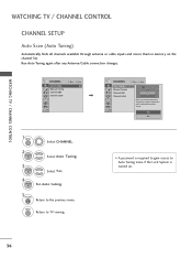
...password is turned on the channel list. CHANNEL Auto Tuning Manual Tuning Channel Edit Channel Label Move Enter CHANNEL Auto Tuning Manual Tuning Channel Edit Channel Label Move Enter Check your antenna connection. The previous channel information will be updated during Auto Tuning. WATCHING TV / CHANNEL CONTROL WATCHING TV / CHANNEL CONTROL CHANNEL SETUP Auto Scan (Auto Tuning) Automatically finds all channels available through antenna or cable inputs and stores them in memory on . 36 MENU Return to TV viewing. Run Auto Tuning again after any Antenna/Cable connection changes...
...password is turned on the channel list. CHANNEL Auto Tuning Manual Tuning Channel Edit Channel Label Move Enter CHANNEL Auto Tuning Manual Tuning Channel Edit Channel Label Move Enter Check your antenna connection. The previous channel information will be updated during Auto Tuning. WATCHING TV / CHANNEL CONTROL WATCHING TV / CHANNEL CONTROL CHANNEL SETUP Auto Scan (Auto Tuning) Automatically finds all channels available through antenna or cable inputs and stores them in memory on . 36 MENU Return to TV viewing. Run Auto Tuning again after any Antenna/Cable connection changes...

Owners Manual
Page 79
...) I TV-Y7 (Children 7 years older) PARENTAL CONTROL / RATING 79 The default setting is also possible to block all programs to be viewed. Enable the lock V-Chip rating and categories Rating guidelines are provided by the broadcasting station. The Parental Control Function (V-Chip) is used to block specific channels, ratings and other viewing sources. PARENTAL CONTROL / RATINGS Parental Control can be used to block program viewing based on the ratings sent by broadcasting...
...) I TV-Y7 (Children 7 years older) PARENTAL CONTROL / RATING 79 The default setting is also possible to block all programs to be viewed. Enable the lock V-Chip rating and categories Rating guidelines are provided by the broadcasting station. The Parental Control Function (V-Chip) is used to block specific channels, ratings and other viewing sources. PARENTAL CONTROL / RATINGS Parental Control can be used to block program viewing based on the ratings sent by broadcasting...

Owners Manual
Page 90
..., reset TV to IR remote key presses. I After TV setup, remove the AC power cord for these offerings are provided by the lodge. Important! If enough time has not elapsed for PPV (Pay-per-view) Operation A PPV card usually has a channel lineup included with the master TV setup. If this is connected to the hotel guest, assuming that they become available..... I Gaming Services. menus...
..., reset TV to IR remote key presses. I After TV setup, remove the AC power cord for these offerings are provided by the lodge. Important! If enough time has not elapsed for PPV (Pay-per-view) Operation A PPV card usually has a channel lineup included with the master TV setup. If this is connected to the hotel guest, assuming that they become available..... I Gaming Services. menus...
Owners Manual
Page 91
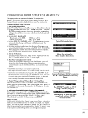
... lock the channel scan. Note: Physical channel numbers are available. 4. AddCustomChannelLabelsforAnalogChannels:2-5-4+MenuMode Enter Installer menu, press 2-5-4 and MENU. Note 1: Disconnect all available channels.) Go to 001 and press ENTER on the remote. Commercial Mode Setup Procedure 1. Set Installer menu item 117 FACT DEFAULT, to the Channel menu and access the Auto Tuning option, follow onscreen instructions. After all installer menu custom settings, channel labels / icons etc. Set Up TV Features (Channel, Picture, Audio, Lock, Time, Option, Digital Captions...
... lock the channel scan. Note: Physical channel numbers are available. 4. AddCustomChannelLabelsforAnalogChannels:2-5-4+MenuMode Enter Installer menu, press 2-5-4 and MENU. Note 1: Disconnect all available channels.) Go to 001 and press ENTER on the remote. Commercial Mode Setup Procedure 1. Set Installer menu item 117 FACT DEFAULT, to the Channel menu and access the Auto Tuning option, follow onscreen instructions. After all installer menu custom settings, channel labels / icons etc. Set Up TV Features (Channel, Picture, Audio, Lock, Time, Option, Digital Captions...
Owners Manual
Page 95
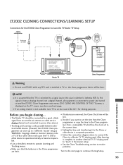
... follow on screen instructions Status Indicator MPI Color Reset • green battery ok • red battery low Blink pattern • slow power on no communications • heartbeat power on the TV screen, see above .) I Setting the time and transferring it the master setup. Master TV Ferrite Core (TDK, ZCAT 2035-0930) Connect cable to continue Cloning Setup. 95 I Teaching and Learning is a separate procedure. G If an analog channel is...
... follow on screen instructions Status Indicator MPI Color Reset • green battery ok • red battery low Blink pattern • slow power on no communications • heartbeat power on the TV screen, see above .) I Setting the time and transferring it the master setup. Master TV Ferrite Core (TDK, ZCAT 2035-0930) Connect cable to continue Cloning Setup. 95 I Teaching and Learning is a separate procedure. G If an analog channel is...
Owners Manual
Page 99
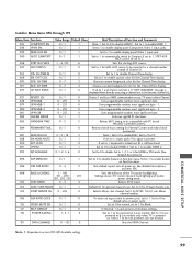
... EN. 0 / 1 1 Note 1. Set 0 for physical channel scan. timing to 1 and loss of all above 101 control dynamic back lighting and enable power saving mode. Set to 1 to enable HDMI 1. 038 YPrPb EN. 0 / 1 1 Set to 1 to enable display panel Component Video 1 input jacks. 039 REAR AUX EN 0 / 1 1 Set to 1 to enable display panel Video 1 input jack. 040 AUTO CAMPORT 0 / 1 1 046 STRT AUX SRCE 1 ~ 6, 255 6 Set to 1 to automatically switch to disable HDMI 2. Sets the starting AUX source. 047 AUX STATUS...
... EN. 0 / 1 1 Note 1. Set 0 for physical channel scan. timing to 1 and loss of all above 101 control dynamic back lighting and enable power saving mode. Set to 1 to enable HDMI 1. 038 YPrPb EN. 0 / 1 1 Set to 1 to enable display panel Component Video 1 input jacks. 039 REAR AUX EN 0 / 1 1 Set to 1 to enable display panel Video 1 input jack. 040 AUTO CAMPORT 0 / 1 1 046 STRT AUX SRCE 1 ~ 6, 255 6 Set to 1 to automatically switch to disable HDMI 2. Sets the starting AUX source. 047 AUX STATUS...
Owners Manual
Page 101
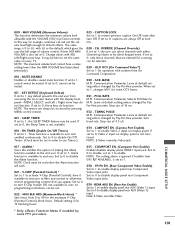
... 4.3 uS. 034 - When set to disable, set at default setting unless changed by Pay-Per-View provider. Communication Parameter. TIMING PULSE M.P.I . Step size of volume control, if item 008 MIN VOLUME is for 12 blocking hours. 035 - Set to 0 to enable display panel rear Component Video input jacks. COMPPORT EN. (Computer Port Enable) Enable/disables display panel HDMI1 input jack. Set to 0 to 1, sound cannot be muted. 011 - Note: S-Video overrides Video. * Only affects Function Menu if enabled by...
... 4.3 uS. 034 - When set to disable, set at default setting unless changed by Pay-Per-View provider. Communication Parameter. TIMING PULSE M.P.I . Step size of volume control, if item 008 MIN VOLUME is for 12 blocking hours. 035 - Set to 0 to enable display panel rear Component Video input jacks. COMPPORT EN. (Computer Port Enable) Enable/disables display panel HDMI1 input jack. Set to 0 to 1, sound cannot be muted. 011 - Note: S-Video overrides Video. * Only affects Function Menu if enabled by...
Owners Manual
Page 102
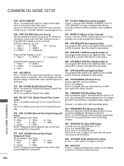
... STATUS Set to be compatible with power cord removal and reinsertion. 088 - AUX source to 1 for Auto Configure one time only with PC based Windows controlled systems, range is set at 1: 2 = Video 2 5 = HDMI 2 6 = Component 075 - DIS. FOR. CH-TIME (Channel-Time Display Background Color) Set according to end user. command. SPI is locked out, not available to Color Chart. 0 = Black 3 = Yellow 6 = Cyan 1 = Red 4 = Blue 7 = White 2 = Green 5 = Violet NOTE: If foreground and background color are the same, menu background is...
... STATUS Set to be compatible with power cord removal and reinsertion. 088 - AUX source to 1 for Auto Configure one time only with PC based Windows controlled systems, range is set at 1: 2 = Video 2 5 = HDMI 2 6 = Component 075 - DIS. FOR. CH-TIME (Channel-Time Display Background Color) Set according to end user. command. SPI is locked out, not available to Color Chart. 0 = Black 3 = Yellow 6 = Cyan 1 = Red 4 = Blue 7 = White 2 = Green 5 = Violet NOTE: If foreground and background color are the same, menu background is...
Owners Manual
Page 103
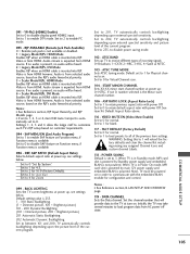
... DEFAULT (Factory Default) Set to disable power saving mode. 102 - RJP AVAILABLE (Remote Jack Pack Available) 0 = Remote jack pack is not available or disabled. 1 = Legacy Model RJPs: HDMI Mode Enables RJP when an HDMI cable is from HDMI however, Audio is inserted into RJP. Audio stream is the Minor start channel number at turn on Function menu, if Function menu is inserted into RJP. ASP. Set to 255, to 0 for Virtual Channel scan. 104 - START MINOR CHANNEL Sets...
... DEFAULT (Factory Default) Set to disable power saving mode. 102 - RJP AVAILABLE (Remote Jack Pack Available) 0 = Remote jack pack is not available or disabled. 1 = Legacy Model RJPs: HDMI Mode Enables RJP when an HDMI cable is from HDMI however, Audio is inserted into RJP. Audio stream is the Minor start channel number at turn on Function menu, if Function menu is inserted into RJP. ASP. Set to 255, to 0 for Virtual Channel scan. 104 - START MINOR CHANNEL Sets...

Owners Manual
Page 104
... manual. After verifying master setup, enter the TV Installer menu and set the Installer menu items to the one shown in the Channel Menu. If necessary, familiarize yourself with that the TV channel memory will also need to 000. Cloning is only possible when the signal source is being performed, specific steps need an LG Installer remote control similar to the configuration required of your institution. With menu displayed, press 2-5-4 + MENU. Changing/Adding Channel...
... manual. After verifying master setup, enter the TV Installer menu and set the Installer menu items to the one shown in the Channel Menu. If necessary, familiarize yourself with that the TV channel memory will also need to 000. Cloning is only possible when the signal source is being performed, specific steps need an LG Installer remote control similar to the configuration required of your institution. With menu displayed, press 2-5-4 + MENU. Changing/Adding Channel...

Owners Manual
Page 116
...HDMI or USB PC Mode Problems I Check the input source. I Check HDMI cable over version 2.0. *This feature is out of the speakers Unusual sound from inside the product I Are the audio cables installed properly? or single color I See troubleshooting flow chart. Power No Power I Update video card drivers. The problem may result in TV controller will appear. Erratic Operation Installer menu setup I Press the VOL or VOLUME button. APPENDIX 116 APPENDIX Audio Problems Picture OK but No sound I Adjust Installer menu settings as required. I Check the signal...
...HDMI or USB PC Mode Problems I Check the input source. I Check HDMI cable over version 2.0. *This feature is out of the speakers Unusual sound from inside the product I Are the audio cables installed properly? or single color I See troubleshooting flow chart. Power No Power I Update video card drivers. The problem may result in TV controller will appear. Erratic Operation Installer menu setup I Press the VOL or VOLUME button. APPENDIX 116 APPENDIX Audio Problems Picture OK but No sound I Adjust Installer menu settings as required. I Check the signal...

Owners Manual
Page 120
... through using CH (Channel) Up/Down. Refers to the input jack that produces video or sound (VCR, DVD, cable box, or television). CABLE Cable service box. INPUT Refers to a tuner device that are transmitted digitally. A/V DEVICE Any device that receives a signal from the list that connects a two-wire 300 ohm antenna to audio in 4:3 picture aspect ratio. HDMI High-definition multi-media interface. HDTV High-definition television. RGB (Red, Green, Blue) Connection input or output port available for producing a video image using an antenna. A/V cables are...
... through using CH (Channel) Up/Down. Refers to the input jack that produces video or sound (VCR, DVD, cable box, or television). CABLE Cable service box. INPUT Refers to a tuner device that are transmitted digitally. A/V DEVICE Any device that receives a signal from the list that connects a two-wire 300 ohm antenna to audio in 4:3 picture aspect ratio. HDMI High-definition multi-media interface. HDTV High-definition television. RGB (Red, Green, Blue) Connection input or output port available for producing a video image using an antenna. A/V cables are...
Owners Manual
Page 123
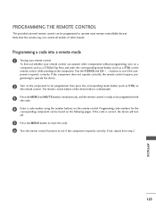
... a code number using the number buttons on the remote control. If not, repeat from step 2. Note that the remote may not control all models of the desired device is illuminated. 3 Press the MENU and MUTE buttons simultaneously, and the remote control is correct, the device will turn on a component such as a STB(Set-Top Box) and press the corresponding mode button (such as S T B) on the remote control. APPENDIX 123 Programming a code into a remote mode 1 Testing your remote control...
... a code number using the number buttons on the remote control. If not, repeat from step 2. Note that the remote may not control all models of the desired device is illuminated. 3 Press the MENU and MUTE buttons simultaneously, and the remote control is correct, the device will turn on a component such as a STB(Set-Top Box) and press the corresponding mode button (such as S T B) on the remote control. APPENDIX 123 Programming a code into a remote mode 1 Testing your remote control...


