

Owner's Manual
Page 1
...* 52LF6* 37LF7* 42LF7* 37LY9* 42LY9* 47LY9* 52LY9* PLASMA TV MODELS 50PF9* 60PF9* Please read this information to 1996) ID Number(s): 4560: 37LY95 4534: 42LY95 4558: 47LY95 4537: 42LF65 4605: 42LY96 4607: 52LY96 4609: 42LF66 4611: 52LF65 4725: 42LF75 4615: 60PF96 4551: 60PF95 4535: 37LF65 4536: 47LF65 4604: 37LY96 4606: 47LY96 4608: 37LF66...
...* 52LF6* 37LF7* 42LF7* 37LY9* 42LY9* 47LY9* 52LY9* PLASMA TV MODELS 50PF9* 60PF9* Please read this information to 1996) ID Number(s): 4560: 37LY95 4534: 42LY95 4558: 47LY95 4537: 42LF65 4605: 42LY96 4607: 52LY96 4609: 42LF66 4611: 52LF65 4725: 42LF75 4615: 60PF96 4551: 60PF95 4535: 37LF65 4536: 47LF65 4604: 37LY96 4606: 47LY96 4608: 37LF66...
Owner's Manual
Page 3
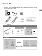
...for all models. 2- ACCESSORIES ACCESSORIES Ensure that excessive power may cause scratch or discoloration. Owner's Manual Owner's manual Owner's Manual D/A I/II MENU TV GUIDE DVD SLEEP INFO i RATIO BACK TEXT PICTURE POWER VCR SUBTITTLVE/RADIO INPUT SOUND EXIT OK VOL 1 MUTE Q.VIEW 4 PR 2 7 LIST 5... 60PF9* only I This feature is stain or fingerprint on surface of that the following accessories are included with your TV. TV Brackets Two rubber caps 2- Do not wipe roughly when removing stain. Polishing Cloth Polish the screen with the cleansing cloths...
...for all models. 2- ACCESSORIES ACCESSORIES Ensure that excessive power may cause scratch or discoloration. Owner's Manual Owner's manual Owner's Manual D/A I/II MENU TV GUIDE DVD SLEEP INFO i RATIO BACK TEXT PICTURE POWER VCR SUBTITTLVE/RADIO INPUT SOUND EXIT OK VOL 1 MUTE Q.VIEW 4 PR 2 7 LIST 5... 60PF9* only I This feature is stain or fingerprint on surface of that the following accessories are included with your TV. TV Brackets Two rubber caps 2- Do not wipe roughly when removing stain. Polishing Cloth Polish the screen with the cleansing cloths...

Owner's Manual
Page 4
...ACCESSORIES 1 PREPARATION Front Panel Controls 4 Back Panel Information 7 Stand installation 10 ATTACHING THE TV TO A DESK 10 Attaching the TV to a wall 11 Back Cover for PC Mode 30 WATCHING TV / PROGRAMME CONTROL Remote Control Key Functions 34 Turning on /off EPG 58 - Screen ...function in date change mode 59 - User option 66 XD - Button function in 8 days guide mode 59 - Picture Mode-Preset 63 - Switch on the TV 38 Programme Selection 39 Volume Adjustment 39 On Screen Menus Selection and Adjustment . . . . 40 Auto Programme Tuning (In Digital Mode) . . . ....
...ACCESSORIES 1 PREPARATION Front Panel Controls 4 Back Panel Information 7 Stand installation 10 ATTACHING THE TV TO A DESK 10 Attaching the TV to a wall 11 Back Cover for PC Mode 30 WATCHING TV / PROGRAMME CONTROL Remote Control Key Functions 34 Turning on /off EPG 58 - Screen ...function in date change mode 59 - User option 66 XD - Button function in 8 days guide mode 59 - Picture Mode-Preset 63 - Switch on the TV 38 Programme Selection 39 Volume Adjustment 39 On Screen Menus Selection and Adjustment . . . . 40 Auto Programme Tuning (In Digital Mode) . . . ....

Owner's Manual
Page 5
CONTENTS SOUND & LANGUAGE CONTROL Auto Volume Leveler 74 Preset Sound Settings - User Mode 76 Balance 77 TV Speakers On/ Off Setup 78 Selecting digital audio out 79 I/II - NICAM Reception (In Analogue Mode Only 81 - Sound Mode 75 Sound Setting Adjustment - Stereo/...
CONTENTS SOUND & LANGUAGE CONTROL Auto Volume Leveler 74 Preset Sound Settings - User Mode 76 Balance 77 TV Speakers On/ Off Setup 78 Selecting digital audio out 79 I/II - NICAM Reception (In Analogue Mode Only 81 - Sound Mode 75 Sound Setting Adjustment - Stereo/...

Owner's Manual
Page 6
... OK VOL PR INPUT MENU OK VOL PR Power/Standby Indicator • illuminates red in standby mode. And when stand be somewhat different from your TV. A If your viewing position. ! PREPARATION FRONT PANEL CONTROLS A This is a simplified representation of stand's back. NOTE G Before adjusting the angle, you must... right direction by 20 degrees to the left ) the shaft bolt on the middle of the front panel. Here shown may be level with TV, you must close (to the right) the shaft bolt to set manually to suit your product has a protection film attached, remove the film...
... OK VOL PR INPUT MENU OK VOL PR Power/Standby Indicator • illuminates red in standby mode. And when stand be somewhat different from your TV. A If your viewing position. ! PREPARATION FRONT PANEL CONTROLS A This is a simplified representation of stand's back. NOTE G Before adjusting the angle, you must... right direction by 20 degrees to the left ) the shaft bolt on the middle of the front panel. Here shown may be level with TV, you must close (to the right) the shaft bolt to set manually to suit your product has a protection film attached, remove the film...

Owner's Manual
Page 7
Power/Standby Indicator • illuminates red in standby mode. PREPARATION LCD TV Models: 37LF6*, 42LF6*, 47LF6*, 52LF6* PR VOL OK MENU INPUT /I PROGRAMME Buttons VOLUME Buttons OK Button MENU Button INPUT Button POWER Button Intelligent Eye Adjusts picture according to the surrounding conditions. Remote Control Sensor • illuminates green when the set is switched on. 5
Power/Standby Indicator • illuminates red in standby mode. PREPARATION LCD TV Models: 37LF6*, 42LF6*, 47LF6*, 52LF6* PR VOL OK MENU INPUT /I PROGRAMME Buttons VOLUME Buttons OK Button MENU Button INPUT Button POWER Button Intelligent Eye Adjusts picture according to the surrounding conditions. Remote Control Sensor • illuminates green when the set is switched on. 5

Owner's Manual
Page 8
... • illuminates red in standby mode. • illuminates green when the set is switched on . 6 PREPARATION LCD TV Models: 37LY9*, 42LY9*, 47LY9*, 52LY9* PREPARATION Intelligent Eye Adjusts picture according to the surrounding conditions. LCD TV Models: 37/42LF7* VOL PR CH PROGRAM Buttons CH VOL VOLUME Buttons VOL OK Button MENU Button...
... • illuminates red in standby mode. • illuminates green when the set is switched on . 6 PREPARATION LCD TV Models: 37LY9*, 42LY9*, 47LY9*, 52LY9* PREPARATION Intelligent Eye Adjusts picture according to the surrounding conditions. LCD TV Models: 37/42LF7* VOL PR CH PROGRAM Buttons CH VOL VOLUME Buttons VOL OK Button MENU Button...

Owner's Manual
Page 9
... to the RS-232C port on the Specifications page. The voltage is not available in all countries.) 2 HDMI Input Connect a HDMI signal to operate the TV on an AC power. Never attempt to HDMI IN. Or DVI(VIDEO)signal to HDMI/DVI port with DVI to HDMI cable. 3 RGB/DVI Audio... Input Connect the monitor output from various types of the back panel. Plasma TV Models VIDEO L/MONO AUDIO R VIDEO L/MONO AUDIO R S-VIDEO AV IN 3 S-VIDEO AV IN 3 S-Video Input Connect S-Video out from your...
... to the RS-232C port on the Specifications page. The voltage is not available in all countries.) 2 HDMI Input Connect a HDMI signal to operate the TV on an AC power. Never attempt to HDMI IN. Or DVI(VIDEO)signal to HDMI/DVI port with DVI to HDMI cable. 3 RGB/DVI Audio... Input Connect the monitor output from various types of the back panel. Plasma TV Models VIDEO L/MONO AUDIO R VIDEO L/MONO AUDIO R S-VIDEO AV IN 3 S-VIDEO AV IN 3 S-Video Input Connect S-Video out from your...

Owner's Manual
Page 10
...power. The voltage is not available in all countries.) 2 HDMI Input Connect a HDMI signal to HDMI IN. Never attempt to operate the TV on the Specifications page. VIDEO AUDIO COMPONENT IN 4 67 3 8 1 PCMCIA (Personal Computer Memory Card International Association) Card Slot (This ...feature is indicated on DC power. 8 PREPARATION S-VIDEO VIDEO L/MONO AUDIO R LCD TV Models (Except 37/42LF7*) ANTENNA IN PREPARATION AV 3 1 2 3 PCMCIA CARD SLOT EJECT HDMI/DVI IN 1 HDMI IN 2 RGB IN RGB(PC) AUDIO...
...power. The voltage is not available in all countries.) 2 HDMI Input Connect a HDMI signal to HDMI IN. Never attempt to operate the TV on the Specifications page. VIDEO AUDIO COMPONENT IN 4 67 3 8 1 PCMCIA (Personal Computer Memory Card International Association) Card Slot (This ...feature is indicated on DC power. 8 PREPARATION S-VIDEO VIDEO L/MONO AUDIO R LCD TV Models (Except 37/42LF7*) ANTENNA IN PREPARATION AV 3 1 2 3 PCMCIA CARD SLOT EJECT HDMI/DVI IN 1 HDMI IN 2 RGB IN RGB(PC) AUDIO...

Owner's Manual
Page 11
... an SVIDEO device. Or DVI(VIDEO)signal to HDMI/DVI port with DVI to these jacks. 9 Power Cord Socket This TV operates on an AC power. Never attempt to operate the TV on DC power. 5 RS-232C IN (CONTROL & SERVICE) PORT Connect to HDMI IN. AV IN 3 AV IN 2 AV IN... COMPONENT IN VIDEO AUDIO 4 56 7 8 1 PCMCIA (Personal Computer Memory Card International Association) Card Slot (This feature is indicated on a PC. 9 PREPARATION LCD TV Models : 37/42LF7* VIDEO L/MONO AUDIO R VIDEO L/MONO AUDIO R USB IN DIGITAL AUDIO OUT VIDEO L/MONO AUDIO R S-VIDEO S-Video Input S-VIDEO Connect ...
... an SVIDEO device. Or DVI(VIDEO)signal to HDMI/DVI port with DVI to these jacks. 9 Power Cord Socket This TV operates on an AC power. Never attempt to operate the TV on DC power. 5 RS-232C IN (CONTROL & SERVICE) PORT Connect to HDMI IN. AV IN 3 AV IN 2 AV IN... COMPONENT IN VIDEO AUDIO 4 56 7 8 1 PCMCIA (Personal Computer Memory Card International Association) Card Slot (This feature is indicated on a PC. 9 PREPARATION LCD TV Models : 37/42LF7* VIDEO L/MONO AUDIO R VIDEO L/MONO AUDIO R USB IN DIGITAL AUDIO OUT VIDEO L/MONO AUDIO R S-VIDEO S-Video Input S-VIDEO Connect ...

Owner's Manual
Page 12
... damage. 2 Assemble the product stand with the product as shown. ATTACHING THE TV TO A DESK (Only 37LF7*) The TV must be pulled in the holes provided. PREPARATION STAND INSTALLATION (Only 37 inch LCD TV Models) 1 Carefully place the product screen side down on a cushioned surface that will protect product and... screen from falling over, the TV should be securely attached to desk so it cannot be attached to the floor/wall per installation instructions. Tipping, shaking, or rocking ...
... damage. 2 Assemble the product stand with the product as shown. ATTACHING THE TV TO A DESK (Only 37LF7*) The TV must be pulled in the holes provided. PREPARATION STAND INSTALLATION (Only 37 inch LCD TV Models) 1 Carefully place the product screen side down on a cushioned surface that will protect product and... screen from falling over, the TV should be securely attached to desk so it cannot be attached to the floor/wall per installation instructions. Tipping, shaking, or rocking ...

Owner's Manual
Page 13
... the product from the product. 1 1 2 or 2 1 Use the eye-bolts or TV brackets/bolts to fix the product to another place undo the ropes first. G Use a ...it up the product, which is a safer way to set up close to tie the product. PREPARATION ATTACHING THE TV TO A WALL I This feature is pulled in the upper holes. 2 Secure the wall brackets with the bolts ...the eye-bolts position before inserting the eye-bolts, loosen the bolts.) * Insert the eye-bolts or TV brackets/bolts and tighten them securely in the forward direction. It will also prevent the product from damage caused...
... the product from the product. 1 1 2 or 2 1 Use the eye-bolts or TV brackets/bolts to fix the product to another place undo the ropes first. G Use a ...it up the product, which is a safer way to set up close to tie the product. PREPARATION ATTACHING THE TV TO A WALL I This feature is pulled in the upper holes. 2 Secure the wall brackets with the bolts ...the eye-bolts position before inserting the eye-bolts, loosen the bolts.) * Insert the eye-bolts or TV brackets/bolts and tighten them securely in the forward direction. It will also prevent the product from damage caused...

Owner's Manual
Page 14
PREPARATION PREPARATION BACK COVER FOR WIRE ARRANGEMENT Plasma TV models 1 Hold the CABLE MANAGEMENT with both hands and pull it as shown. 45° CABLE MANAGEMENT 2 Connect the cables as shown. 12 To connect an additional equipment, see the External equipment Connections section. 3 Reinstall the CABLE MANAGEMENT as necessary.
PREPARATION PREPARATION BACK COVER FOR WIRE ARRANGEMENT Plasma TV models 1 Hold the CABLE MANAGEMENT with both hands and pull it as shown. 45° CABLE MANAGEMENT 2 Connect the cables as shown. 12 To connect an additional equipment, see the External equipment Connections section. 3 Reinstall the CABLE MANAGEMENT as necessary.

Owner's Manual
Page 15
PREPARATION LCD TV models (Except 37/42LF7*) 1 Connect the cables as shown. 3 Bundle the cables using the supplied twister holder. (This feature is dropped, you may be injured or the product may be broken. 13 If the product is not available for all models.) CABLE MANAGEMENT How to remove the cable management Hold the CABLE MANAGEMENT with both hands and pull it upward. ! NOTE G Do not hold the CABLE MANAGEMENT when moving the product. - To connect an additional equipment, see the External equipment Connections section. 2 Install the CABLE MANAGEMENT as necessary.
PREPARATION LCD TV models (Except 37/42LF7*) 1 Connect the cables as shown. 3 Bundle the cables using the supplied twister holder. (This feature is dropped, you may be injured or the product may be broken. 13 If the product is not available for all models.) CABLE MANAGEMENT How to remove the cable management Hold the CABLE MANAGEMENT with both hands and pull it upward. ! NOTE G Do not hold the CABLE MANAGEMENT when moving the product. - To connect an additional equipment, see the External equipment Connections section. 2 Install the CABLE MANAGEMENT as necessary.

Owner's Manual
Page 16
....) ! To connect an additional equipment, see the External equipment Connections section. 2 Install the CABLE MANAGEMENT as shown. (Insert it out as necessary. PREPARATION PREPARATION LCD TV model (Only 37/42LF7*) 1 Connect the cables as holding the loops on the both hands and pull it out. (Pull it as pushing the loops...
....) ! To connect an additional equipment, see the External equipment Connections section. 2 Install the CABLE MANAGEMENT as shown. (Insert it out as necessary. PREPARATION PREPARATION LCD TV model (Only 37/42LF7*) 1 Connect the cables as holding the loops on the both hands and pull it out. (Pull it as pushing the loops...

Owner's Manual
Page 17
... various ways such as on a wall, or on a desktop etc. GROUNDING Ensure that you want to install the desk-type stand fixture protection cover (Plasma TV models only) To prevent the foreign materials from Bolts entering the desk-type stand fixture, fix the desk-type stand fixture protection cover by connecting...
... various ways such as on a wall, or on a desktop etc. GROUNDING Ensure that you want to install the desk-type stand fixture protection cover (Plasma TV models only) To prevent the foreign materials from Bolts entering the desk-type stand fixture, fix the desk-type stand fixture protection cover by connecting...

Owner's Manual
Page 18
... RS-232C IN I In poor signal areas,to get better picture quality, install a signal amplifier to the antenna as shown to be split for two TVs,use an antenna signal splitter for outdoor antenna) - I To prevent the equipment damage, never plug in any power cords until you have finished connecting all...
... RS-232C IN I In poor signal areas,to get better picture quality, install a signal amplifier to the antenna as shown to be split for two TVs,use an antenna signal splitter for outdoor antenna) - I To prevent the equipment damage, never plug in any power cords until you have finished connecting all...

Owner's Manual
Page 19
...-top box.) 1 2 4 Select COMPONENT input source with a component cable 1 Connect the video outputs (Y, PB, PR) of EXTERNAL EQUIPMENT SETUP mainly use pictures for the LCD TV models. EXTERNAL EQUIPMENT SETUP I To prevent the equipment damage, never plug in any power cords until you do receive Digital signals from a digital set-top... IN VIDEO AUDIO 17 When connecting with using the INPUT button on the set -top box.However,if you have finished connecting all equipment. I This TV can receive Digital Over-the-air/Cable signals without an external digital set .
...-top box.) 1 2 4 Select COMPONENT input source with a component cable 1 Connect the video outputs (Y, PB, PR) of EXTERNAL EQUIPMENT SETUP mainly use pictures for the LCD TV models. EXTERNAL EQUIPMENT SETUP I To prevent the equipment damage, never plug in any power cords until you do receive Digital signals from a digital set-top... IN VIDEO AUDIO 17 When connecting with using the INPUT button on the set -top box.However,if you have finished connecting all equipment. I This TV can receive Digital Over-the-air/Cable signals without an external digital set .

Owner's Manual
Page 22
Component ports on the TV Y Y Video output ports Y on the remote control. 1 2 5 Refer to the DVD player's mPaCnMuCaIAl for opEeJrEaCtiTng instructions. CARD SLOT HDMI/DVI IN 1 HDMI IN 2 RGB IN ...
Component ports on the TV Y Y Video output ports Y on the remote control. 1 2 5 Refer to the DVD player's mPaCnMuCaIAl for opEeJrEaCtiTng instructions. CARD SLOT HDMI/DVI IN 1 HDMI IN 2 RGB IN ...

Owner's Manual
Page 24
...RGB/DVI) RGB IN 2 Select HDMI1, HDMI2 or HDMI3 input source with using a HDMI cable. For further information, see p.48. NOTE G TV can receive the video and audio signal simultaneously with using the INPUT button on the set the output resolution appropriately. VIDEO AUDIO 1 COMPONENT IN 3 ... IN 2 HDMI IN 3 AV 1 1 Connect the HDMI output of the DVD to PCMCIA (Personal Computer Memory Card International Association) CARD SLOT of TV as shown. G If the DVD does not support Auto HDMI, you need to the DVD player's manual for operating instructions. PCMCIA CARD SLOT 1...
...RGB/DVI) RGB IN 2 Select HDMI1, HDMI2 or HDMI3 input source with using a HDMI cable. For further information, see p.48. NOTE G TV can receive the video and audio signal simultaneously with using the INPUT button on the set the output resolution appropriately. VIDEO AUDIO 1 COMPONENT IN 3 ... IN 2 HDMI IN 3 AV 1 1 Connect the HDMI output of the DVD to PCMCIA (Personal Computer Memory Card International Association) CARD SLOT of TV as shown. G If the DVD does not support Auto HDMI, you need to the DVD player's manual for operating instructions. PCMCIA CARD SLOT 1...


