
Owners Manual
Page 3
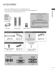
... Q.MENU or OK BACK EXIT ENERGY AV MODE INPUT SAVING 123 456 789 LIST 0 Q.VIEW MARK FAV RATIO MUTE P PA G E MENU Q.MENU OK BACK EXIT Remote Control Polishing Cloth Polishing cloth for use excessive force. If an accessory is not included for stand fixing (Refer to p. 11) 1-screw for all models...
... Q.MENU or OK BACK EXIT ENERGY AV MODE INPUT SAVING 123 456 789 LIST 0 Q.VIEW MARK FAV RATIO MUTE P PA G E MENU Q.MENU OK BACK EXIT Remote Control Polishing Cloth Polishing cloth for use excessive force. If an accessory is not included for stand fixing (Refer to p. 11) 1-screw for all models...

Owners Manual
Page 4
... 6 Stand Installation 9 Attaching the TV to a desk 10 Not Using the desk-type stand 11 Back Cover for PC Mode 28 WATCHING TV / PROGRAMME CONTROL Remote Control Key Functions 32 Turning on the TV 36 Programme Selection 36 Volume Adjustment 36 Quick Menu 37 On-Screen Menus Selection and Adjustment..... 38...
... 6 Stand Installation 9 Attaching the TV to a desk 10 Not Using the desk-type stand 11 Back Cover for PC Mode 28 WATCHING TV / PROGRAMME CONTROL Remote Control Key Functions 32 Turning on the TV 36 Programme Selection 36 Volume Adjustment 36 Quick Menu 37 On-Screen Menus Selection and Adjustment..... 38...
Owners Manual
Page 6
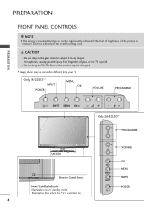
... step on . I Image shown may fall. Only 19/22LD3** INPUT POWER MENU OK VOLUME PROGRAMME PREPARATION INPUT MENUP OK P P Only 26/32LD3** PROGRAMME P VOLUME SPEAKER Remote Control Sensor Power/Standby Indicator • Illuminates red in standby mode. • Illuminates blue when the TV is reduced, and this will reduce the overall...
... step on . I Image shown may fall. Only 19/22LD3** INPUT POWER MENU OK VOLUME PROGRAMME PREPARATION INPUT MENUP OK P P Only 26/32LD3** PROGRAMME P VOLUME SPEAKER Remote Control Sensor Power/Standby Indicator • Illuminates red in standby mode. • Illuminates blue when the TV is reduced, and this will reduce the overall...
Owners Manual
Page 7
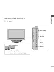
Only 32/42LD4** SPEAKER Remote Control Sensor Power/Standby Indicator • Illuminates red in standby mode. • Illuminates blue when the TV is switched on. P OK MENU INPUT PROGRAMME VOLUME OK MENU INPUT POWER 5 PREPARATION I Image shown may be somewhat different from your TV.
Only 32/42LD4** SPEAKER Remote Control Sensor Power/Standby Indicator • Illuminates red in standby mode. • Illuminates blue when the TV is switched on. P OK MENU INPUT PROGRAMME VOLUME OK MENU INPUT POWER 5 PREPARATION I Image shown may be somewhat different from your TV.

Owners Manual
Page 19
... on the TV. /DVI IN 2 Connect the audio output of the digital set -top box.) 4 Select Component input source using the INPUT button on the remote control. 1 2 Signal 480i / 576i 480p / 576p 720p / 1080i 1080p Component HDMI O X O O O O O O (50 Hz / 60 Hz only) (24 Hz / 30 Hz / 50 Hz / 60 Hz) 17...
... on the TV. /DVI IN 2 Connect the audio output of the digital set -top box.) 4 Select Component input source using the INPUT button on the remote control. 1 2 Signal 480i / 576i 480p / 576p 720p / 1080i 1080p Component HDMI O X O O O O O O (50 Hz / 60 Hz only) (24 Hz / 30 Hz / 50 Hz / 60 Hz) 17...

Owners Manual
Page 20
... -top box to HDMI/DVI IN 1, HDMI/DVI IN 2(Except 19/22LD3**) or HDMI IN 3(Only 32/42LD4**) jack on the TV. 2 Turn on the remote control. ! G We recommed less than that your HDMI cable is High Speed HDMI Cable. AUDIO (RGB/D 2 RGB IN (PC) VIDEO /MONO 1 /DVI IN Y PB PR...
... -top box to HDMI/DVI IN 1, HDMI/DVI IN 2(Except 19/22LD3**) or HDMI IN 3(Only 32/42LD4**) jack on the TV. 2 Turn on the remote control. ! G We recommed less than that your HDMI cable is High Speed HDMI Cable. AUDIO (RGB/D 2 RGB IN (PC) VIDEO /MONO 1 /DVI IN Y PB PR...

Owners Manual
Page 21
AUDIO IN (RGB/DVI) 2 RGB IN (PC) VIDEO /MONO AUD 1 /DVI IN Y PB PR L VIDEO AUDIO COMPONENT IN 1 2 19 EXTERNAL EQUIPMENT SETUP Connecting with an HDMI to DVI cable 1 Connect the digital set-top box to HDMI/DVI IN 1 jack on the TV. 2 Connect the audio output of the digital set-top box to the AUDIO IN (RGB/DVI) jack on the TV. 3 Turn on the digital set-top box. (Refer to the owner's manual for the digital set-top box.) 4 Select HDMI1input source using the INPUT button on the remote control.
AUDIO IN (RGB/DVI) 2 RGB IN (PC) VIDEO /MONO AUD 1 /DVI IN Y PB PR L VIDEO AUDIO COMPONENT IN 1 2 19 EXTERNAL EQUIPMENT SETUP Connecting with an HDMI to DVI cable 1 Connect the digital set-top box to HDMI/DVI IN 1 jack on the TV. 2 Connect the audio output of the digital set-top box to the AUDIO IN (RGB/DVI) jack on the TV. 3 Turn on the digital set-top box. (Refer to the owner's manual for the digital set-top box.) 4 Select HDMI1input source using the INPUT button on the remote control.

Owners Manual
Page 22
... picture quality, connect a DVD player to the DVD player's manual for operating instruc- Component ports on the TV Y PB PR Video output ports on the remote control. 5 Refer to the component input ports as shown below.
... picture quality, connect a DVD player to the DVD player's manual for operating instruc- Component ports on the TV Y PB PR Video output ports on the remote control. 5 Refer to the component input ports as shown below.

Owners Manual
Page 23
... HDMI output of the DVD to the HDMI/DVI IN 1, HDMI/DVI IN 2(Except 19/22LD3**) or HDMI IN 3(Only 32/42LD4**) jack on the remote control. 3 Refer to use the High Speed HDMI Cable. Please use amplifier or repeater for operating instructions.
... HDMI output of the DVD to the HDMI/DVI IN 1, HDMI/DVI IN 2(Except 19/22LD3**) or HDMI IN 3(Only 32/42LD4**) jack on the remote control. 3 Refer to use the High Speed HDMI Cable. Please use amplifier or repeater for operating instructions.

Owners Manual
Page 25
... VCR. Match the jack colours (Video = yellow, Audio Left = white, and Audio Right = red) 2 Insert a video tape into the VCR and press PLAY on the remote control.
... VCR. Match the jack colours (Video = yellow, Audio Left = white, and Audio Right = red) 2 Insert a video tape into the VCR and press PLAY on the remote control.

Owners Manual
Page 26
... equipment. Match the jack colours . (Video = yellow, Audio Left = white, and Audio Right = red) 2 Select AV1 input source with using the INPUT button on the remote control. EXTERNAL EQUIPMENT SETUP OTHER A/V SOURCE SETUP DIO R (RGB/DVI) 1 RGB IN (PC) VIDEO L(MONO) AUDIO R /DVI IN Y PB PR L R ANTENNA VIDEO AUDIO IN COMPONENT...
... equipment. Match the jack colours . (Video = yellow, Audio Left = white, and Audio Right = red) 2 Select AV1 input source with using the INPUT button on the remote control. EXTERNAL EQUIPMENT SETUP OTHER A/V SOURCE SETUP DIO R (RGB/DVI) 1 RGB IN (PC) VIDEO L(MONO) AUDIO R /DVI IN Y PB PR L R ANTENNA VIDEO AUDIO IN COMPONENT...

Owners Manual
Page 28
... the AUDIO IN (RGB/DVI) jack on the TV. 3 Turn on the TV and the PC. 4 Select R G B input source using the INPUT button on the remote control. RS-232C IN (CONTROL) USB IN SERVICE ONLY /DVI IN AUDIO IN (RGB/DVI) RGB IN (PC) VIDEO /MONO AUDIO Y PB PR L R ANT VIDEO...
... the AUDIO IN (RGB/DVI) jack on the TV. 3 Turn on the TV and the PC. 4 Select R G B input source using the INPUT button on the remote control. RS-232C IN (CONTROL) USB IN SERVICE ONLY /DVI IN AUDIO IN (RGB/DVI) RGB IN (PC) VIDEO /MONO AUDIO Y PB PR L R ANT VIDEO...
Owners Manual
Page 34
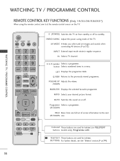
... of the TV. Q.VIEW Returns to 9 number Selects a programme. WATCHING TV / PROGRAMME CONTROL WATCHING TV / PROGRAMME CONTROL REMOTE CONTROL KEY FUNCTIONS (Only 19/22/26/32LD33*) When using the remote control, aim it at the remote control sensor on TELETEXT buttons models only), Programme edit. 1 1 TELETEXT These buttons are used for teletext (on...
... of the TV. Q.VIEW Returns to 9 number Selects a programme. WATCHING TV / PROGRAMME CONTROL WATCHING TV / PROGRAMME CONTROL REMOTE CONTROL KEY FUNCTIONS (Only 19/22/26/32LD33*) When using the remote control, aim it at the remote control sensor on TELETEXT buttons models only), Programme edit. 1 1 TELETEXT These buttons are used for teletext (on...

Owners Manual
Page 36
... KEY FUNCTIONS (Except 19/22/26/32LD33*) When using the remote control, aim it at the remote control sensor on TELETEXT buttons models only), Programme edit. 1 TELETEXT These buttons are used for teletext (on the TV. Q.VIEW Returns to 9 number Selects a programme. ...
... KEY FUNCTIONS (Except 19/22/26/32LD33*) When using the remote control, aim it at the remote control sensor on TELETEXT buttons models only), Programme edit. 1 TELETEXT These buttons are used for teletext (on the TV. Q.VIEW Returns to 9 number Selects a programme. ...

Owners Manual
Page 38
When your TV is turned on, you wish to the image quality set by us after turning on the remote control and the TV will be displayed again. Note: a. If a user modifies image quality data, "Store Demo" mode initializes the product to switch the sound ...
When your TV is turned on, you wish to the image quality set by us after turning on the remote control and the TV will be displayed again. Note: a. If a user modifies image quality data, "Store Demo" mode initializes the product to switch the sound ...

Owners Manual
Page 50
... time, the maximum volume of the SIMPLINK device with the SIMPLINK logo. This TV might not function properly when using the INPUT button on the remote control, you to the previous menu screen. !
... time, the maximum volume of the SIMPLINK device with the SIMPLINK logo. This TV might not function properly when using the INPUT button on the remote control, you to the previous menu screen. !

Owners Manual
Page 52
... to even if you turn the TV off , press the r / I, INPUT, P D or E(or P ) button on the TV or POWER, INPUT, P or NUMBER buttons on the remote control then the set to control it. OPTION Menu Language Input Label SIMPLINK Key Lock Set ID Power Indicator Demo Mode Mode Setting E Move OK...
... to even if you turn the TV off , press the r / I, INPUT, P D or E(or P ) button on the TV or POWER, INPUT, P or NUMBER buttons on the remote control then the set to control it. OPTION Menu Language Input Label SIMPLINK Key Lock Set ID Power Indicator Demo Mode Mode Setting E Move OK...

Owners Manual
Page 57
Images are displayed in the form of marked photos 4 Corresponding buttons on the remote control 1 2 3 PHOTO LIST Drive1 JMJ001 1366x768, 125KB Up Folder Page 2/3 No Marked Up Folder KY101 12/10/2009 KY102 12/10/2009 JMJ001 12/10/...
Images are displayed in the form of marked photos 4 Corresponding buttons on the remote control 1 2 3 PHOTO LIST Drive1 JMJ001 1366x768, 125KB Up Folder Page 2/3 No Marked Up Folder KY101 12/10/2009 KY102 12/10/2009 JMJ001 12/10/...

Owners Manual
Page 61
... may contain copyright restrictions. Playback of marked music title 4 Corresponding buttons on your USB device can be different from your TV. Music file on the remote control 1 2 3 MUSIC LIST Music M002 Page 2/3 No Marked Title Up Folder 00:00 / 1:34 Up Folder M001 M002 M003 M004 Navigation OPTION Page Change 4 Duration...
... may contain copyright restrictions. Playback of marked music title 4 Corresponding buttons on your USB device can be different from your TV. Music file on the remote control 1 2 3 MUSIC LIST Music M002 Page 2/3 No Marked Title Up Folder 00:00 / 1:34 Up Folder M001 M002 M003 M004 Navigation OPTION Page Change 4 Duration...

Owners Manual
Page 63
... displays inappropri- G This TV can use the GG button to select the next music and the FF button to an fixed image remaining on the remote control are also available in playtime.
... displays inappropri- G This TV can use the GG button to select the next music and the FF button to an fixed image remaining on the remote control are also available in playtime.


