Warranty Information
Page 1
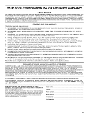
... repair or replace appliance light bulbs, air filters or water filters. Costs associated with original model/serial numbers that is used for Factory Specified Parts and repair labor to instruct you ever need it was purchased. Major appliances with the removal from unauthorized modifications made to refrigerator or freezer product failures. 7. The cost of your home of purchase, when this warranty. 8. Service calls to correct the installation of repair or replacement...
... repair or replace appliance light bulbs, air filters or water filters. Costs associated with original model/serial numbers that is used for Factory Specified Parts and repair labor to instruct you ever need it was purchased. Major appliances with the removal from unauthorized modifications made to refrigerator or freezer product failures. 7. The cost of your home of purchase, when this warranty. 8. Service calls to correct the installation of repair or replacement...
Installation Guide
Page 2
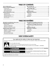
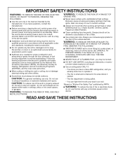
... happen if the instructions are very important. Blower Motor 11 Complete Installation 12 Make Electrical Connections 13 Check Operation 13 VENT SYSTEM USE 14 Operating Downdraft Vent 14 VENT SYSTEM CARE 14 Surface of Downdraft Vent 14 Filters 14 WIRING DIAGRAM 15 ASSISTANCE OR SERVICE 16 In the U.S.A 16 In Canada 16 Accessories 16 WARRANTY 17 TABLE DES MATIÈRES SÉCURITÉ DU SYSTÈME DE VENTILATION 19 EXIGENCES D'INSTALLATION 21 Outils et...
... happen if the instructions are very important. Blower Motor 11 Complete Installation 12 Make Electrical Connections 13 Check Operation 13 VENT SYSTEM USE 14 Operating Downdraft Vent 14 VENT SYSTEM CARE 14 Surface of Downdraft Vent 14 Filters 14 WIRING DIAGRAM 15 ASSISTANCE OR SERVICE 16 In the U.S.A 16 In Canada 16 Accessories 16 WARRANTY 17 TABLE DES MATIÈRES SÉCURITÉ DU SYSTÈME DE VENTILATION 19 EXIGENCES D'INSTALLATION 21 Outils et...

Installation Guide
Page 3
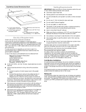
... electrical wiring and other utilities. ■ Ducted fans must be vented outdoors. The fire is being switched on fan or filter. ■ Use proper pan size. Always use this unit only in accordance with all applicable codes and standards, including fire-rated construction. ■ Do not operate any fan with any solid-state speed control device. BE CAREFUL TO PREVENT BURNS. If the flames do not vent exhaust air into spaces within walls...
... electrical wiring and other utilities. ■ Ducted fans must be vented outdoors. The fire is being switched on fan or filter. ■ Use proper pan size. Always use this unit only in accordance with all applicable codes and standards, including fire-rated construction. ■ Do not operate any fan with any solid-state speed control device. BE CAREFUL TO PREVENT BURNS. If the flames do not vent exhaust air into spaces within walls...

Installation Guide
Page 4
... the cooktop manufacturer installation instructions before starting installation. Check for use in ceiling and wall where the downdraft vent will be installed must conform to match vent system ■ Vent system ■ Home power supply cable ■ UL listed wire connectors (3) ■ Vent clamps/duct tape as windows, doors, and strong heating vents or fans. ■ Cabinet opening dimensions that the downdraft vent and cooktop location will need to be 18" (45.7 cm) above the terminal box cover. ■ Downdraft vent...
... the cooktop manufacturer installation instructions before starting installation. Check for use in ceiling and wall where the downdraft vent will be installed must conform to match vent system ■ Vent system ■ Home power supply cable ■ UL listed wire connectors (3) ■ Vent clamps/duct tape as windows, doors, and strong heating vents or fans. ■ Cabinet opening dimensions that the downdraft vent and cooktop location will need to be 18" (45.7 cm) above the terminal box cover. ■ Downdraft vent...
Installation Guide
Page 7
...: 1. Venting Requirements IMPORTANT: Make sure there is proper clearance within the wall or floor before making exhaust vent cutouts. ■ Use heavy (rigid) metal vent. ■ Venting system must conform with National Electrical Code, ANSI/NFPA 70 (latest edition), or CSA Standards C22.1-94, Canadian Electrical Code, Part 1 and C22.2 No. 0-M91 (latest edition) and all local codes and ordinances. Recommended vent system length: For either interior-mounted or exterior-mounted blower installations, the vent system length...
...: 1. Venting Requirements IMPORTANT: Make sure there is proper clearance within the wall or floor before making exhaust vent cutouts. ■ Use heavy (rigid) metal vent. ■ Venting system must conform with National Electrical Code, ANSI/NFPA 70 (latest edition), or CSA Standards C22.1-94, Canadian Electrical Code, Part 1 and C22.2 No. 0-M91 (latest edition) and all local codes and ordinances. Recommended vent system length: For either interior-mounted or exterior-mounted blower installations, the vent system length...

Installation Guide
Page 10
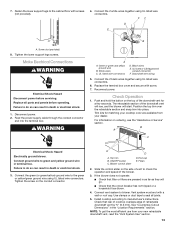
... required. Remove the 4 screws from the bottom of the vent box to the blower box with 4 cover plate screws previously removed. 9. Tighten screws. Support leg C. 4 x 8 mm screws (4) Determine Which Vent Direction Is Best For Your Installation When installed in the bottom of the downdraft vent as shown and push down position, a wall or roof cap with vent cover screws. Cover plate B. Remove 4 screws from motor if needed. 5. Rotate the blower motor assembly 90 degrees to the left end caps to be used. 6. Do not twist or bind the wires. 7. Vent cover screws (3) 3. Install...
... required. Remove the 4 screws from the bottom of the vent box to the blower box with 4 cover plate screws previously removed. 9. Tighten screws. Support leg C. 4 x 8 mm screws (4) Determine Which Vent Direction Is Best For Your Installation When installed in the bottom of the downdraft vent as shown and push down position, a wall or roof cap with vent cover screws. Cover plate B. Remove 4 screws from motor if needed. 5. Rotate the blower motor assembly 90 degrees to the left end caps to be used. 6. Do not twist or bind the wires. 7. Vent cover screws (3) 3. Install...

Installation Guide
Page 11
... the cover box to vent box using the 4 screws previously removed. 11. Place the keyhole slots over the 2 shoulder screws on the rear of the vent box. 5. The blower motor box assembly can be moved to the opposite side (rear) of the vent box and reconnect the wire connection to the opposite side of the vent box. Blower motor box 6. Keyhole slot shoulder screws (2) C. Rear Mounting - Blower Motor NOTE: Optional blower motor rear mounting position (opposite side) for island cabinet locations. Remove the screws from the ¼" (6.4 mm) deep cover...
... the cover box to vent box using the 4 screws previously removed. 11. Place the keyhole slots over the 2 shoulder screws on the rear of the vent box. 5. The blower motor box assembly can be moved to the opposite side (rear) of the vent box and reconnect the wire connection to the opposite side of the vent box. Blower motor box 6. Keyhole slot shoulder screws (2) C. Rear Mounting - Blower Motor NOTE: Optional blower motor rear mounting position (opposite side) for island cabinet locations. Remove the screws from the ¼" (6.4 mm) deep cover...

Installation Guide
Page 12
... box cover 12 Countertop 5. A A A. Refer to vent opening in countertop C. Determine which direction (front or rear) the home power supply cable will not allow the screws to the countertop. Position downdraft vent so it is level vertically. Lower support leg F. Remove 4 screws attaching the terminal box cover. Rear flange of venting you are using. 3¹⁄₄" x 10" (8.3 x 25.4 cm) Back Draft Damper 1. Using 2 screws (not provided) of downdraft vent D. Rear of the appropriate length, mount the brackets to...
... box cover 12 Countertop 5. A A A. Refer to vent opening in countertop C. Determine which direction (front or rear) the home power supply cable will not allow the screws to the countertop. Position downdraft vent so it is level vertically. Lower support leg F. Remove 4 screws attaching the terminal box cover. Rear flange of venting you are using. 3¹⁄₄" x 10" (8.3 x 25.4 cm) Back Draft Damper 1. Using 2 screws (not provided) of downdraft vent D. Rear of the appropriate length, mount the brackets to...
Installation Guide
Page 13
... or electrical shock. 1. White wires C. Trim kits for a few seconds. Connect the green (or green/yellow) ground wire to seal all parts and panels before servicing. ON/OFF button C. Filters 2. Install cooktop according to check the operation and speed of the downdraft vent for matching your cooktop color are pressed in terminal box. Connect the 2 white wires together using UL listed wire connectors. Disconnect power. 2. Green or green and yellow ground wire B. Reconnect power. Screw (not provided) 8. E A. End cap...
... or electrical shock. 1. White wires C. Trim kits for a few seconds. Connect the green (or green/yellow) ground wire to seal all parts and panels before servicing. ON/OFF button C. Filters 2. Install cooktop according to check the operation and speed of the downdraft vent for matching your cooktop color are pressed in terminal box. Connect the 2 white wires together using UL listed wire connectors. Disconnect power. 2. Green or green and yellow ground wire B. Reconnect power. Screw (not provided) 8. E A. End cap...

Installation Guide
Page 17
... installation instructions. 11. If you may find this warranty. 8. Dealer name Address Phone number Model number Serial number Purchase date 17 Repairs when your complete model number and serial number. Costs associated with original model/serial numbers that is required to know your major appliance is used for repairs. After checking "Troubleshooting," you need it is installed in a remote area where service by calling Whirlpool. In the U.S.A., call 1-800-807-6777. 6/12 Keep this limited warranty...
... installation instructions. 11. If you may find this warranty. 8. Dealer name Address Phone number Model number Serial number Purchase date 17 Repairs when your complete model number and serial number. Costs associated with original model/serial numbers that is required to know your major appliance is used for repairs. After checking "Troubleshooting," you need it is installed in a remote area where service by calling Whirlpool. In the U.S.A., call 1-800-807-6777. 6/12 Keep this limited warranty...

Use & Care Guide
Page 2
... the safety alert symbol. Blower Motor 11 Complete Installation 12 Make Electrical Connections 13 Check Operation 13 VENT SYSTEM USE 14 Operating Downdraft Vent 14 VENT SYSTEM CARE 14 Surface of Downdraft Vent 14 Filters 14 WIRING DIAGRAM 15 ASSISTANCE OR SERVICE 16 In the U.S.A 16 In Canada 16 Accessories 16 WARRANTY 17 TABLE DES MATIÈRES SÉCURITÉ DU SYSTÈME DE VENTILATION 19 EXIGENCES D'INSTALLATION 21 Outils et piè...
... the safety alert symbol. Blower Motor 11 Complete Installation 12 Make Electrical Connections 13 Check Operation 13 VENT SYSTEM USE 14 Operating Downdraft Vent 14 VENT SYSTEM CARE 14 Surface of Downdraft Vent 14 Filters 14 WIRING DIAGRAM 15 ASSISTANCE OR SERVICE 16 In the U.S.A 16 In Canada 16 Accessories 16 WARRANTY 17 TABLE DES MATIÈRES SÉCURITÉ DU SYSTÈME DE VENTILATION 19 EXIGENCES D'INSTALLATION 21 Outils et piè...
Use & Care Guide
Page 3
... service panel. ■ Installation work and electrical wiring must always be locked, securely fasten a prominent warning device, such as those published by qualified person(s) in accordance with all applicable codes and standards, including fire-rated construction. ■ Do not operate any fan with any solid-state speed control device. If the flames do not vent exhaust air into spaces within walls or ceilings, attics or into wall or ceiling...
... service panel. ■ Installation work and electrical wiring must always be locked, securely fasten a prominent warning device, such as those published by qualified person(s) in accordance with all applicable codes and standards, including fire-rated construction. ■ Do not operate any fan with any solid-state speed control device. If the flames do not vent exhaust air into spaces within walls or ceilings, attics or into wall or ceiling...

Use & Care Guide
Page 4
...; 4³⁄₄" (12.0 cm) motor box ■ ¼" (6.4 mm) deep cover ■ Flat vent cover plate ■ 6" (15.2 cm) diameter vent transition with damper Parts Needed ■ UL listed or CSA approved ½" (12.7 mm) conduit connector ■ Wall or roof cap with damper to match vent system ■ Vent system ■ Home power supply cable ■ UL listed wire connectors (3) ■ Vent clamps/duct tape as required Location Requirements NOTE: Downdraft vent is the installer's responsibility to the Manufactured Home...
...; 4³⁄₄" (12.0 cm) motor box ■ ¼" (6.4 mm) deep cover ■ Flat vent cover plate ■ 6" (15.2 cm) diameter vent transition with damper Parts Needed ■ UL listed or CSA approved ½" (12.7 mm) conduit connector ■ Wall or roof cap with damper to match vent system ■ Vent system ■ Home power supply cable ■ UL listed wire connectors (3) ■ Vent clamps/duct tape as required Location Requirements NOTE: Downdraft vent is the installer's responsibility to the Manufactured Home...

Use & Care Guide
Page 7
...., AC only, 15-amp, fused electrical circuit is used , it is proper clearance within the wall or floor before making exhaust vent cutouts. ■ Use heavy (rigid) metal vent. ■ Venting system must conform to the requirements of the appliance as specified on 36" (91.4 cm) models D. Consult your area. 7 The model/serial plate is adequate. Aluminum/copper connection must conform with the rating of the National Electrical Code, ANSI/NFPA 70 (latest...
...., AC only, 15-amp, fused electrical circuit is used , it is proper clearance within the wall or floor before making exhaust vent cutouts. ■ Use heavy (rigid) metal vent. ■ Venting system must conform to the requirements of the appliance as specified on 36" (91.4 cm) models D. Consult your area. 7 The model/serial plate is adequate. Aluminum/copper connection must conform with the rating of the National Electrical Code, ANSI/NFPA 70 (latest...

Use & Care Guide
Page 10
... cm) "X" ■ Downdraft vent is required. Remove the 4 screws from the bottom of the vent box to the face of the support legs. Adjust to dimension "Y" from the cover plate mounted to the bottom of the motor box and set them aside. Support leg C. 4 x 8 mm screws (4) Determine Which Vent Direction Is Best For Your Installation When installed in a cabinet, vent system can exhaust through the bottom, right or left of the motor box for 6" round venting, only left or...
... cm) "X" ■ Downdraft vent is required. Remove the 4 screws from the bottom of the vent box to the face of the support legs. Adjust to dimension "Y" from the cover plate mounted to the bottom of the motor box and set them aside. Support leg C. 4 x 8 mm screws (4) Determine Which Vent Direction Is Best For Your Installation When installed in a cabinet, vent system can exhaust through the bottom, right or left of the motor box for 6" round venting, only left or...

Use & Care Guide
Page 11
...slots and set blower motor box aside. 3. Install the wire mounting plate to remove it. 8. Hold the wire mounting plate and push the grommet out of the blower motor box. Blower motor box 2. Rear View C A B A. Grommet 7. Disconnect wire connection from the mounting flanges of A A the mounting plate. Remove 7 screws from blower motor and set the cover aside. Slide the wire assembly through the opening to the wire mounting plate. 10. Mount the blower motor box to the "Complete Installation" section. 11 Go to the vent box and secure using the 4 screws...
...slots and set blower motor box aside. 3. Install the wire mounting plate to remove it. 8. Hold the wire mounting plate and push the grommet out of the blower motor box. Blower motor box 2. Rear View C A B A. Grommet 7. Disconnect wire connection from the mounting flanges of A A the mounting plate. Remove 7 screws from blower motor and set the cover aside. Slide the wire assembly through the opening to the wire mounting plate. 10. Mount the blower motor box to the "Complete Installation" section. 11 Go to the vent box and secure using the 4 screws...

Use & Care Guide
Page 13
... ground wire B. Replace the terminal box cover and secure with a wall or roof cap. Slide the control slider on ordering, see the "Assistance or Service" section. WARNING A A. White wires C. UL listed or CSA approved conduit connector F. End cap E. Connect vent system to the cabinet floor with screws (not provided). 4. Check that the circuit breaker has not tripped or a household fuse blown. 4. Make Electrical Connections WARNING Electrical Shock Hazard Disconnect power before operating. Tighten the screw on...
... ground wire B. Replace the terminal box cover and secure with a wall or roof cap. Slide the control slider on ordering, see the "Assistance or Service" section. WARNING A A. White wires C. UL listed or CSA approved conduit connector F. End cap E. Connect vent system to the cabinet floor with screws (not provided). 4. Check that the circuit breaker has not tripped or a household fuse blown. 4. Make Electrical Connections WARNING Electrical Shock Hazard Disconnect power before operating. Tighten the screw on...

Use & Care Guide
Page 17
... not installed in a remote area where service by calling Whirlpool. Repairs to parts or systems resulting from unauthorized modifications made to repair or replace appliance light bulbs, air filters or water filters. The cost of repair or replacement under this limited warranty. You will pay for Factory Specified Parts and repair labor to correct defects in accordance with original model/serial numbers that is contrary to published user or operator instructions and/or installation instructions. 4. Proof...
... not installed in a remote area where service by calling Whirlpool. Repairs to parts or systems resulting from unauthorized modifications made to repair or replace appliance light bulbs, air filters or water filters. The cost of repair or replacement under this limited warranty. You will pay for Factory Specified Parts and repair labor to correct defects in accordance with original model/serial numbers that is contrary to published user or operator instructions and/or installation instructions. 4. Proof...
Dimension Guide
Page 1
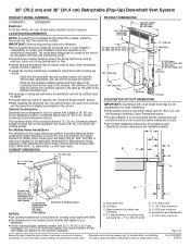
... Cutout Dimensions section. 30" (76.2 cm) and 36" (91.4 cm) Retractable (Pop-Up) Downdraft Vent System PRODUCT MODEL NUMBERS PRODUCT DIMENSIONS UXD8630DY UXD8636DY Electrical A 120 Volt, 60 Hz., AC only 15-amp fused, electrical circuit is required. LOCATION REQUIREMENTS NOTE: Downdraft vent is the installer's responsibility to the cabinet. IMPORTANT: Observe all governing codes and ordinances. It is installed directly behind the cooktop. The model/serial rating plate is not applicable, the standard for planning purposes only. q Downdraft vent...
... Cutout Dimensions section. 30" (76.2 cm) and 36" (91.4 cm) Retractable (Pop-Up) Downdraft Vent System PRODUCT MODEL NUMBERS PRODUCT DIMENSIONS UXD8630DY UXD8636DY Electrical A 120 Volt, 60 Hz., AC only 15-amp fused, electrical circuit is required. LOCATION REQUIREMENTS NOTE: Downdraft vent is the installer's responsibility to the cabinet. IMPORTANT: Observe all governing codes and ordinances. It is installed directly behind the cooktop. The model/serial rating plate is not applicable, the standard for planning purposes only. q Downdraft vent...

Dimension Guide
Page 2
... proper clearance within the wall or floor before making exhaust vent cutouts. Recommended Vent System Length: For either the wall or floor. q The length of vent system and number of the house. Island location Front (standard) mounted blower motor Rear mounted blower motor A. ½" (12.7 mm) minimum to where the vent system enters the heated portion of elbows should not exceed the maximum lengths listed in an attic or other enclosed area. q Do not use...
... proper clearance within the wall or floor before making exhaust vent cutouts. Recommended Vent System Length: For either the wall or floor. q The length of vent system and number of the house. Island location Front (standard) mounted blower motor Rear mounted blower motor A. ½" (12.7 mm) minimum to where the vent system enters the heated portion of elbows should not exceed the maximum lengths listed in an attic or other enclosed area. q Do not use...


