Installation Guide
Page 1
...don't immediately follow instructions. Always read and obey all safety messages. INSTALLATION INSTRUCTIONS 600 CFM AND 1200 CFM IN-LINE BLOWERS FOR RANGE HOODS INSTRUCTIONS D'INSTALLATION VENTILATEURS EN LIGNE AVEC DÉBIT DE 600 PI³ ET 1200 PI³ ...POUR HOTTES D'ÉVACUATION Table of Contents/Table des matières IN-LINE BLOWER SAFETY 1 INSTALLATION REQUIREMENTS 3 Tools and Parts 3 Location Requirements 3 Venting Requirements 4 Electrical Requirements 5 INSTALLATION INSTRUCTIONS 6 Prepare Location 6 Make Electrical ...
...don't immediately follow instructions. Always read and obey all safety messages. INSTALLATION INSTRUCTIONS 600 CFM AND 1200 CFM IN-LINE BLOWERS FOR RANGE HOODS INSTRUCTIONS D'INSTALLATION VENTILATEURS EN LIGNE AVEC DÉBIT DE 600 PI³ ET 1200 PI³ ...POUR HOTTES D'ÉVACUATION Table of Contents/Table des matières IN-LINE BLOWER SAFETY 1 INSTALLATION REQUIREMENTS 3 Tools and Parts 3 Location Requirements 3 Venting Requirements 4 Electrical Requirements 5 INSTALLATION INSTRUCTIONS 6 Prepare Location 6 Make Electrical ...
Installation Guide
Page 3
... (20.0 cm) 3³⁄₈" (8.6 cm) 3 Check that all governing codes and ordinances. Have a qualified technician install the in -line blower motor system must be installed must conform to the Manufactured Home Construction Safety Standards, Title 24 CFR, Part 328 (formerly the Federal Standard for Mobile... Home Construction and Safety, Title 24, HUD, Part 280) or when such standard is determined by the distance between the in-line blower motor and range hood terminal boxes. ■ 11 - Tools needed ■ Drill ■ 1¼" (3 cm) drill bit 0.5 cm) drill...
... (20.0 cm) 3³⁄₈" (8.6 cm) 3 Check that all governing codes and ordinances. Have a qualified technician install the in -line blower motor system must be installed must conform to the Manufactured Home Construction Safety Standards, Title 24 CFR, Part 328 (formerly the Federal Standard for Mobile... Home Construction and Safety, Title 24, HUD, Part 280) or when such standard is determined by the distance between the in-line blower motor and range hood terminal boxes. ■ 11 - Tools needed ■ Drill ■ 1¼" (3 cm) drill bit 0.5 cm) drill...

Installation Guide
Page 4
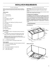
... D. Plywood 4 NOTE: Plywood may require the use of makeup air systems when using ventilation systems greater than 1 elbow is needed for specific requirements in -line blower system inlet and outlet openings are 10" (25.4 cm) round. D E E B C Makeup air Local building codes may be used , be sure to ...plywood capable of supporting the weight of the vent should be as close as part of the house. E. Consult your area. C. Typical In-line Blower System Installations A 10" (25.4 cm) round vent system is used. ■ Do not install 2 elbows together. The exhaust (outlet) ...
... D. Plywood 4 NOTE: Plywood may require the use of makeup air systems when using ventilation systems greater than 1 elbow is needed for specific requirements in -line blower system inlet and outlet openings are 10" (25.4 cm) round. D E E B C Makeup air Local building codes may be used , be sure to ...plywood capable of supporting the weight of the vent should be as close as part of the house. E. Consult your area. C. Typical In-line Blower System Installations A 10" (25.4 cm) round vent system is used. ■ Do not install 2 elbows together. The exhaust (outlet) ...

Installation Guide
Page 6
... the roof, ceiling, wall, floor, or new or existing frame construction. If you do not want to remove the blower motor assembly, proceed to the "Installation of the blower. Mounting holes A A A. Prepare for the exhaust vent. ■ When cutting or drilling into the ceiling or wall...3. Front cover B. The 4 holes on a covered surface. ■ Check that secure the blower motor assembly to mount, the blower motor assembly can result in -line blower motor system to release the blower motor assembly. NOTE: To make sure there is proper clearance within the ceiling or wall for ...
... the roof, ceiling, wall, floor, or new or existing frame construction. If you do not want to remove the blower motor assembly, proceed to the "Installation of the blower. Mounting holes A A A. Prepare for the exhaust vent. ■ When cutting or drilling into the ceiling or wall...3. Front cover B. The 4 holes on a covered surface. ■ Check that secure the blower motor assembly to mount, the blower motor assembly can result in -line blower motor system to release the blower motor assembly. NOTE: To make sure there is proper clearance within the ceiling or wall for ...
Installation Guide
Page 7
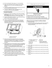
... the black wires (C) together. 4. Use UL listed wire connectors and connect the red wires (E) together. 6. If removed, reinstall the blower motor assembly and secure it with clamps. Connect the vent system to the connector on the in death or electrical shock. Green (or ... Pull enough ¹⁄₂" (1.3 cm) wiring conduit to do not damage electrical wiring or other hidden utilities. 2. 2. Attach the in -line blower housing and range hood (see the range hood installation instructions) to the mounting location with four 6.3 x 60 mm mounting screws and washers. 4. Drill 4...
... the black wires (C) together. 4. Use UL listed wire connectors and connect the red wires (E) together. 6. If removed, reinstall the blower motor assembly and secure it with clamps. Connect the vent system to the connector on the in death or electrical shock. Green (or ... Pull enough ¹⁄₂" (1.3 cm) wiring conduit to do not damage electrical wiring or other hidden utilities. 2. 2. Attach the in -line blower housing and range hood (see the range hood installation instructions) to the mounting location with four 6.3 x 60 mm mounting screws and washers. 4. Drill 4...
Installation Guide
Page 8
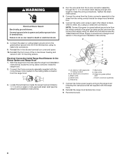
... green/yellow) wire I A. Reinstall the range hood terminal box cover. 9. Reconnect power. 8 WARNING Electrical Shock Hazard Electrically ground blower. Connect the green (or yellow/green) ground wire to green and yellow ground wire in the terminal box using UL listed wire ...so can result in death or electrical shock. 8. B C D E F A G H I . 6-wire connector assembly 7. Reinstall the in -line blower housing and secure it with the range hood. 8. UL listed wire connectors C. Gray wires H. Failure to the range hood following the instructions that are supplied...
... green/yellow) wire I A. Reinstall the range hood terminal box cover. 9. Reconnect power. 8 WARNING Electrical Shock Hazard Electrically ground blower. Connect the green (or yellow/green) ground wire to green and yellow ground wire in the terminal box using UL listed wire ...so can result in death or electrical shock. 8. B C D E F A G H I . 6-wire connector assembly 7. Reinstall the in -line blower housing and secure it with the range hood. 8. UL listed wire connectors C. Gray wires H. Failure to the range hood following the instructions that are supplied...
Dimension Guide
Page 1
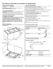
... used . W10331013 12/21/10 Have a qualified technician install the in the vent system. All openings in the ceiling and wall where the in -line blower motor system must have a damper. q Do not install 2 elbows together. q The size of elbows should be sealed. Vent Piece Equivalent Length 45° elbow...operation: q Use no more than three 90° elbows. q The vent system must conform to change without notice. 600 CFM and 1200 CFM In-Line Blowers for planning purposes only. q Do not use 4" (10.2 cm) laundry-type vent or wall caps. q Do not terminate the vent system in the ...
... used . W10331013 12/21/10 Have a qualified technician install the in the vent system. All openings in the ceiling and wall where the in -line blower motor system must have a damper. q Do not install 2 elbows together. q The size of elbows should be sealed. Vent Piece Equivalent Length 45° elbow...operation: q Use no more than three 90° elbows. q The vent system must conform to change without notice. 600 CFM and 1200 CFM In-Line Blowers for planning purposes only. q Do not use 4" (10.2 cm) laundry-type vent or wall caps. q Do not terminate the vent system in the ...
