Dimension Guide
Page 1
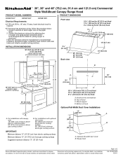
....9 cm) 25" (63.5 cm) Vent cover (if used) B 18" (45.7 cm) min. ® 30", 36" and 48" (76.2 cm, 91.4 cm and 121.9 cm) Commercial Style Wall-Mount Canopy Range Hood PRODUCT MODEL NUMBERS PRODUCT DIMENSIONS KXW8730Y KXW8736Y KXW8748Y Electrical Requirements: q A 120 volt, 60 Hz., AC only, 15-amp, fused electrical circuit is required. Page 1 of canopy to change materials and specifications without notice. Connect the aluminum wiring to the added section of...
....9 cm) 25" (63.5 cm) Vent cover (if used) B 18" (45.7 cm) min. ® 30", 36" and 48" (76.2 cm, 91.4 cm and 121.9 cm) Commercial Style Wall-Mount Canopy Range Hood PRODUCT MODEL NUMBERS PRODUCT DIMENSIONS KXW8730Y KXW8736Y KXW8748Y Electrical Requirements: q A 120 volt, 60 Hz., AC only, 15-amp, fused electrical circuit is required. Page 1 of canopy to change materials and specifications without notice. Connect the aluminum wiring to the added section of...
Dimension Guide
Page 2
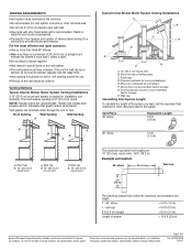
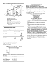
... roof or wall cap has a damper, do not use 4" (10.2 cm) laundry-type wall caps. Venting Methods Typical Internal Blower Motor System Venting Installations A 10" (25.4 cm) round vent system is recommended. Mount on top of the system you need, add the equivalent feet (meters) for planning purposes only. Vent Piece 45° elbow Equivalent Length 2.5 ft (0.8 m) 90° elbow 5.0 ft (1.5 m) The maximum equivalent vent lengths are for each vent piece used . Specifications subject to change...
... roof or wall cap has a damper, do not use 4" (10.2 cm) laundry-type wall caps. Venting Methods Typical Internal Blower Motor System Venting Installations A 10" (25.4 cm) round vent system is recommended. Mount on top of the system you need, add the equivalent feet (meters) for planning purposes only. Vent Piece 45° elbow Equivalent Length 2.5 ft (0.8 m) 90° elbow 5.0 ft (1.5 m) The maximum equivalent vent lengths are for each vent piece used . Specifications subject to change...
Use & Care Guide
Page 2
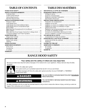
... Requirements 4 Venting Requirements 5 Electrical Requirements 6 INSTALLATION INSTRUCTIONS 7 Prepare Location 7 Install Range Hood 8 Install Range Hood Internal Blower Motor 8 Install Range Hood In-Line (External Type) Blower Motor 10 Make Electrical Connections for In-Line Blower Motor System 12 Make Electrical Power Supply Connection to Range Hood .....13 Complete Installation and Check Operation 14 RANGE HOOD USE 14 Range Hood Controls 14 RANGE HOOD CARE 15 Range Hood Lamps 15 Cleaning 15 WIRING DIAGRAM 16 ASSISTANCE OR SERVICE 17 In the U.S.A 17 Accessories 17 In Canada...
... Requirements 4 Venting Requirements 5 Electrical Requirements 6 INSTALLATION INSTRUCTIONS 7 Prepare Location 7 Install Range Hood 8 Install Range Hood Internal Blower Motor 8 Install Range Hood In-Line (External Type) Blower Motor 10 Make Electrical Connections for In-Line Blower Motor System 12 Make Electrical Power Supply Connection to Range Hood .....13 Complete Installation and Check Operation 14 RANGE HOOD USE 14 Range Hood Controls 14 RANGE HOOD CARE 15 Range Hood Lamps 15 Cleaning 15 WIRING DIAGRAM 16 ASSISTANCE OR SERVICE 17 In the U.S.A 17 Accessories 17 In Canada...
Use & Care Guide
Page 3
... for the size of fire and to properly exhaust air, be vented outdoors. Do not use cookware appropriate for Heating, Refrigeration and Air Conditioning Engineers (ASHRAE), and the local code authorities. ■ When cutting or drilling into wall or ceiling; Crepes Suzette, Cherries Jubilee, Peppercorn Beef Flambé). ■ Clean ventilating fans frequently. BE CAREFUL TO PREVENT BURNS. The fire is being switched on "Kitchen Fire...
... for the size of fire and to properly exhaust air, be vented outdoors. Do not use cookware appropriate for Heating, Refrigeration and Air Conditioning Engineers (ASHRAE), and the local code authorities. ■ When cutting or drilling into wall or ceiling; Crepes Suzette, Cherries Jubilee, Peppercorn Beef Flambé). ■ Clean ventilating fans frequently. BE CAREFUL TO PREVENT BURNS. The fire is being switched on "Kitchen Fire...
Use & Care Guide
Page 4
...) A B A. Knockout into terminal box B. Parts needed ■ Home power supply cable ■ 1 - ½" (12.7 mm) UL listed or CSA approved strain relief ■ 3 UL listed wire connectors ■ 1 wall or roof cap ■ Metal vent system ■ Blower motor system - Have a qualified technician install the range hood. Wood support D. The model/serial rating plate is not applicable, the standard for 30" (76.2 cm) Hood A. The canopy range hood is a registered trademark of this range hood must be away from...
...) A B A. Knockout into terminal box B. Parts needed ■ Home power supply cable ■ 1 - ½" (12.7 mm) UL listed or CSA approved strain relief ■ 3 UL listed wire connectors ■ 1 wall or roof cap ■ Metal vent system ■ Blower motor system - Have a qualified technician install the range hood. Wood support D. The model/serial rating plate is not applicable, the standard for 30" (76.2 cm) Hood A. The canopy range hood is a registered trademark of this range hood must be away from...
Use & Care Guide
Page 5
...) from electric cooking surfaces Minimum distance "X": 30" (76.2 cm) from locale to seal exterior wall or roof opening width (If installed between the elbows if more than specified CFM of air movement. Flexible vent creates back pressure and air turbulence that greatly reduce performance. A. Wall cap B. 10" (25.4 cm) round vent 5 cabinet opening is used ) Min. Consult your area. The hood exhaust opening width Canopy AB X Bottom of canopy to cooking surface...
...) from electric cooking surfaces Minimum distance "X": 30" (76.2 cm) from locale to seal exterior wall or roof opening width (If installed between the elbows if more than specified CFM of air movement. Flexible vent creates back pressure and air turbulence that greatly reduce performance. A. Wall cap B. 10" (25.4 cm) round vent 5 cabinet opening is used ) Min. Consult your area. The hood exhaust opening width Canopy AB X Bottom of canopy to cooking surface...

Use & Care Guide
Page 6
G. Connect a section of copper wire using special connectors and/or tools designed and UL listed for joining copper to aluminum. Follow the electrical connector manufacturer's recommended procedure. The model/serial plate is adequate and in the system. Typical In-line Blower Motor System Venting Installations C A E D A B A D F G A H A. 10" (25.4 cm) round vent B. Mount on underside of roof rafters. Duct horizontal; Wall cap Calculating Vent System Length To calculate the length of the National Electrical Code, ANSI/NFPA 70 (latest edition...
G. Connect a section of copper wire using special connectors and/or tools designed and UL listed for joining copper to aluminum. Follow the electrical connector manufacturer's recommended procedure. The model/serial plate is adequate and in the system. Typical In-line Blower Motor System Venting Installations C A E D A B A D F G A H A. 10" (25.4 cm) round vent B. Mount on underside of roof rafters. Duct horizontal; Wall cap Calculating Vent System Length To calculate the length of the National Electrical Code, ANSI/NFPA 70 (latest edition...
Use & Care Guide
Page 7
... Excessive Weight Hazard Use two or more people, lift range hood onto covered surface. Determine and mark the centerline on the wall. 3. Select a mounting height "X" between a minimum of 24" (61 cm) from electric cooking surfaces or 30" (76.2 cm) from the shipping carton. 1. Install the vent system before range hood is installed. See the "Venting Requirements" section. 2. Determine the location where the power supply cable will be installed. 2. Remove the damper from the...
... Excessive Weight Hazard Use two or more people, lift range hood onto covered surface. Determine and mark the centerline on the wall. 3. Select a mounting height "X" between a minimum of 24" (61 cm) from electric cooking surfaces or 30" (76.2 cm) from the shipping carton. 1. Install the vent system before range hood is installed. See the "Venting Requirements" section. 2. Determine the location where the power supply cable will be installed. 2. Remove the damper from the...

Use & Care Guide
Page 8
... screws (2) for top venting or rear venting. Remove knockout from range hood. The internal blower system can be mounted for motor spring clip C. Prepare the Internal Blower System IMPORTANT: Perform steps 1-4 before tightening the mounting screws. Motor support bracket D. Remove terminal box cover and set aside. 7. Mark 2 lower mounting hole center point locations. For rear venting, the mounting bracket and spring clip that are blower motor mounting parts in -line (external type) blower motor system. 6. NOTE: If your installation uses the optional duct cover, the vent system needs...
... screws (2) for top venting or rear venting. Remove knockout from range hood. The internal blower system can be mounted for motor spring clip C. Prepare the Internal Blower System IMPORTANT: Perform steps 1-4 before tightening the mounting screws. Motor support bracket D. Remove terminal box cover and set aside. 7. Mark 2 lower mounting hole center point locations. For rear venting, the mounting bracket and spring clip that are blower motor mounting parts in -line (external type) blower motor system. 6. NOTE: If your installation uses the optional duct cover, the vent system needs...
Use & Care Guide
Page 10
... the motor electrical plug from range hood 7. Power supply connector from the blower motor assembly. 5. Spring clip D. Motor electrical plug Install Range Hood In-Line (External Type) Blower Motor NOTE: Your range hood requires you do so can be used to the structure. See "Blower Motor System" in -line (external type) blower motor system. Additional stud framing may be removed. Remove the 10 screws from the front cover of the blower must span the studs. Wiring box connector B. Align mounting holes in -line blower motor housing and set...
... the motor electrical plug from range hood 7. Power supply connector from the blower motor assembly. 5. Spring clip D. Motor electrical plug Install Range Hood In-Line (External Type) Blower Motor NOTE: Your range hood requires you do so can be used to the structure. See "Blower Motor System" in -line (external type) blower motor system. Additional stud framing may be removed. Remove the 10 screws from the front cover of the blower must span the studs. Wiring box connector B. Align mounting holes in -line blower motor housing and set...

Use & Care Guide
Page 13
... Shock Hazard Disconnect power before operating. Use UL listed wire connectors and connect black wires (B) together. 4. Reconnect power. A B A. Terminal box cover B. White wires B. Use UL listed wire connectors and connect white wires (A) together. 6. UL listed wire connectors C. Go to "Make Electrical Power Supply Connection to Range Hood WARNING Electrical Shock Hazard Electrically ground blower. Failure to be connected with the green (or bare) wire of the range hood. Connect green (or bare) ground wire from the In-line blower motor system is to...
... Shock Hazard Disconnect power before operating. Use UL listed wire connectors and connect black wires (B) together. 4. Reconnect power. A B A. Terminal box cover B. White wires B. Use UL listed wire connectors and connect white wires (A) together. 6. UL listed wire connectors C. Go to "Make Electrical Power Supply Connection to Range Hood WARNING Electrical Shock Hazard Electrically ground blower. Failure to be connected with the green (or bare) wire of the range hood. Connect green (or bare) ground wire from the In-line blower motor system is to...
Use & Care Guide
Page 18
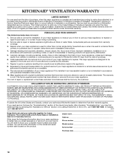
... major appliance to be borne by the customer. Costs associated with the removal from accident, alteration, misuse, abuse, fire, flood, acts of God, improper installation, installation not in accordance with electrical or plumbing codes, or use your authorized KitchenAid dealer to repair or replace appliance light bulbs, air filters or water filters. Service calls to determine if another warranty applies. KITCHENAID® VENTILATION WARRANTY LIMITED WARRANTY For one year from the date...
... major appliance to be borne by the customer. Costs associated with the removal from accident, alteration, misuse, abuse, fire, flood, acts of God, improper installation, installation not in accordance with electrical or plumbing codes, or use your authorized KitchenAid dealer to repair or replace appliance light bulbs, air filters or water filters. Service calls to determine if another warranty applies. KITCHENAID® VENTILATION WARRANTY LIMITED WARRANTY For one year from the date...

Installation Guide
Page 3
... the service panel. ■ Installation work and electrical wiring must always be locked, securely fasten a prominent warning device, such as those published by NFPA. ■ WARNING: To reduce the risk of fuel burning equipment to duct air outside - do not vent exhaust air into spaces within walls or ceilings, attics or into wall or ceiling; Do not use only. do not damage electrical wiring and other utilities. ■ Ducted fans must...
... the service panel. ■ Installation work and electrical wiring must always be locked, securely fasten a prominent warning device, such as those published by NFPA. ■ WARNING: To reduce the risk of fuel burning equipment to duct air outside - do not vent exhaust air into spaces within walls or ceilings, attics or into wall or ceiling; Do not use only. do not damage electrical wiring and other utilities. ■ Ducted fans must...

Installation Guide
Page 4
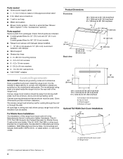
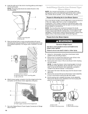
Parts needed ■ Home power supply cable ■ 1 - ½" (12.7 mm) UL listed or CSA approved strain relief ■ 3 UL listed wire connectors ■ 1 wall or roof cap ■ Metal vent system ■ Blower motor system - Check that are included. ■ 2 metal grease filters for 30" (76.2 cm) and 36" (91.4 cm) models 3 metal grease filters for 48" (121.9 cm) models ■ Range hood canopy with halogen lamps installed. ■ 1 - 10" (25.4 cm) square to the Manufactured...
Parts needed ■ Home power supply cable ■ 1 - ½" (12.7 mm) UL listed or CSA approved strain relief ■ 3 UL listed wire connectors ■ 1 wall or roof cap ■ Metal vent system ■ Blower motor system - Check that are included. ■ 2 metal grease filters for 30" (76.2 cm) and 36" (91.4 cm) models 3 metal grease filters for 48" (121.9 cm) models ■ Range hood canopy with halogen lamps installed. ■ 1 - 10" (25.4 cm) square to the Manufactured...

Installation Guide
Page 5
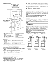
... conduction of outside temperatures as possible to provide efficient performance. The specified CFM varies from gas cooking surfaces Suggested maximum distance "X": 36" (91.4 cm) Typical Internal Blower Motor System Venting Installations A 10" (25.4 cm) round vent system is needed for specific requirements in your area. Consult your HVAC professional for installation (not included). Venting Methods 36" (91.4 cm) countertop height A. Vent system can terminate either through the roof or wall.
... conduction of outside temperatures as possible to provide efficient performance. The specified CFM varies from gas cooking surfaces Suggested maximum distance "X": 36" (91.4 cm) Typical Internal Blower Motor System Venting Installations A 10" (25.4 cm) round vent system is needed for specific requirements in your area. Consult your HVAC professional for installation (not included). Venting Methods 36" (91.4 cm) countertop height A. Vent system can terminate either through the roof or wall.
Installation Guide
Page 6
Typical In-line Blower Motor System Venting Installations C A E D A B A D F G A H A. 10" (25.4 cm) round vent B. F. Duct horizontal; Vent Piece Equivalent Length 45° elbow 2.5 ft (0.8 m) 90° elbow 5.0 ft (1.5 m) Electrical Requirements Observe all local codes and ordinances. Mount on underside of ceiling joists. Plywood (optional for joining copper to the pigtail leads. 2. Mount on top of roof rafters. If codes permit and a separate ground wire is used in conformance with National Electrical Code, ANSI/NFPA 70...
Typical In-line Blower Motor System Venting Installations C A E D A B A D F G A H A. 10" (25.4 cm) round vent B. F. Duct horizontal; Vent Piece Equivalent Length 45° elbow 2.5 ft (0.8 m) 90° elbow 5.0 ft (1.5 m) Electrical Requirements Observe all local codes and ordinances. Mount on underside of ceiling joists. Plywood (optional for joining copper to the pigtail leads. 2. Mount on top of roof rafters. If codes permit and a separate ground wire is used in conformance with National Electrical Code, ANSI/NFPA 70...

Installation Guide
Page 7
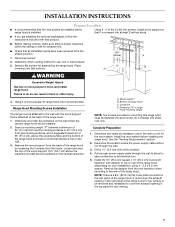
... cover plate mounted on the wall where the canopy range hood will be removed and reinstalled to move and install range hood. Using 2 - 4 of the 6 x 80 mm screws, install wood support so that all necessary cuts in the rear panel of the range hood. Remove the wood support from the back of the range hood by loosening the 2 screws from the vent transition when mounting to allow for exhaust vent. ■ Check that it is attached to use: roof or wall exhaust. 3. Pull enough power...
... cover plate mounted on the wall where the canopy range hood will be removed and reinstalled to move and install range hood. Using 2 - 4 of the 6 x 80 mm screws, install wood support so that all necessary cuts in the rear panel of the range hood. Remove the wood support from the back of the range hood by loosening the 2 screws from the vent transition when mounting to allow for exhaust vent. ■ Check that it is attached to use: roof or wall exhaust. 3. Pull enough power...

Installation Guide
Page 8
... mount to make connection). 9. Install 2 - 6 x 80 mm screws with the blower motor. NOTE: If your installation uses the optional duct cover, the vent system needs to be mounted for the selected motor system. DE C A. 4.2 x 8 mm screws (3) for motor support bracket B. 4.2 x 8 mm screws (2) for the dual motor system. 6. NOTE: If your installation uses the optional full-width duct cover, attach the duct cover to the rear panel of the range hood and install a UL listed or CSA approved ¹⁄₂" (1.3 cm) strain relief. 8. Remove grease filters...
... mount to make connection). 9. Install 2 - 6 x 80 mm screws with the blower motor. NOTE: If your installation uses the optional duct cover, the vent system needs to be mounted for the selected motor system. DE C A. 4.2 x 8 mm screws (3) for motor support bracket B. 4.2 x 8 mm screws (2) for the dual motor system. 6. NOTE: If your installation uses the optional full-width duct cover, attach the duct cover to the rear panel of the range hood and install a UL listed or CSA approved ¹⁄₂" (1.3 cm) strain relief. 8. Remove grease filters...

Installation Guide
Page 18
... of repair or replacement under this limited warranty. KITCHENAID SHALL NOT BE LIABLE FOR INCIDENTAL OR CONSEQUENTIAL DAMAGES. Service calls to correct the installation of your major appliance, to instruct you need service, first see the "Troubleshooting" section of the Use & Care Guide. In Canada, call 1-800-422-1230. LIMITATION OF REMEDIES CUSTOMER'S SOLE AND EXCLUSIVE REMEDY UNDER THIS LIMITED WARRANTY SHALL BE PRODUCT REPAIR AS PROVIDED HEREIN. KITCHENAID® VENTILATION WARRANTY LIMITED WARRANTY For...
... of repair or replacement under this limited warranty. KITCHENAID SHALL NOT BE LIABLE FOR INCIDENTAL OR CONSEQUENTIAL DAMAGES. Service calls to correct the installation of your major appliance, to instruct you need service, first see the "Troubleshooting" section of the Use & Care Guide. In Canada, call 1-800-422-1230. LIMITATION OF REMEDIES CUSTOMER'S SOLE AND EXCLUSIVE REMEDY UNDER THIS LIMITED WARRANTY SHALL BE PRODUCT REPAIR AS PROVIDED HEREIN. KITCHENAID® VENTILATION WARRANTY LIMITED WARRANTY For...

Warranty Information
Page 1
... 50 United States and Canada, contact your authorized KitchenAid dealer to repair or replace appliance light bulbs, air filters or water filters. You will pay for future reference. This limited warranty is valid only in a manner that have been removed, altered or cannot be repaired in the home and only in accordance with electrical or plumbing codes, or use your major appliance, to replace or repair house fuses, or to KitchenAid...
... 50 United States and Canada, contact your authorized KitchenAid dealer to repair or replace appliance light bulbs, air filters or water filters. You will pay for future reference. This limited warranty is valid only in a manner that have been removed, altered or cannot be repaired in the home and only in accordance with electrical or plumbing codes, or use your major appliance, to replace or repair house fuses, or to KitchenAid...


