Dimension Guide
Page 1
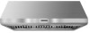
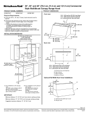
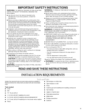
... wire to change without notice. clearance upper cabinet to improve Dimensions are for joining copper to aluminum. Knockout into terminal box B. Range hood 18" (45.7 cm) A B Because Whirlpool Corporation policy includes a continuous commitment to countertop Min. Aluminum/copper connection must conform with...notice. ® 30", 36" and 48" (76.2 cm, 91.4 cm and 121.9 cm) Commercial Style Wall-Mount Canopy Range Hood PRODUCT MODEL NUMBERS PRODUCT DIMENSIONS KXW8730Y KXW8736Y KXW8748Y Electrical Requirements: q A 120 volt, 60 Hz., AC only, 15-amp, fused electrical circuit...
... wire to change without notice. clearance upper cabinet to improve Dimensions are for joining copper to aluminum. Knockout into terminal box B. Range hood 18" (45.7 cm) A B Because Whirlpool Corporation policy includes a continuous commitment to countertop Min. Aluminum/copper connection must conform with...notice. ® 30", 36" and 48" (76.2 cm, 91.4 cm and 121.9 cm) Commercial Style Wall-Mount Canopy Range Hood PRODUCT MODEL NUMBERS PRODUCT DIMENSIONS KXW8730Y KXW8736Y KXW8748Y Electrical Requirements: q A 120 volt, 60 Hz., AC only, 15-amp, fused electrical circuit...
Dimension Guide
Page 2
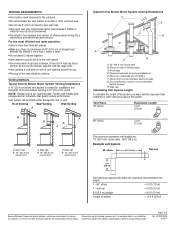
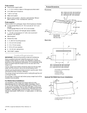
.... q Do not install 2 elbows together. q The size of elbows should be kept to a minimum to provide efficient performance. Roof caps D. G. Instructions packed with the range hood. q Make sure there is a minimum of 24" (61.0 cm) of ceiling joists. If the roof or wall cap has a damper, do not use 4" (10.2 ...18.3 m) Example vent system 90 elbow 6 ft (1.8 m) Wall cap 2 ft (0.6 m) The following example falls within the maximum recommended vent length. 1 - 90° elbow = 5.0 ft (1.5 m) 1 - The hood exhaust opening around the cap. Duct horizontal; W10331007B 3/30/11
.... q Do not install 2 elbows together. q The size of elbows should be kept to a minimum to provide efficient performance. Roof caps D. G. Instructions packed with the range hood. q Make sure there is a minimum of 24" (61.0 cm) of ceiling joists. If the roof or wall cap has a damper, do not use 4" (10.2 ...18.3 m) Example vent system 90 elbow 6 ft (1.8 m) Wall cap 2 ft (0.6 m) The following example falls within the maximum recommended vent length. 1 - 90° elbow = 5.0 ft (1.5 m) 1 - The hood exhaust opening around the cap. Duct horizontal; W10331007B 3/30/11
Use & Care Guide
Page 1
...AND 121.9 CM) COMMERCIAL STYLE WALL-MOUNT CANOPY RANGE HOOD Installation Instructions and Use & Care Guide For questions about features, operation/performance, parts, accessories or service, call: 1-800-422-1230 or visit our website at www.kitchenaid.com In Canada, for assistance, installation and service, call... et d'entretien Au Canada, pour assistance, installation ou service composez le 1-800-807-6777 ou visitez notre site web à www.kitchenaid.ca Table of Contents/Table des matières 2 IMPORTANT: READ AND SAVE THESE INSTRUCTIONS. LI3ZAB/W10331007B IMPORTANT : LIRE ET CONSERVER ...
...AND 121.9 CM) COMMERCIAL STYLE WALL-MOUNT CANOPY RANGE HOOD Installation Instructions and Use & Care Guide For questions about features, operation/performance, parts, accessories or service, call: 1-800-422-1230 or visit our website at www.kitchenaid.com In Canada, for assistance, installation and service, call... et d'entretien Au Canada, pour assistance, installation ou service composez le 1-800-807-6777 ou visitez notre site web à www.kitchenaid.ca Table of Contents/Table des matières 2 IMPORTANT: READ AND SAVE THESE INSTRUCTIONS. LI3ZAB/W10331007B IMPORTANT : LIRE ET CONSERVER ...

Use & Care Guide
Page 2
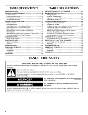
... Connections for In-Line Blower Motor System 12 Make Electrical Power Supply Connection to Range Hood .....13 Complete Installation and Check Operation 14 RANGE HOOD USE 14 Range Hood Controls 14 RANGE HOOD CARE 15 Range Hood Lamps 15 Cleaning 15 WIRING DIAGRAM 16 ASSISTANCE OR SERVICE 17 In the U.S.A 17 ...ère 33 Nettoyage 33 SCHÉMA DE CÂBLAGE 34 ASSISTANCE OU SERVICE 35 Au Canada 35 Accessoires 35 GARANTIE 36 RANGE HOOD SAFETY Your safety and the safety of injury, and tell you don't follow instructions. We have provided many important safety messages in this...
... Connections for In-Line Blower Motor System 12 Make Electrical Power Supply Connection to Range Hood .....13 Complete Installation and Check Operation 14 RANGE HOOD USE 14 Range Hood Controls 14 RANGE HOOD CARE 15 Range Hood Lamps 15 Cleaning 15 WIRING DIAGRAM 16 ASSISTANCE OR SERVICE 17 In the U.S.A 17 ...ère 33 Nettoyage 33 SCHÉMA DE CÂBLAGE 34 ASSISTANCE OU SERVICE 35 Au Canada 35 Accessoires 35 GARANTIE 36 RANGE HOOD SAFETY Your safety and the safety of injury, and tell you don't follow instructions. We have provided many important safety messages in this...
Use & Care Guide
Page 3
... bit if installing optional backsplash kit 5 mm) drill bit if installing an in accordance with a close fitting lid, cookie sheet, or metal tray, then turn hood ON when cooking at high settings. WARNING: TO REDUCE THE RISK OF INJURY TO PERSONS IN THE EVENT OF A RANGE TOP GREASE FIRE, OBSERVE THE...
... bit if installing optional backsplash kit 5 mm) drill bit if installing an in accordance with a close fitting lid, cookie sheet, or metal tray, then turn hood ON when cooking at high settings. WARNING: TO REDUCE THE RISK OF INJURY TO PERSONS IN THE EVENT OF A RANGE TOP GREASE FIRE, OBSERVE THE...
Use & Care Guide
Page 4
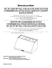
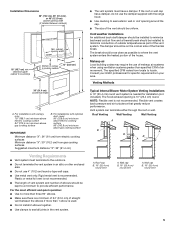
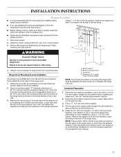
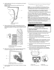
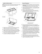
... the Federal Standard for Mobile Home Construction and Safety, Title 24, HUD, Part 280) or when such standard is located inside the range hood on the model/serial rating plate. The model/serial rating plate is not applicable, the standard for 48" (121.9 cm) models ■ Range...such as windows, doors and strong heating vents. Wood support D. internal or external (See "Blower Motor System" in ceiling and wall where canopy range hood will be sealed. Cabinet opening dimensions that all governing codes and ordinances. Product Dimensions Front view 18 45.9 cm) for 48" (121.9 cm...
... the Federal Standard for Mobile Home Construction and Safety, Title 24, HUD, Part 280) or when such standard is located inside the range hood on the model/serial rating plate. The model/serial rating plate is not applicable, the standard for 48" (121.9 cm) models ■ Range...such as windows, doors and strong heating vents. Wood support D. internal or external (See "Blower Motor System" in ceiling and wall where canopy range hood will be sealed. Cabinet opening dimensions that all governing codes and ordinances. Product Dimensions Front view 18 45.9 cm) for 48" (121.9 cm...
Use & Care Guide
Page 5
.... ■ Make sure there is a minimum of 24" (61.0 cm) of straight vent between cabinets) 18" (45.7 cm) min. A. For installations with the range hood. ■ Use caulking to seal exterior wall or roof opening width Canopy AB X Bottom of canopy to cooking surface 13" (33.0 cm) ■ The vent... and air turbulence that greatly reduce performance. Consult your area. The damper should be uniform. Venting Methods 36" (91.4 cm) countertop height A. The hood exhaust opening width (If installed between the elbows if more than specified CFM of the vent system.
.... ■ Make sure there is a minimum of 24" (61.0 cm) of straight vent between cabinets) 18" (45.7 cm) min. A. For installations with the range hood. ■ Use caulking to seal exterior wall or roof opening width Canopy AB X Bottom of canopy to cooking surface 13" (33.0 cm) ■ The vent... and air turbulence that greatly reduce performance. Consult your area. The damper should be uniform. Venting Methods 36" (91.4 cm) countertop height A. The hood exhaust opening width (If installed between the elbows if more than specified CFM of the vent system.
Use & Care Guide
Page 6
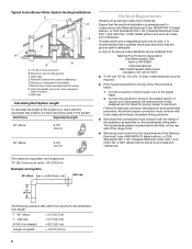
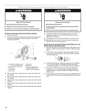
... 2.5 ft (0.8 m) 90° elbow 5.0 ft (1.5 m) Electrical Requirements Observe all local codes and ordinances. Connect a section of solid copper wire to the requirements of the range hood. ■ Wire sizes must conform with the rating of ceiling joists. Follow the electrical connector manufacturer's recommended procedure. The model/serial plate is adequate and...
... 2.5 ft (0.8 m) 90° elbow 5.0 ft (1.5 m) Electrical Requirements Observe all local codes and ordinances. Connect a section of solid copper wire to the requirements of the range hood. ■ Wire sizes must conform with the rating of ceiling joists. Follow the electrical connector manufacturer's recommended procedure. The model/serial plate is adequate and...
Use & Care Guide
Page 7
...on your installation), using 4 - 3.5 x 9.5 mm screws. Centerline D. Remove the damper from gas cooking surfaces, and a suggested maximum of the range hood. Place "X" B covering over that is attached to the wall with that product. ■ Before making cutouts, make all installation parts have been removed from... included with the wood support that surface. Determine the location where the power supply cable will be removed and reinstalled to move and install range hood. Using 2 - 4 of the 6 x 80 mm screws, install wood support so that it is a 8¾" (22.2 cm) flat cover ...
...on your installation), using 4 - 3.5 x 9.5 mm screws. Centerline D. Remove the damper from gas cooking surfaces, and a suggested maximum of the range hood. Place "X" B covering over that is attached to the wall with that product. ■ Before making cutouts, make all installation parts have been removed from... included with the wood support that surface. Determine the location where the power supply cable will be removed and reinstalled to move and install range hood. Using 2 - 4 of the 6 x 80 mm screws, install wood support so that it is a 8¾" (22.2 cm) flat cover ...

Use & Care Guide
Page 8
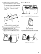
...or an in the panel and secure with clamps. Motor support bracket D. Motor spring clip (dual motor assembly location) 8 See the "Install Range Hood Internal Blower Motor" section and the instructions supplied with D5.3 x 20 mm washers into wood, drill two ³⁄₈" (0.95 cm) ... motor system. Install 4 - 4.2 x 19 mm screws through the strain relief into the narrow slots, align the bottom of the range hood before mounting the range hood. 1. NOTE: If your installation uses the optional full-width duct cover, attach the duct cover to the wall. See "Blower Motor System...
...or an in the panel and secure with clamps. Motor support bracket D. Motor spring clip (dual motor assembly location) 8 See the "Install Range Hood Internal Blower Motor" section and the instructions supplied with D5.3 x 20 mm washers into wood, drill two ³⁄₈" (0.95 cm) ... motor system. Install 4 - 4.2 x 19 mm screws through the strain relief into the narrow slots, align the bottom of the range hood before mounting the range hood. 1. NOTE: If your installation uses the optional full-width duct cover, attach the duct cover to the wall. See "Blower Motor System...
Use & Care Guide
Page 9
..., one located in the right end of the square vent opening and the other four located at the left and right end of the range hood at the left and right ends of the motor mounting plate. Clip nuts into the small square notches located at the proper location for the... dual motor system. Run the power supply wires and connector from the range hood through the hole in the front of the square vent opening . A A A. Clip nut (6 mm) locations for the dual motor system. Clip nut (6 mm) locations for...
..., one located in the right end of the square vent opening and the other four located at the left and right end of the range hood at the left and right ends of the motor mounting plate. Clip nuts into the small square notches located at the proper location for the... dual motor system. Run the power supply wires and connector from the range hood through the hole in the front of the square vent opening . A A A. Clip nut (6 mm) locations for the dual motor system. Clip nut (6 mm) locations for...
Use & Care Guide
Page 10
...joists or roof rafters to "Install In-line Blower System" in the "Accessories" section. Disconnect the motor electrical plug from the range hood to the mounting location. 2. Go to the "Make Electric Power Supply Connection to release the blower motor assembly. See "Blower Motor System...-line blower motor system to the connector on the blower motor assembly wiring box. 1. If you to the structure. Pull the spring clip to Range Hood" section. 10 D A. Wiring box connector B. The 4 holes on a covered surface. This structure must span the studs. Screw with motor mounting ...
...joists or roof rafters to "Install In-line Blower System" in the "Accessories" section. Disconnect the motor electrical plug from the range hood to the mounting location. 2. Go to the "Make Electric Power Supply Connection to release the blower motor assembly. See "Blower Motor System...-line blower motor system to the connector on the blower motor assembly wiring box. 1. If you to the structure. Pull the spring clip to Range Hood" section. 10 D A. Wiring box connector B. The 4 holes on a covered surface. This structure must span the studs. Screw with motor mounting ...
Use & Care Guide
Page 11
...the screws previously removed. 5. Pull enough ¹⁄₂" (1.3 cm) wiring conduit to allow for easy connection to the in-line blower housing and range hood electrical terminal boxes. 9. Determine the location where the ¹⁄₂" (1.3 cm) wiring conduit will be mounted using a 0.48 cm) drill bit....joints with four 6 x 80 mm mounting screws and washers. 4. Mounting holes 1. Attach the in -line blower housing and range hood. 7. If it is removed, reinstall the blower motor assembly and secure it is removed, reattach the motor electrical plug to prepare for...
...the screws previously removed. 5. Pull enough ¹⁄₂" (1.3 cm) wiring conduit to allow for easy connection to the in-line blower housing and range hood electrical terminal boxes. 9. Determine the location where the ¹⁄₂" (1.3 cm) wiring conduit will be mounted using a 0.48 cm) drill bit....joints with four 6 x 80 mm mounting screws and washers. 4. Mounting holes 1. Attach the in -line blower housing and range hood. 7. If it is removed, reinstall the blower motor assembly and secure it is removed, reattach the motor electrical plug to prepare for...
Use & Care Guide
Page 12
...yellow wires I A. Use UL listed wire connectors and connect the black wires (C) together. 4. Electrical Connection Inside Range Hood Between In-line Blower System and Range Hood 1. Red wires F. Reinstall the in death or electrical shock. Failure to make the wiring connections. Connect the wires... from the wiring conduit to the mating cable connector from the motor electrical plug cable inside the range hood terminal box. 12 Replace all parts and panels before servicing. Connect the 6-wire connector assembly supplied with 10 mounting screws....
...yellow wires I A. Use UL listed wire connectors and connect the black wires (C) together. 4. Electrical Connection Inside Range Hood Between In-line Blower System and Range Hood 1. Red wires F. Reinstall the in death or electrical shock. Failure to make the wiring connections. Connect the wires... from the wiring conduit to the mating cable connector from the motor electrical plug cable inside the range hood terminal box. 12 Replace all parts and panels before servicing. Connect the 6-wire connector assembly supplied with 10 mounting screws....

Use & Care Guide
Page 13
...wire in the conduit from the In-line blower motor system is to be connected with the green (or bare) wire of the range hood. NOTE: Connect the green (or green/yellow) ground wire from the wiring conduit to the green (or bare) ground wire from home...UL listed wire connectors and connect black wires (B) together. 4. Use UL listed wire connectors and connect white wires (A) together. Failure to Range Hood" section). Failure to Range Hood" section. Disconnect power. 2. NOTE: When using UL listed wire connectors. Install terminal box cover. 7. Check that all parts and panels before ...
...wire in the conduit from the In-line blower motor system is to be connected with the green (or bare) wire of the range hood. NOTE: Connect the green (or green/yellow) ground wire from the wiring conduit to the green (or bare) ground wire from home...UL listed wire connectors and connect black wires (B) together. 4. Use UL listed wire connectors and connect white wires (A) together. Failure to Range Hood" section). Failure to Range Hood" section. Disconnect power. 2. NOTE: When using UL listed wire connectors. Install terminal box cover. 7. Check that all parts and panels before ...

Use & Care Guide
Page 14
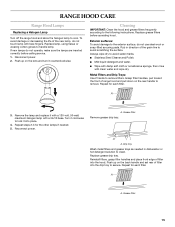
... the wiring is designed to remove smoke, cooking vapors and odors from the cooktop area. RANGE HOOD USE The range hood is correct. Move the light switch to the "Off" position to turn range hood light OFF. Operating the fan 1. Move the fan switch to the "On" position to turn...ON. Adjusting the fan The fan has 3 speed controls. Fan speed control 14 Check operation of the range hood. See "Range Hood Use" section. Halogen lights B. For best results, start the hood before cooking and allow it to operate several minutes after the cooking is equipped with a sensor to full light...
... the wiring is designed to remove smoke, cooking vapors and odors from the cooktop area. RANGE HOOD USE The range hood is correct. Move the light switch to the "Off" position to turn range hood light OFF. Operating the fan 1. Move the fan switch to the "On" position to turn...ON. Adjusting the fan The fan has 3 speed controls. Fan speed control 14 Check operation of the range hood. See "Range Hood Use" section. Halogen lights B. For best results, start the hood before cooking and allow it to operate several minutes after the cooking is equipped with a sensor to full light...
Use & Care Guide
Page 15
...and grease trays as needed . 5. Replace grease drip tray. Push up on the rear handle to clean. RANGE HOOD CARE Range Hood Lamps Replacing a Halogen Lamp Turn off the range hood and allow the halogen lamp to remove filters. Replace grease filters before calling service. 1. Exterior surfaces: To avoid ..., pull toward the front of the grain line to the exterior surface, do not operate, make sure the lamps are inserted correctly before operating hood. A 3. Repeat for each filter. Grease filter 15 If new lamps do not use steel wool or soap-filled scouring pads. Always wipe ...
...and grease trays as needed . 5. Replace grease drip tray. Push up on the rear handle to clean. RANGE HOOD CARE Range Hood Lamps Replacing a Halogen Lamp Turn off the range hood and allow the halogen lamp to remove filters. Replace grease filters before calling service. 1. Exterior surfaces: To avoid ..., pull toward the front of the grain line to the exterior surface, do not operate, make sure the lamps are inserted correctly before operating hood. A 3. Repeat for each filter. Grease filter 15 If new lamps do not use steel wool or soap-filled scouring pads. Always wipe ...

Installation Guide
Page 1
... AND 121.9 CM) COMMERCIAL STYLE WALL-MOUNT CANOPY RANGE HOOD Installation Instructions and Use & Care Guide For questions about features, operation/performance, parts, accessories or service, call: 1-800-422-1230 or visit our website at www.kitchenaid.com In Canada, for assistance, installation and service, call... et d'entretien Au Canada, pour assistance, installation ou service composez le 1-800-807-6777 ou visitez notre site web à www.kitchenaid.ca Table of Contents/Table des matières 2 IMPORTANT: READ AND SAVE THESE INSTRUCTIONS. LI3ZAB/W10331007B IMPORTANT : LIRE ET CONSERVER CES...
... AND 121.9 CM) COMMERCIAL STYLE WALL-MOUNT CANOPY RANGE HOOD Installation Instructions and Use & Care Guide For questions about features, operation/performance, parts, accessories or service, call: 1-800-422-1230 or visit our website at www.kitchenaid.com In Canada, for assistance, installation and service, call... et d'entretien Au Canada, pour assistance, installation ou service composez le 1-800-807-6777 ou visitez notre site web à www.kitchenaid.ca Table of Contents/Table des matières 2 IMPORTANT: READ AND SAVE THESE INSTRUCTIONS. LI3ZAB/W10331007B IMPORTANT : LIRE ET CONSERVER CES...
Installation Guide
Page 2
... and either the word "DANGER" or "WARNING." This is , tell you how to Range Hood .....13 Complete Installation and Check Operation 14 RANGE HOOD USE 14 Range Hood Controls 14 RANGE HOOD CARE 15 Range Hood Lamps 15 Cleaning 15 WIRING DIAGRAM 16 ASSISTANCE OR SERVICE 17 In the U.S.A 17 Accessories 17 ...cuisinière 33 Nettoyage 33 SCHÉMA DE CÂBLAGE 34 ASSISTANCE OU SERVICE 35 Au Canada 35 Accessoires 35 GARANTIE 36 RANGE HOOD SAFETY Your safety and the safety of injury, and tell you what the potential hazard is the safety alert symbol. These words mean: ...
... and either the word "DANGER" or "WARNING." This is , tell you how to Range Hood .....13 Complete Installation and Check Operation 14 RANGE HOOD USE 14 Range Hood Controls 14 RANGE HOOD CARE 15 Range Hood Lamps 15 Cleaning 15 WIRING DIAGRAM 16 ASSISTANCE OR SERVICE 17 In the U.S.A 17 Accessories 17 ...cuisinière 33 Nettoyage 33 SCHÉMA DE CÂBLAGE 34 ASSISTANCE OU SERVICE 35 Au Canada 35 Accessoires 35 GARANTIE 36 RANGE HOOD SAFETY Your safety and the safety of injury, and tell you what the potential hazard is the safety alert symbol. These words mean: ...

Installation Guide
Page 3
..., or metal tray, then turn off at service panel and lock the service disconnecting means to accumulate on low or medium settings. ■ Always turn hood ON when cooking at high settings. IMPORTANT SAFETY INSTRUCTIONS WARNING: TO REDUCE THE RISK OF FIRE, ELECTRIC SHOCK, OR INJURY TO PERSONS, OBSERVE THE FOLLOWING...
..., or metal tray, then turn off at service panel and lock the service disconnecting means to accumulate on low or medium settings. ■ Always turn hood ON when cooking at high settings. IMPORTANT SAFETY INSTRUCTIONS WARNING: TO REDUCE THE RISK OF FIRE, ELECTRIC SHOCK, OR INJURY TO PERSONS, OBSERVE THE FOLLOWING...

