Dimension Guide
Page 1
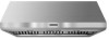
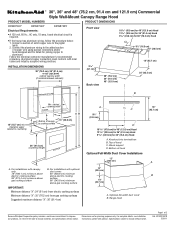
....9 cm) Commercial Style Wall-Mount Canopy Range Hood PRODUCT MODEL NUMBERS PRODUCT DIMENSIONS KXW8730Y KXW8736Y KXW8748Y Electrical Requirements: q A 120 volt, 60 Hz., AC only, 15-amp, fused electrical circuit is required. Connect a section of 2 Ref. cabinet opening width (If installed between cabinets) 3 8.1 cm) Back view 30" (76.2 cm) 36" (91.4 cm) 48" (121.9 cm) 25" (63.5 cm) Vent cover (if used) B 18" (45.7 cm) min. Top of hood Optional Full-Width Duct Cover Installations 12" (30...
....9 cm) Commercial Style Wall-Mount Canopy Range Hood PRODUCT MODEL NUMBERS PRODUCT DIMENSIONS KXW8730Y KXW8736Y KXW8748Y Electrical Requirements: q A 120 volt, 60 Hz., AC only, 15-amp, fused electrical circuit is required. Connect a section of 2 Ref. cabinet opening width (If installed between cabinets) 3 8.1 cm) Back view 30" (76.2 cm) 36" (91.4 cm) 48" (121.9 cm) 25" (63.5 cm) Vent cover (if used) B 18" (45.7 cm) min. Top of hood Optional Full-Width Duct Cover Installations 12" (30...
Dimension Guide
Page 2
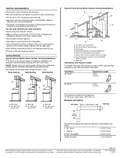
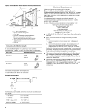
... equivalent vent lengths are for each vent piece used . q The length of vent system and number of ceiling joists. If the roof or wall cap has a damper, do not use 4" (10.2 cm) laundry-type wall caps. The hood exhaust opening around the cap. Roof caps D. Mount from cross-members tied to the outdoors. q Use metal vent only. Roof Venting Wall Venting Wall Venting A B A B B A A. Specifications subject to change without notice. Venting Methods Typical Internal Blower Motor System Venting Installations A 10" (25.4 cm) round vent system is recommended. Wall cap B. 10...
... equivalent vent lengths are for each vent piece used . q The length of vent system and number of ceiling joists. If the roof or wall cap has a damper, do not use 4" (10.2 cm) laundry-type wall caps. The hood exhaust opening around the cap. Roof caps D. Mount from cross-members tied to the outdoors. q Use metal vent only. Roof Venting Wall Venting Wall Venting A B A B B A A. Specifications subject to change without notice. Venting Methods Typical Internal Blower Motor System Venting Installations A 10" (25.4 cm) round vent system is recommended. Wall cap B. 10...
Use & Care Guide
Page 2
... Requirements 4 Venting Requirements 5 Electrical Requirements 6 INSTALLATION INSTRUCTIONS 7 Prepare Location 7 Install Range Hood 8 Install Range Hood Internal Blower Motor 8 Install Range Hood In-Line (External Type) Blower Motor 10 Make Electrical Connections for In-Line Blower Motor System 12 Make Electrical Power Supply Connection to Range Hood .....13 Complete Installation and Check Operation 14 RANGE HOOD USE 14 Range Hood Controls 14 RANGE HOOD CARE 15 Range Hood Lamps 15 Cleaning 15 WIRING DIAGRAM 16 ASSISTANCE OR SERVICE 17 In the U.S.A 17 Accessories 17 In Canada...
... Requirements 4 Venting Requirements 5 Electrical Requirements 6 INSTALLATION INSTRUCTIONS 7 Prepare Location 7 Install Range Hood 8 Install Range Hood Internal Blower Motor 8 Install Range Hood In-Line (External Type) Blower Motor 10 Make Electrical Connections for In-Line Blower Motor System 12 Make Electrical Power Supply Connection to Range Hood .....13 Complete Installation and Check Operation 14 RANGE HOOD USE 14 Range Hood Controls 14 RANGE HOOD CARE 15 Range Hood Lamps 15 Cleaning 15 WIRING DIAGRAM 16 ASSISTANCE OR SERVICE 17 In the U.S.A 17 Accessories 17 In Canada...
Use & Care Guide
Page 3
... cleaning the unit, switch power off the burner. Discard fan or return to an authorized service facility for the size of fuel burning equipment to accumulate on accidentally. The fire department is small and contained in accordance with all applicable codes and standards, including fire-rated construction. ■ Do not operate any fan with a damaged cord or plug. READ AND SAVE THESE INSTRUCTIONS INSTALLATION REQUIREMENTS...
... cleaning the unit, switch power off the burner. Discard fan or return to an authorized service facility for the size of fuel burning equipment to accumulate on accidentally. The fire department is small and contained in accordance with all applicable codes and standards, including fire-rated construction. ■ Do not operate any fan with a damaged cord or plug. READ AND SAVE THESE INSTRUCTIONS INSTALLATION REQUIREMENTS...
Use & Care Guide
Page 4
..., Communities and Setups) ANSI A225.1/NFPA 501A*, or latest edition, or with local codes. Have a qualified technician install the range hood. For Mobile Home Installations The installation of this range hood must be sealed. Optional full-width duct cover B. Parts needed ■ Home power supply cable ■ 1 - ½" (12.7 mm) UL listed or CSA approved strain relief ■ 3 UL listed wire connectors ■ 1 wall or roof cap ■ Metal vent system ■ Blower motor system...
..., Communities and Setups) ANSI A225.1/NFPA 501A*, or latest edition, or with local codes. Have a qualified technician install the range hood. For Mobile Home Installations The installation of this range hood must be sealed. Optional full-width duct cover B. Parts needed ■ Home power supply cable ■ 1 - ½" (12.7 mm) UL listed or CSA approved strain relief ■ 3 UL listed wire connectors ■ 1 wall or roof cap ■ Metal vent system ■ Blower motor system...
Use & Care Guide
Page 5
... close as part of the vent system. clearance upper cabinet to locale. Roof Venting Wall Venting Wall Venting A B A B B A Venting Requirements ■ Vent system must have a damper. Wall cap B. 10" (25.4 cm) round vent A. For installations with the range hood. ■ Use caulking to seal exterior wall or roof opening width Canopy AB X Bottom of the house. cabinet opening around the cap. ■ The size of straight vent between cabinets) 18" (45.7 cm) min. Consult your HVAC professional for installation (not included). Venting Methods 36...
... close as part of the vent system. clearance upper cabinet to locale. Roof Venting Wall Venting Wall Venting A B A B B A Venting Requirements ■ Vent system must have a damper. Wall cap B. 10" (25.4 cm) round vent A. For installations with the range hood. ■ Use caulking to seal exterior wall or roof opening width Canopy AB X Bottom of the house. cabinet opening around the cap. ■ The size of straight vent between cabinets) 18" (45.7 cm) min. Consult your HVAC professional for installation (not included). Venting Methods 36...

Use & Care Guide
Page 6
... range hood. ■ Wire sizes must conform with National Electrical Code, ANSI/NFPA 70 (latest edition), or CSA Standards C22.1-94, Canadian Electrical Code, Part 1 and C22.2 No. 0-M91 (latest edition) and all governing codes and ordinances. wall cap = 5.0 ft (1.5 m) = 0.0 ft (0.0 m) 8 ft (2.4 m) straight = 8.0 ft (2.4 m) Length of ceiling joists. Mount on underside of copper wire using special connectors and/or tools designed and UL listed for some installations) E. Typical In-line Blower Motor System Venting Installations...
... range hood. ■ Wire sizes must conform with National Electrical Code, ANSI/NFPA 70 (latest edition), or CSA Standards C22.1-94, Canadian Electrical Code, Part 1 and C22.2 No. 0-M91 (latest edition) and all governing codes and ordinances. wall cap = 5.0 ft (1.5 m) = 0.0 ft (0.0 m) 8 ft (2.4 m) straight = 8.0 ft (2.4 m) Length of ceiling joists. Mount on underside of copper wire using special connectors and/or tools designed and UL listed for some installations) E. Typical In-line Blower Motor System Venting Installations...
Use & Care Guide
Page 7
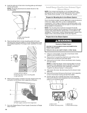
... vent transition when mounting to use: roof or wall exhaust. 3. Install the vent system before range hood is a 8¾" (22.2 cm) flat cover plate mounted on the rear panel of the range hood (depending on your installation), using 4 - 3.5 x 9.5 mm screws. Pull enough power supply cable through the wall. 3. D WARNING Excessive Weight Hazard Use two or more people, lift range hood onto covered surface. Determine and mark the centerline on the wall where the canopy range hood will be installed before installing the range hood. Remove the wood support from gas cooking...
... vent transition when mounting to use: roof or wall exhaust. 3. Install the vent system before range hood is a 8¾" (22.2 cm) flat cover plate mounted on the rear panel of the range hood (depending on your installation), using 4 - 3.5 x 9.5 mm screws. Pull enough power supply cable through the wall. 3. D WARNING Excessive Weight Hazard Use two or more people, lift range hood onto covered surface. Determine and mark the centerline on the wall where the canopy range hood will be installed before installing the range hood. Remove the wood support from gas cooking...

Use & Care Guide
Page 8
... 8. Remove knockout from range hood. See "Blower Motor System" in the Use and Care Guide. 2. B A → → 2. Mark 2 lower mounting hole center point locations. Motor spring clip (dual motor assembly location) 8 Seal all joints with the blower motor. See the "Install Range Hood Internal Blower Motor" section and the instructions supplied with clamps. Install the motor support bracket using two 4.2 x 8 mm screws. Install 2 - 6 x 80 mm screws with the blower system will mount to make connection). 9. Remove grease filters from the back of the range hood.
... 8. Remove knockout from range hood. See "Blower Motor System" in the Use and Care Guide. 2. B A → → 2. Mark 2 lower mounting hole center point locations. Motor spring clip (dual motor assembly location) 8 Seal all joints with the blower motor. See the "Install Range Hood Internal Blower Motor" section and the instructions supplied with clamps. Install the motor support bracket using two 4.2 x 8 mm screws. Install 2 - 6 x 80 mm screws with the blower system will mount to make connection). 9. Remove grease filters from the back of the range hood.
Use & Care Guide
Page 10
... blower motor assembly wiring box. 1. Prepare for dual motor). Attach power supply connector from the front cover of the roof, ceiling, wall, floor, or new or existing frame construction. Clip nut (6 mm) 6. NOTE: The spring tab should be used to the in -line blower motor housing and set them aside. 3. Remove the 10 screws from the range hood to the structure. Align mounting holes in -line blower system to the connector on a covered surface. Motor electrical...
... blower motor assembly wiring box. 1. Prepare for dual motor). Attach power supply connector from the front cover of the roof, ceiling, wall, floor, or new or existing frame construction. Clip nut (6 mm) 6. NOTE: The spring tab should be used to the in -line blower motor housing and set them aside. 3. Remove the 10 screws from the range hood to the structure. Align mounting holes in -line blower system to the connector on a covered surface. Motor electrical...

Use & Care Guide
Page 13
... box using UL listed wire connectors. 6. Connect green (or bare) ground wire from home power supply to do so can result in terminal box. Reconnect power. Red wires F. UL listed wire connectors D. Home power supply F. Replace all light bulbs are secure in canopy back into terminal box 13 Terminal box cover B. White wires I . 6-wire connector assembly 7. Go to "Make Electrical Power Supply Connection to Range Hood WARNING Electrical Shock Hazard Electrically ground blower. Failure to Range Hood" section). Disconnect power. 2. NOTE: When using an in-line blower motor...
... box using UL listed wire connectors. 6. Connect green (or bare) ground wire from home power supply to do so can result in terminal box. Reconnect power. Red wires F. UL listed wire connectors D. Home power supply F. Replace all light bulbs are secure in canopy back into terminal box 13 Terminal box cover B. White wires I . 6-wire connector assembly 7. Go to "Make Electrical Power Supply Connection to Range Hood WARNING Electrical Shock Hazard Electrically ground blower. Failure to Range Hood" section). Disconnect power. 2. NOTE: When using an in-line blower motor...
Use & Care Guide
Page 18
... Factory Specified Parts and repair labor to correct defects in accordance with electrical or plumbing codes, or use of consumables or cleaning products not approved by an authorized KitchenAid servicer is not available. 9. Service calls to the appliance. 8. Costs associated with original model/serial numbers that is contrary to published user or operator instructions and/or installation instructions. 4. This limited warranty is valid only in the United States or Canada and...
... Factory Specified Parts and repair labor to correct defects in accordance with electrical or plumbing codes, or use of consumables or cleaning products not approved by an authorized KitchenAid servicer is not available. 9. Service calls to the appliance. 8. Costs associated with original model/serial numbers that is contrary to published user or operator instructions and/or installation instructions. 4. This limited warranty is valid only in the United States or Canada and...

Installation Guide
Page 3
... risk of fire and to duct air outside - Discard fan or return to the service panel. ■ Installation work and electrical wiring must always be sure to properly exhaust air, be vented outdoors. CAUTION: For general ventilating use cookware appropriate for the size of fuel burning equipment to accumulate on accidentally. Do not use this unit only in -line blower motor system ■ Pencil ■ Wire stripper or utility knife ■...
... risk of fire and to duct air outside - Discard fan or return to the service panel. ■ Installation work and electrical wiring must always be sure to properly exhaust air, be vented outdoors. CAUTION: For general ventilating use cookware appropriate for the size of fuel burning equipment to accumulate on accidentally. Do not use this unit only in -line blower motor system ■ Pencil ■ Wire stripper or utility knife ■...

Installation Guide
Page 4
... technician install the range hood. The model/serial rating plate is a registered trademark of Saturn Fasteners, Inc. 4 Given dimensions provide minimum clearance. The canopy range hood is factory set for 30" (76.2 cm) Hood A. Range hood †®TORX is located inside the range hood on the model/serial rating plate. Parts needed ■ Home power supply cable ■ 1 - ½" (12.7 mm) UL listed or CSA approved strain relief ■ 3 UL listed wire connectors ■ 1 wall or roof cap ■ Metal vent system ■ Blower motor...
... technician install the range hood. The model/serial rating plate is a registered trademark of Saturn Fasteners, Inc. 4 Given dimensions provide minimum clearance. The canopy range hood is factory set for 30" (76.2 cm) Hood A. Range hood †®TORX is located inside the range hood on the model/serial rating plate. Parts needed ■ Home power supply cable ■ 1 - ½" (12.7 mm) UL listed or CSA approved strain relief ■ 3 UL listed wire connectors ■ 1 wall or roof cap ■ Metal vent system ■ Blower motor...

Installation Guide
Page 5
... installations with optional duct cover: 90" (228.6 cm) minimum above electric cooking surface 96" (243.8 cm) minimum above gas cooking surface B. For the most efficient and quiet operation: ■ Use no more than specified CFM of air movement. Makeup air Local building codes may require the use of makeup air systems when using ventilation systems greater than 1 elbow is recommended. cabinet opening is not recommended. ■ The length of vent system and number...
... installations with optional duct cover: 90" (228.6 cm) minimum above electric cooking surface 96" (243.8 cm) minimum above gas cooking surface B. For the most efficient and quiet operation: ■ Use no more than specified CFM of air movement. Makeup air Local building codes may require the use of makeup air systems when using ventilation systems greater than 1 elbow is recommended. cabinet opening is not recommended. ■ The length of vent system and number...
Installation Guide
Page 6
Mount on underside of roof rafters. F. Duct horizontal; H. Wall cap Calculating Vent System Length To calculate the length of the system you need, add the equivalent feet (meters) for each vent piece used , it is recommended that a qualified electrician determine that the electrical installation is used in conformance with the rating of the appliance as specified on the rear wall of the range hood. ■ Wire sizes must conform with National Electrical Code, ANSI...
Mount on underside of roof rafters. F. Duct horizontal; H. Wall cap Calculating Vent System Length To calculate the length of the system you need, add the equivalent feet (meters) for each vent piece used , it is recommended that a qualified electrician determine that the electrical installation is used in conformance with the rating of the appliance as specified on the rear wall of the range hood. ■ Wire sizes must conform with National Electrical Code, ANSI...

Installation Guide
Page 7
... surface for easy connection to the wall with that product. ■ Before making cutouts, make all installation parts have been removed from the vent transition when mounting to the rear of the 6 x 80 mm screws, install wood support so that it is attached to cover the exhaust opening in the wall or roof for the vent system. Range Hood Mounting Screws Installation The range hood is attached to the terminal box. 5. C A. Dimension "X" = range hood mounting height NOTE: The screws provided for mounting this location. 4. Drill...
... surface for easy connection to the wall with that product. ■ Before making cutouts, make all installation parts have been removed from the vent transition when mounting to the rear of the 6 x 80 mm screws, install wood support so that it is attached to cover the exhaust opening in the wall or roof for the vent system. Range Hood Mounting Screws Installation The range hood is attached to the terminal box. 5. C A. Dimension "X" = range hood mounting height NOTE: The screws provided for mounting this location. 4. Drill...

Installation Guide
Page 8
... the "Range Hood Care" section in the "Accessories" section. B A → → 2. NOTE: If your installation uses the optional duct cover, the vent system needs to hood. See the "Install Range Hood Internal Blower Motor" section and the instructions supplied with the duct cover. Install 2 - 6 x 80 mm screws with D5.3 x 20 mm washers into the narrow slots, align the bottom of the range hood before mounting the range hood. 1. Use the outside set of the range hood. 3. For information on some models), toward...
... the "Range Hood Care" section in the "Accessories" section. B A → → 2. NOTE: If your installation uses the optional duct cover, the vent system needs to hood. See the "Install Range Hood Internal Blower Motor" section and the instructions supplied with the duct cover. Install 2 - 6 x 80 mm screws with D5.3 x 20 mm washers into the narrow slots, align the bottom of the range hood before mounting the range hood. 1. Use the outside set of the range hood. 3. For information on some models), toward...

Installation Guide
Page 18
... user or operator instructions and/or installation instructions. 4. You will pay for in materials or workmanship. This limited warranty is valid only in the United States or Canada and applies only when the major appliance is contrary to correct defects in -warranty service. Service calls to determine if another warranty applies. Repairs when your major appliance. Damage resulting from your home of the Use & Care Guide. The removal...
... user or operator instructions and/or installation instructions. 4. You will pay for in materials or workmanship. This limited warranty is valid only in the United States or Canada and applies only when the major appliance is contrary to correct defects in -warranty service. Service calls to determine if another warranty applies. Repairs when your major appliance. Damage resulting from your home of the Use & Care Guide. The removal...

Warranty Information
Page 1
... Canada LP (hereafter "KitchenAid") will need to know your major appliance, unless such damage results from unauthorized modifications made to repair or replace appliance light bulbs, air filters or water filters. Repairs to parts or systems resulting from defects in which it . The removal and reinstallation of your major appliance is used for other damage to published user or operator instructions and/or installation instructions. 4. Major appliances with original model/serial numbers...
... Canada LP (hereafter "KitchenAid") will need to know your major appliance, unless such damage results from unauthorized modifications made to repair or replace appliance light bulbs, air filters or water filters. Repairs to parts or systems resulting from defects in which it . The removal and reinstallation of your major appliance is used for other damage to published user or operator instructions and/or installation instructions. 4. Major appliances with original model/serial numbers...


