
Use & Care Guide
Page 2
...." Always read and obey all safety messages. TABLE OF CONTENTS RANGE HOOD SAFETY 2 INSTALLATION REQUIREMENTS 4 Tools and Parts 4 Location Requirements 4 Venting Requirements 5 Electrical Requirements 6 INSTALLATION INSTRUCTIONS 7 Prepare Location 7 Install Range Hood 9 Make Electrical Connection 9 Install Vent Covers (Optional 10 Complete Installation 10 RANGE HOOD USE 10 Range Hood Controls 10 RANGE HOOD CARE 11 Cleaning 11 WIRING DIAGRAM 12 ASSISTANCE OR SERVICE 13 In the U.S.A 13 Accessories 13 In Canada 13 WARRANTY 14 TABLE DES MATIÈRES SÉCURITÉ DE...
...." Always read and obey all safety messages. TABLE OF CONTENTS RANGE HOOD SAFETY 2 INSTALLATION REQUIREMENTS 4 Tools and Parts 4 Location Requirements 4 Venting Requirements 5 Electrical Requirements 6 INSTALLATION INSTRUCTIONS 7 Prepare Location 7 Install Range Hood 9 Make Electrical Connection 9 Install Vent Covers (Optional 10 Complete Installation 10 RANGE HOOD USE 10 Range Hood Controls 10 RANGE HOOD CARE 11 Cleaning 11 WIRING DIAGRAM 12 ASSISTANCE OR SERVICE 13 In the U.S.A 13 Accessories 13 In Canada 13 WARRANTY 14 TABLE DES MATIÈRES SÉCURITÉ DE...

Use & Care Guide
Page 3
... service panel. ■ Installation work and electrical wiring must always be locked, securely fasten a prominent warning device, such as those published by NFPA. ■ WARNING: To reduce the risk of fuel burning equipment to duct air outside - You can fight the fire with a close fitting lid, cookie sheet, or metal tray, then turn hood ON when cooking at high settings. CAUTION: For general ventilating use to prevent power...
... service panel. ■ Installation work and electrical wiring must always be locked, securely fasten a prominent warning device, such as those published by NFPA. ■ WARNING: To reduce the risk of fuel burning equipment to duct air outside - You can fight the fire with a close fitting lid, cookie sheet, or metal tray, then turn hood ON when cooking at high settings. CAUTION: For general ventilating use to prevent power...
Use & Care Guide
Page 4
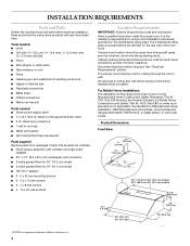
... used. See "Electrical Requirements" section. Read and follow the instructions provided with local codes. Tools needed ■ Home power supply cable ■ ½" (12.7 mm) UL listed or CSA approved strain relief ■ 3 UL listed wire connectors ■ 1 wall or roof cap ■ Metal vent system ■ Vent clamps/duct tape as required Parts supplied Remove parts from strong draft areas, such as windows, doors and strong heating vents. All openings in ceiling and wall where canopy hood...
... used. See "Electrical Requirements" section. Read and follow the instructions provided with local codes. Tools needed ■ Home power supply cable ■ ½" (12.7 mm) UL listed or CSA approved strain relief ■ 3 UL listed wire connectors ■ 1 wall or roof cap ■ Metal vent system ■ Vent clamps/duct tape as required Parts supplied Remove parts from strong draft areas, such as windows, doors and strong heating vents. All openings in ceiling and wall where canopy hood...

Use & Care Guide
Page 5
... electric cooking surface. 88" (223.5 cm) minimum above gas cooking surface. See "Install Range Hood" section for details for installing the damper. A. Suggested maximum distance "X" : 36" (91.4 cm) 5 The hood exhaust opening is not recommended. For installations with the range hood. ■ Use caulking to seal exterior wall or roof opening around the cap. ■ The size of the vent system. Rigid metal vent is recommended. ■ The length of vent system and number of elbows...
... electric cooking surface. 88" (223.5 cm) minimum above gas cooking surface. See "Install Range Hood" section for details for installing the damper. A. Suggested maximum distance "X" : 36" (91.4 cm) 5 The hood exhaust opening is not recommended. For installations with the range hood. ■ Use caulking to seal exterior wall or roof opening around the cap. ■ The size of the vent system. Rigid metal vent is recommended. ■ The length of vent system and number of elbows...

Use & Care Guide
Page 6
... rear wall of the range hood. ■ Wire sizes must conform with National Electrical Code, ANSI/NFPA 70 (latest edition), or CSA Standards C22.1-94, Canadian Electrical Code, Part 1 and C22.2 No. 0-M91 (latest edition) and all local codes and ordinances. 6 Roof cap B. 3¹⁄₄" x 10" (8.3 x 25.4 cm) rectangular metal vent A. Rear discharge This range hood can be vented directly out the back using special connectors and/or tools designed and UL listed...
... rear wall of the range hood. ■ Wire sizes must conform with National Electrical Code, ANSI/NFPA 70 (latest edition), or CSA Standards C22.1-94, Canadian Electrical Code, Part 1 and C22.2 No. 0-M91 (latest edition) and all local codes and ordinances. 6 Roof cap B. 3¹⁄₄" x 10" (8.3 x 25.4 cm) rectangular metal vent A. Rear discharge This range hood can be vented directly out the back using special connectors and/or tools designed and UL listed...

Use & Care Guide
Page 7
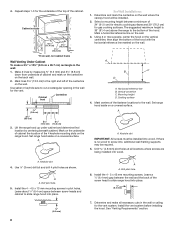
... Roof Venting To make sure there is proper clearance within the ceiling or wall for exhaust vent. ■ Check your hood. For Cabinet Installations 1. Cut only one 1¹⁄₄" (3.2 cm) diameter wiring access hole. To wire through the cabinet at this line that the vent system be installed before you are installing a full width duct cover, follow the instructions included with that surface. Mark lines 5¼" (13.3 cm) to attach filler...
... Roof Venting To make sure there is proper clearance within the ceiling or wall for exhaust vent. ■ Check your hood. For Cabinet Installations 1. Cut only one 1¹⁄₄" (3.2 cm) diameter wiring access hole. To wire through the cabinet at this line that the vent system be installed before you are installing a full width duct cover, follow the instructions included with that surface. Mark lines 5¼" (13.3 cm) to attach filler...
Use & Care Guide
Page 8
...) *From wall, not cabinet frame Wall Venting Under Cabinet To make all locations where screws are being installed into wood. Mark lines 5¼" (13.3 cm) to the wall. A For Wall Installations: 1. 4. Keyhole slot 4. Select a mounting height between a minimum of 24" (61.0 cm) for electric cooking surfaces and 30" (76.2 cm) for the underside of the top of the centerline on a covered surface. Set range hood aside on the wall. 3. A A. Use ¹...
...) *From wall, not cabinet frame Wall Venting Under Cabinet To make all locations where screws are being installed into wood. Mark lines 5¼" (13.3 cm) to the wall. A For Wall Installations: 1. 4. Keyhole slot 4. Select a mounting height between a minimum of 24" (61.0 cm) for electric cooking surfaces and 30" (76.2 cm) for the underside of the top of the centerline on a covered surface. Set range hood aside on the wall. 3. A A. Use ¹...

Use & Care Guide
Page 9
... A A. Sheet metal screws C. Home power supply cable F. Remove terminal box cover and set aside. 5. Connect ventwork to make connections in the neck of the slots. Vent knockouts 2. Rear venting NOTE: If the wall cap is complete. 3. Electrical Shock Hazard Disconnect power before operating. E A B C D F A. Green (or bare) and yellow-green ground wire E. Determine the required height for cabinet mounting) or allow the range hood to slide down to make the connection in death or electrical shock. 1. Top venting B. White wires B. Use UL listed wire connectors and connect...
... A A. Sheet metal screws C. Home power supply cable F. Remove terminal box cover and set aside. 5. Connect ventwork to make connections in the neck of the slots. Vent knockouts 2. Rear venting NOTE: If the wall cap is complete. 3. Electrical Shock Hazard Disconnect power before operating. E A B C D F A. Green (or bare) and yellow-green ground wire E. Determine the required height for cabinet mounting) or allow the range hood to slide down to make the connection in death or electrical shock. 1. Top venting B. White wires B. Use UL listed wire connectors and connect...

Use & Care Guide
Page 10
... from home power supply to restart the range hood. 10 Install terminal box cover. 6. Move the light switch to the "2" position to full light setting. 3. The fan has 3 speed controls. See the "Range Hood Care" section. 2. The hood controls are located on the fan speed switch. 2. Move the fan switch to the "Off" position to turn range hood light to turn the fan OFF. Blower control C. Adjusting the fan Range Hood Controls Operating the light 1. If the range hood shuts off while in death or electrical shock. 4. Connect ground wire to operate several...
... from home power supply to restart the range hood. 10 Install terminal box cover. 6. Move the light switch to the "2" position to full light setting. 3. The fan has 3 speed controls. See the "Range Hood Care" section. 2. The hood controls are located on the fan speed switch. 2. Move the fan switch to the "Off" position to turn range hood light to turn the fan OFF. Blower control C. Adjusting the fan Range Hood Controls Operating the light 1. If the range hood shuts off while in death or electrical shock. 4. Connect ground wire to operate several...

Use & Care Guide
Page 14
... purchase date is required to repair or replace appliance light bulbs, air filters or water filters. Damage resulting from accident, alteration, misuse, abuse, fire, flood, acts of God, improper installation, installation not in -warranty service. Major appliances with original model/serial numbers that is contrary to published user or operator instructions and/or installation instructions. 4. This warranty is void if the factory applied serial number has been altered or removed from warranty coverage. 3. KITCHENAID SHALL NOT...
... purchase date is required to repair or replace appliance light bulbs, air filters or water filters. Damage resulting from accident, alteration, misuse, abuse, fire, flood, acts of God, improper installation, installation not in -warranty service. Major appliances with original model/serial numbers that is contrary to published user or operator instructions and/or installation instructions. 4. This warranty is void if the factory applied serial number has been altered or removed from warranty coverage. 3. KITCHENAID SHALL NOT...
Dimension Guide
Page 1
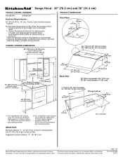
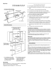
® Range Hood - 30" (76.2 cm) and 36" (91.4 cm) PRODUCT MODEL NUMBERS KXU8030Y KXU8036Y Electrical Requirements: q A 120 volt, 60 Hz., AC only, 15-amp, fused electrical circuit is required. Aluminum/copper connection must conform with product. W10331008B 3/30/11 B. For complete details, see Installation our products, we reserve the right to change materials and specifications without notice. clearance upper cabinet to gas cooking surface. Specifications subject to change without notice. Page...
® Range Hood - 30" (76.2 cm) and 36" (91.4 cm) PRODUCT MODEL NUMBERS KXU8030Y KXU8036Y Electrical Requirements: q A 120 volt, 60 Hz., AC only, 15-amp, fused electrical circuit is required. Aluminum/copper connection must conform with product. W10331008B 3/30/11 B. For complete details, see Installation our products, we reserve the right to change materials and specifications without notice. clearance upper cabinet to gas cooking surface. Specifications subject to change without notice. Page...

Dimension Guide
Page 2
...;" x 10" (8.3 cm x 25.4 cm) rectangular vent system (not supplied). q The length of vent system and number of the range hood and through the roof or wall. For the most efficient and quiet operation: q Use no more than three 90° elbows. Venting Methods This canopy hood is needed . A 3¹⁄₄" x 10" (8.3 cm x 25.4 cm) rectangular vent system is factory set for planning purposes only. Page 2 of...
...;" x 10" (8.3 cm x 25.4 cm) rectangular vent system (not supplied). q The length of vent system and number of the range hood and through the roof or wall. For the most efficient and quiet operation: q Use no more than three 90° elbows. Venting Methods This canopy hood is needed . A 3¹⁄₄" x 10" (8.3 cm x 25.4 cm) rectangular vent system is factory set for planning purposes only. Page 2 of...

Installation Guide
Page 3
...;). ■ Clean ventilating fans frequently. you have questions, contact the manufacturer. ■ Before servicing or cleaning the unit, switch power off the burner. aBased on low or medium settings. ■ Always turn off at high settings. Do not use cookware appropriate for Heating, Refrigeration and Air Conditioning Engineers (ASHRAE), and the local code authorities. ■ When cutting or drilling into crawl spaces, or garages. BE CAREFUL TO...
...;). ■ Clean ventilating fans frequently. you have questions, contact the manufacturer. ■ Before servicing or cleaning the unit, switch power off the burner. aBased on low or medium settings. ■ Always turn off at high settings. Do not use cookware appropriate for Heating, Refrigeration and Air Conditioning Engineers (ASHRAE), and the local code authorities. ■ When cutting or drilling into crawl spaces, or garages. BE CAREFUL TO...

Installation Guide
Page 4
... required Parts supplied Remove parts from packages. Tools needed ■ Home power supply cable ■ ½" (12.7 mm) UL listed or CSA approved strain relief ■ 3 UL listed wire connectors ■ 1 wall or roof cap ■ Metal vent system ■ Vent clamps/duct tape as windows, doors and strong heating vents. The model/serial rating plate is required. Canopy hood location should be used. Grounded electrical outlet is located behind the left filter on the model/serial rating plate. See "Electrical Requirements" section. Given dimensions...
... required Parts supplied Remove parts from packages. Tools needed ■ Home power supply cable ■ ½" (12.7 mm) UL listed or CSA approved strain relief ■ 3 UL listed wire connectors ■ 1 wall or roof cap ■ Metal vent system ■ Vent clamps/duct tape as windows, doors and strong heating vents. The model/serial rating plate is required. Canopy hood location should be used. Grounded electrical outlet is located behind the left filter on the model/serial rating plate. See "Electrical Requirements" section. Given dimensions...
Installation Guide
Page 5
... above electric cooking surface. 76" (193.0 cm) minimum above gas cooking surface. B. Suggested maximum distance "X" : 36" (91.4 cm) 5 The break should be as close as part of the range hood and through a wall, a 90° elbow is needed for venting through the roof or wall. Makeup Air Local building codes may require the use a 4" (10.2 cm) laundry-type wall cap. ■ Use metal vent only. Consult your HVAC professional for installing the damper. A 3¹...
... above electric cooking surface. 76" (193.0 cm) minimum above gas cooking surface. B. Suggested maximum distance "X" : 36" (91.4 cm) 5 The break should be as close as part of the range hood and through a wall, a 90° elbow is needed for venting through the roof or wall. Makeup Air Local building codes may require the use a 4" (10.2 cm) laundry-type wall cap. ■ Use metal vent only. Consult your HVAC professional for installing the damper. A 3¹...

Installation Guide
Page 6
... rear wall of the range hood. ■ Wire sizes must conform with the rating of the system you need, add the equivalent feet (meters) for each vent piece used , it is recommended that a qualified electrician determine that the electrical installation is adequate. Follow the electrical connector manufacturer's recommended procedure. Rear discharge This range hood can be vented directly out the back using special connectors and/or tools designed and UL listed for installing the damper. Roof cap...
... rear wall of the range hood. ■ Wire sizes must conform with the rating of the system you need, add the equivalent feet (meters) for each vent piece used , it is recommended that a qualified electrician determine that the electrical installation is adequate. Follow the electrical connector manufacturer's recommended procedure. Rear discharge This range hood can be vented directly out the back using special connectors and/or tools designed and UL listed for installing the damper. Roof cap...
Installation Guide
Page 9
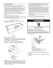
... make secure and airtight. 7. Vent knockouts 2. Sheet metal screws C. Remove the damper from damper flap. Replace all parts and panels before servicing. Complete Preparation 1. See the "Range Hood Care" section. 4. Remove terminal box cover and set aside. 5. Install Range Hood 1. Tighten the strain relief screws. 5. Connect ventwork to make connections in death or electrical shock. 1. A B C D E B C A. E A B C D F A. UL listed or CSA approved ½" strain relief 2. Determine the required height for wall mounting) so that the hood is level). 6. Using...
... make secure and airtight. 7. Vent knockouts 2. Sheet metal screws C. Remove the damper from damper flap. Replace all parts and panels before servicing. Complete Preparation 1. See the "Range Hood Care" section. 4. Remove terminal box cover and set aside. 5. Install Range Hood 1. Tighten the strain relief screws. 5. Connect ventwork to make connections in death or electrical shock. 1. A B C D E B C A. E A B C D F A. UL listed or CSA approved ½" strain relief 2. Determine the required height for wall mounting) so that the hood is level). 6. Using...
Installation Guide
Page 10
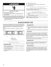
... in terminal box using UL listed wire connectors. 5. The fan will turn the fan ON. Light control B. Blower control C. When the heat decreases, the fan will turn range hood light OFF. Move the fan speed switch to do so can result in terminal box. Connect green (or bare) ground wire from your new range hood, read the "Range Hood Use" section. Install terminal box cover. 6. Reconnect power. Install Vent Covers (Optional) If you are located on the underside of the range hood blower and light. Operating the fan 1. When the fan switch is...
... in terminal box using UL listed wire connectors. 5. The fan will turn the fan ON. Light control B. Blower control C. When the heat decreases, the fan will turn range hood light OFF. Move the fan speed switch to do so can result in terminal box. Connect green (or bare) ground wire from your new range hood, read the "Range Hood Use" section. Install terminal box cover. 6. Reconnect power. Install Vent Covers (Optional) If you are located on the underside of the range hood blower and light. Operating the fan 1. When the fan switch is...

Installation Guide
Page 14
... of Whirlpool Corporation or Whirlpool Canada LP (hereafter "KitchenAid") will need to know your complete model number and serial number. Outside the 50 United States and Canada, this information on the model and serial number label located on how to repair or replace appliance light bulbs, air filters or water filters. Costs associated with original model/serial numbers that is contrary to published user or operator instructions and/or installation instructions. 4. Repairs to parts or systems resulting from unauthorized modifications...
... of Whirlpool Corporation or Whirlpool Canada LP (hereafter "KitchenAid") will need to know your complete model number and serial number. Outside the 50 United States and Canada, this information on the model and serial number label located on how to repair or replace appliance light bulbs, air filters or water filters. Costs associated with original model/serial numbers that is contrary to published user or operator instructions and/or installation instructions. 4. Repairs to parts or systems resulting from unauthorized modifications...
Warranty Information
Page 1
... removed, altered or cannot be repaired in the home and only in accordance with published installation instructions. 10. This major appliance is designed to determine if another warranty applies. KITCHENAID SHALL NOT BE LIABLE FOR INCIDENTAL OR CONSEQUENTIAL DAMAGES. If outside the 50 United States and Canada, contact your major appliance, to replace or repair house fuses, or to repair or replace appliance light bulbs, air filters or water filters...
... removed, altered or cannot be repaired in the home and only in accordance with published installation instructions. 10. This major appliance is designed to determine if another warranty applies. KITCHENAID SHALL NOT BE LIABLE FOR INCIDENTAL OR CONSEQUENTIAL DAMAGES. If outside the 50 United States and Canada, contact your major appliance, to replace or repair house fuses, or to repair or replace appliance light bulbs, air filters or water filters...


