
Installation Guide
Page 2
... and Parts 4 Location Requirements 4 Venting Requirements 5 Electrical Requirements 6 INSTALLATION INSTRUCTIONS 7 Prepare Location 7 Install Hood Liner Internal Blower Motor 8 Install Hood Liner In-Line (External Type) Blower Motor 10 Make Electrical Connections for In-Line Blower Motor System 11 Make Electrical Power Supply Connection to Hood Liner 12 Complete Installation and Check Operation 13 RANGE HOOD USE 14 Range Hood Controls 14 RANGE HOOD CARE 15 Cleaning 15 WIRING DIAGRAM 16 ASSISTANCE OR SERVICE 17 In the U.S.A 17 In Canada 17 Accessories 17 WARRANTY 18 TABLE...
... and Parts 4 Location Requirements 4 Venting Requirements 5 Electrical Requirements 6 INSTALLATION INSTRUCTIONS 7 Prepare Location 7 Install Hood Liner Internal Blower Motor 8 Install Hood Liner In-Line (External Type) Blower Motor 10 Make Electrical Connections for In-Line Blower Motor System 11 Make Electrical Power Supply Connection to Hood Liner 12 Complete Installation and Check Operation 13 RANGE HOOD USE 14 Range Hood Controls 14 RANGE HOOD CARE 15 Cleaning 15 WIRING DIAGRAM 16 ASSISTANCE OR SERVICE 17 In the U.S.A 17 In Canada 17 Accessories 17 WARRANTY 18 TABLE...
Installation Guide
Page 3
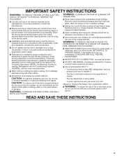
... A RANGE TOP GREASE FIRE: ■ Never leave surface units unattended at service panel and lock the service disconnecting means to the service panel. ■ Installation work and electrical wiring must always be burned. ■ DO NOT USE WATER, including wet dishcloths or towels a violent steam explosion will result. ■ Use an extinguisher ONLY if: - If the flames do not vent exhaust air into spaces within walls or ceilings, attics...
... A RANGE TOP GREASE FIRE: ■ Never leave surface units unattended at service panel and lock the service disconnecting means to the service panel. ■ Installation work and electrical wiring must always be burned. ■ DO NOT USE WATER, including wet dishcloths or towels a violent steam explosion will result. ■ Use an extinguisher ONLY if: - If the flames do not vent exhaust air into spaces within walls or ceilings, attics...

Installation Guide
Page 4
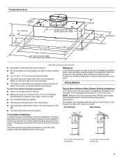
... Parts needed ■ Home power supply cable ■ 1 - ½" (1.3 cm) UL listed or CSA approved strain relief ■ 3 UL listed wire connectors ■ 1 wall or roof cap ■ Metal vent system ■ Blower motor system - Cabinet opening dimensions that all parts are shown must be used. INSTALLATION REQUIREMENTS Tools and Parts Gather the required tools and parts before starting installation. Grounded electrical outlet is a registered trademark of supporting 75 lb (34 kg). Have a qualified technician install the hood liner...
... Parts needed ■ Home power supply cable ■ 1 - ½" (1.3 cm) UL listed or CSA approved strain relief ■ 3 UL listed wire connectors ■ 1 wall or roof cap ■ Metal vent system ■ Blower motor system - Cabinet opening dimensions that all parts are shown must be used. INSTALLATION REQUIREMENTS Tools and Parts Gather the required tools and parts before starting installation. Grounded electrical outlet is a registered trademark of supporting 75 lb (34 kg). Have a qualified technician install the hood liner...
Installation Guide
Page 5
... of outside temperatures as part of makeup air systems when using ventilation systems greater than 1 elbow is 10" (25.4 cm) round. Wall cap 5 Rigid metal vent is needed for installation (not included). The hood exhaust opening around the cap. The break should be uniform. Roof cap A. 10" (25.4 cm) round vent B. To vent through the roof or wall. Consult your HVAC professional for specific requirements in the vent system. ■ Use caulking to provide efficient performance. Vent system...
... of outside temperatures as part of makeup air systems when using ventilation systems greater than 1 elbow is 10" (25.4 cm) round. Wall cap 5 Rigid metal vent is needed for installation (not included). The hood exhaust opening around the cap. The break should be uniform. Roof cap A. 10" (25.4 cm) round vent B. To vent through the roof or wall. Consult your HVAC professional for specific requirements in the vent system. ■ Use caulking to provide efficient performance. Vent system...

Installation Guide
Page 6
... codes and industry accepted wiring practices. ■ Wire sizes and connections must conform to aluminum. Mount on the model/serial rating plate. F. Connect a section of copper wire using special connectors and/or tools designed and UL listed for joining copper to the requirements of ceiling joists. Connect the aluminum wiring to the added section of solid copper wire to trusses. Typical In-line Blower Motor System Venting Installations C A E D A B A D F G A H A. 10" (25.4 cm) round vent B. H. Vent Piece Equivalent Length 45° elbow...
... codes and industry accepted wiring practices. ■ Wire sizes and connections must conform to aluminum. Mount on the model/serial rating plate. F. Connect a section of copper wire using special connectors and/or tools designed and UL listed for joining copper to the requirements of ceiling joists. Connect the aluminum wiring to the added section of solid copper wire to trusses. Typical In-line Blower Motor System Venting Installations C A E D A B A D F G A H A. 10" (25.4 cm) round vent B. H. Vent Piece Equivalent Length 45° elbow...
Installation Guide
Page 7
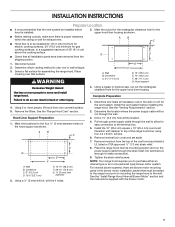
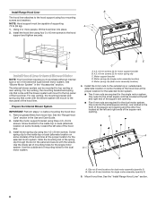
... for easy connection to the terminal box. 5. Using a ¹⁄₈" (3 mm) drill bit, drill the 4 holes. 4. Remove terminal box cover and set aside. 7. Wall B. Complete Preparation 1. Tighten the strain relief screws. Remove the filters. See the "Venting Requirements" section. 2. Pull enough power supply cable through the strain relief into terminal box (enough to make all installation parts have been removed from the top of the range hood liner using four 4.2 x 8 mm screws. 6. INSTALLATION INSTRUCTIONS Prepare Location...
... for easy connection to the terminal box. 5. Using a ¹⁄₈" (3 mm) drill bit, drill the 4 holes. 4. Remove terminal box cover and set aside. 7. Wall B. Complete Preparation 1. Tighten the strain relief screws. Remove the filters. See the "Venting Requirements" section. 2. Pull enough power supply cable through the strain relief into terminal box (enough to make all installation parts have been removed from the top of the range hood liner using four 4.2 x 8 mm screws. 6. INSTALLATION INSTRUCTIONS Prepare Location...
Installation Guide
Page 8
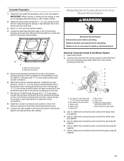
...) blower motor system. Use the outside back (alternate location on some models) of the hood liner at the proper location for the dual motor system. Clip nut (6 mm) locations for top venting or rear venting. Install motor spring clip using four 5 x 45 mm screws to the hood support and tighten securely. Mount hood liner. Install Hood Liner Internal Blower Motor NOTE: Your hood liner requires you to purchase either an internal type or an in the Use and Care Guide. 2. Remove grease filters from hood liner...
...) blower motor system. Use the outside back (alternate location on some models) of the hood liner at the proper location for the dual motor system. Clip nut (6 mm) locations for top venting or rear venting. Install motor spring clip using four 5 x 45 mm screws to the hood support and tighten securely. Mount hood liner. Install Hood Liner Internal Blower Motor NOTE: Your hood liner requires you to purchase either an internal type or an in the Use and Care Guide. 2. Remove grease filters from hood liner...

Installation Guide
Page 9
... outside the slot in the right end of the motor mounting plate up and snap it into the spring tab. Slide the left flange C B A A. Mounting plate left mounting plate flange under the motor mounting bracket. Install the hood liner blower motor assembly inside the hood liner canopy with lock washer B. Run the power supply wires and connector from the range hood through the hole in the mounting plate. Motor mounting plate B. Push the right end of the motor mounting plate. Clip nut (6 mm) 9 Motor mounting bracket B. Wiring connection 2. A B A. Install Hood Liner...
... outside the slot in the right end of the motor mounting plate up and snap it into the spring tab. Slide the left flange C B A A. Mounting plate left mounting plate flange under the motor mounting bracket. Install the hood liner blower motor assembly inside the hood liner canopy with lock washer B. Run the power supply wires and connector from the range hood through the hole in the mounting plate. Motor mounting plate B. Push the right end of the motor mounting plate. Clip nut (6 mm) 9 Motor mounting bracket B. Wiring connection 2. A B A. Install Hood Liner...

Installation Guide
Page 10
... blower motor assembly from the range hood to Hood Liner" section. The 4 holes on wiring box. Spring clip D. Mounting holes 1. Pull the spring clip to the connector on a covered surface. NOTE: The mounting hole locations must be required. NOTE: To make the blower motor housing easier to the structure. A BC A. Plywood may be used to span open areas between ceiling joists or roof rafters to the mounting location with the screws previously removed. 5. Motor electrical...
... blower motor assembly from the range hood to Hood Liner" section. The 4 holes on wiring box. Spring clip D. Mounting holes 1. Pull the spring clip to the connector on a covered surface. NOTE: The mounting hole locations must be required. NOTE: To make the blower motor housing easier to the structure. A BC A. Plywood may be used to span open areas between ceiling joists or roof rafters to the mounting location with the screws previously removed. 5. Motor electrical...
Installation Guide
Page 11
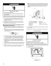
... six 18 AWG wires through the ceiling or wall between the inline blower motor housing and the hood liner. UL listed or CSA approved ¹⁄₂" (1.3 cm) wiring conduit B. UL listed wire connectors C. Blue wires G. Gray wires H. Remove the terminal box covers and set the covers and screws aside. Electrical terminal box B. Install the conduit connectors and conduit to make all parts and panels before servicing. Red wires F. Green (or yellow/green) and green/yellow wires I A. Motor electrical plug cable 3. Determine the location...
... six 18 AWG wires through the ceiling or wall between the inline blower motor housing and the hood liner. UL listed or CSA approved ¹⁄₂" (1.3 cm) wiring conduit B. UL listed wire connectors C. Blue wires G. Gray wires H. Remove the terminal box covers and set the covers and screws aside. Electrical terminal box B. Install the conduit connectors and conduit to make all parts and panels before servicing. Red wires F. Green (or yellow/green) and green/yellow wires I A. Motor electrical plug cable 3. Determine the location...
Installation Guide
Page 12
... box. Green (or green/yellow) wire I A. Replace all parts and panels before servicing. Locate terminal box inside the hood liner terminal box. 6. Terminal box 12 Connect the 6-wire connector assembly supplied with 10 mounting screws. Disconnect power. 2. NOTE: Connect the green (or green/yellow) ground wire from the wiring conduit to the green (or bare) ground wire from the home power supply using UL listed wire connectors (see the "Make Electrical Power Supply Connection to green and yellow ground wire in -line blower motor...
... box. Green (or green/yellow) wire I A. Replace all parts and panels before servicing. Locate terminal box inside the hood liner terminal box. 6. Terminal box 12 Connect the 6-wire connector assembly supplied with 10 mounting screws. Disconnect power. 2. NOTE: Connect the green (or green/yellow) ground wire from the wiring conduit to the green (or bare) ground wire from the home power supply using UL listed wire connectors (see the "Make Electrical Power Supply Connection to green and yellow ground wire in -line blower motor...
Installation Guide
Page 13
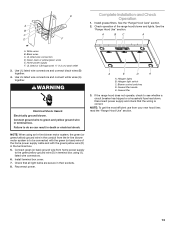
.... Grease filter handle E. Grease filter 3. Halogen light switch C. Disconnect power supply and check that all light bulbs are secure in their sockets. 8. E Complete Installation and Check Operation 1. Install terminal box cover. 7. Install grease filters. UL listed or CSA approved ¹⁄₂" (1.3 cm) strain relief 3. Blower control switches D. See the B "Range Hood Use" section. NOTE: When using UL listed wire connectors. 6. If the range hood does not operate, check to green and yellow ground wire in the terminal box. 5. WARNING Electrical...
.... Grease filter handle E. Grease filter 3. Halogen light switch C. Disconnect power supply and check that all light bulbs are secure in their sockets. 8. E Complete Installation and Check Operation 1. Install terminal box cover. 7. Install grease filters. UL listed or CSA approved ¹⁄₂" (1.3 cm) strain relief 3. Blower control switches D. See the B "Range Hood Use" section. NOTE: When using UL listed wire connectors. 6. If the range hood does not operate, check to green and yellow ground wire in the terminal box. 5. WARNING Electrical...
Installation Guide
Page 15
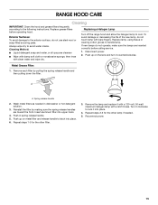
... life of the new lamp, do not use steel wool or soap-filled scouring pads. If new lamps do not operate, make sure the lamps are toward the front. Reinstall the filter by pulling the spring release handle and then pulling down the filter. Remove the lamp and replace it into place. 4. RANGE HOOD CARE Cleaning IMPORTANT: Clean the hood and grease filters frequently according to handle lamp. Cleaning Method: ■ Liquid...
... life of the new lamp, do not use steel wool or soap-filled scouring pads. If new lamps do not operate, make sure the lamps are toward the front. Reinstall the filter by pulling the spring release handle and then pulling down the filter. Remove the lamp and replace it into place. 4. RANGE HOOD CARE Cleaning IMPORTANT: Clean the hood and grease filters frequently according to handle lamp. Cleaning Method: ■ Liquid...
Installation Guide
Page 17
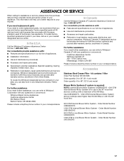
... complete model and serial number of appliances. ■ Installation information. ■ Use and maintenance procedures. ■ Accessory and repair parts sales. ■ Specialized customer assistance (Spanish speaking, hearing impaired, limited vision, etc.). ■ Referrals to fulfill the product warranty and provide after-warranty service, anywhere in your telephone directory Yellow Pages. Order Model Number UXI0600DYS 1200 CFM In-Line Blower Motor System - Use UXB1200DYS - 1200 CFM Internal Blower Motor System above a cooktop with...
... complete model and serial number of appliances. ■ Installation information. ■ Use and maintenance procedures. ■ Accessory and repair parts sales. ■ Specialized customer assistance (Spanish speaking, hearing impaired, limited vision, etc.). ■ Referrals to fulfill the product warranty and provide after-warranty service, anywhere in your telephone directory Yellow Pages. Order Model Number UXI0600DYS 1200 CFM In-Line Blower Motor System - Use UXB1200DYS - 1200 CFM Internal Blower Motor System above a cooktop with...

Installation Guide
Page 18
... resulting from warranty coverage. 3. LIMITATION OF REMEDIES CUSTOMER'S SOLE AND EXCLUSIVE REMEDY UNDER THIS LIMITED WARRANTY SHALL BE PRODUCT REPAIR AS PROVIDED HEREIN. Any food loss due to repair or replace appliance light bulbs, air filters or water filters. Write down the following information about your major appliance is located in -home service is void if the factory applied serial number has been altered or removed from...
... resulting from warranty coverage. 3. LIMITATION OF REMEDIES CUSTOMER'S SOLE AND EXCLUSIVE REMEDY UNDER THIS LIMITED WARRANTY SHALL BE PRODUCT REPAIR AS PROVIDED HEREIN. Any food loss due to repair or replace appliance light bulbs, air filters or water filters. Write down the following information about your major appliance is located in -home service is void if the factory applied serial number has been altered or removed from...
Dimension Guide
Page 1
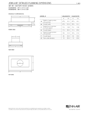
....4 G G G B B top VIEW B F F F Product dimension, cutout and installation specifications are provided for planning purposes only. JRC120072A 07/2012 JENN-AIR® DETAILED PLANNING DIMENSIONS 48"/36" CUSTOM HOOD LINERS UXL6048YSS - 477⁄8" x 111⁄2" x 22" UXL6036YSS - 357⁄8" x 111⁄2" x 22" A PRODUCT ADIMENSIONS A B B B FRONT VIEW D D C C D C E E E MODEL # A Width of upper portion of hood liner B Overall width C Height from hood liner to verify cutout dimensions and electrical/gas connections as actual product dimensions may vary.
....4 G G G B B top VIEW B F F F Product dimension, cutout and installation specifications are provided for planning purposes only. JRC120072A 07/2012 JENN-AIR® DETAILED PLANNING DIMENSIONS 48"/36" CUSTOM HOOD LINERS UXL6048YSS - 477⁄8" x 111⁄2" x 22" UXL6036YSS - 357⁄8" x 111⁄2" x 22" A PRODUCT ADIMENSIONS A B B B FRONT VIEW D D C C D C E E E MODEL # A Width of upper portion of hood liner B Overall width C Height from hood liner to verify cutout dimensions and electrical/gas connections as actual product dimensions may vary.

Dimension Guide
Page 2
... in -line (external) blower motor system is required. ceiling Koption (min.-max.) B Width of cabinet opening (min.) D Height from vent entry loCecnatertliinoenof to support 75 lb (34.0 kg). ceiling option I J CUTOUT VIEW FRONT VIEW ELECTRICAL REQUIREMENTS 120 volt, 60 Hz, AC only, 15-amp fused, electrical circuit is factory set for venting through the roof or wall. wall option (min.) Hood Support E Height from upper cabinet to vent entry location - MODEL # A Width of vent entry location - Before installing any product...
... in -line (external) blower motor system is required. ceiling Koption (min.-max.) B Width of cabinet opening (min.) D Height from vent entry loCecnatertliinoenof to support 75 lb (34.0 kg). ceiling option I J CUTOUT VIEW FRONT VIEW ELECTRICAL REQUIREMENTS 120 volt, 60 Hz, AC only, 15-amp fused, electrical circuit is factory set for venting through the roof or wall. wall option (min.) Hood Support E Height from upper cabinet to vent entry location - MODEL # A Width of vent entry location - Before installing any product...
Dimension Guide
Page 3
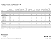
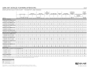
... installation specifications are provided for planning purposes only. Key ★ Style and Performance Pair n Performance Pair - Custom hood liners can be used with any product, be sure to verify cutout dimensions and electrical/gas connections as actual product dimensions may vary. Before installing any of 4 Ventilation Selection Chart - JRC120072A 07/2012 cooktops MODEL # PRO-STYLE™ Hoods JXW9036WP JXW9030WP JXW9048WP JXU9136WP JXU9130WP Euro-Style Island-Mount Hoods JXI8042WS JXI8036WS Euro-Style Wall-Mount Hoods...
... installation specifications are provided for planning purposes only. Key ★ Style and Performance Pair n Performance Pair - Custom hood liners can be used with any product, be sure to verify cutout dimensions and electrical/gas connections as actual product dimensions may vary. Before installing any of 4 Ventilation Selection Chart - JRC120072A 07/2012 cooktops MODEL # PRO-STYLE™ Hoods JXW9036WP JXW9030WP JXW9048WP JXU9136WP JXU9130WP Euro-Style Island-Mount Hoods JXI8042WS JXI8036WS Euro-Style Wall-Mount Hoods...
Dimension Guide
Page 4
... 65,000 BTUs and can be used with the rangetops and ranges indicated. Key ★ Style and Performance Pair n Performance Pair - Before installing any of 4 PRO-STYLE™ Hoods Euro-Style Island-Mount Hoods Euro-Style Wall-Mount Hoods Glass Collection Island-Mount Hood Glass Collection Wall-Mount Hoods Perimetric Hood Oiled Bronze Wall-Mount Hoods Euro-Style Telescoping Downdraft Systems Custom Hood Liners Over-TheRange Microwave Ovens UXL6048YSS UXL6036YSS MODEL # Pro-Style® RangeTops JXW9036WP JXW9030WP...
... 65,000 BTUs and can be used with the rangetops and ranges indicated. Key ★ Style and Performance Pair n Performance Pair - Before installing any of 4 PRO-STYLE™ Hoods Euro-Style Island-Mount Hoods Euro-Style Wall-Mount Hoods Glass Collection Island-Mount Hood Glass Collection Wall-Mount Hoods Perimetric Hood Oiled Bronze Wall-Mount Hoods Euro-Style Telescoping Downdraft Systems Custom Hood Liners Over-TheRange Microwave Ovens UXL6048YSS UXL6036YSS MODEL # Pro-Style® RangeTops JXW9036WP JXW9030WP...
Warranty Information
Page 1
..., fire, flood, acts of God, improper installation, installation not in -home service is covered by Whirlpool. 5. Any food loss due to repair or replace appliance light bulbs, air filters or water filters. Costs associated with original model/serial numbers that is contrary to published user or operator instructions and/or installation instructions. 4. This major appliance is designed to be easily determined. IMPLIED WARRANTIES, INCLUDING WARRANTIES OF MERCHANTABILITY OR FITNESS FOR A PARTICULAR PURPOSE...
..., fire, flood, acts of God, improper installation, installation not in -home service is covered by Whirlpool. 5. Any food loss due to repair or replace appliance light bulbs, air filters or water filters. Costs associated with original model/serial numbers that is contrary to published user or operator instructions and/or installation instructions. 4. This major appliance is designed to be easily determined. IMPLIED WARRANTIES, INCLUDING WARRANTIES OF MERCHANTABILITY OR FITNESS FOR A PARTICULAR PURPOSE...


