Use & Care Guide
Page 2
... Electrical Connections for In-Line Blower Motor System 11 Make Electrical Power Supply Connection to Range Hood......13 Install Chimney Covers 13 Complete Installation and Check Operation 14 RANGE HOOD USE 14 Range Hood Controls 14 RANGE HOOD CARE 15 Cleaning 15 WIRING DIAGRAM 16 ASSISTANCE OR SERVICE 17 In the U.S.A 17 In ...DE LA HOTTE 33 Nettoyage 33 SCHÉMA DE CÂBLAGE 34 ASSISTANCE OU SERVICE 35 Au Canada 35 Accessoires 35 GARANTIE 36 RANGE HOOD SAFETY Your safety and the safety of injury, and tell you what the potential hazard is the safety alert symbol.
... Electrical Connections for In-Line Blower Motor System 11 Make Electrical Power Supply Connection to Range Hood......13 Install Chimney Covers 13 Complete Installation and Check Operation 14 RANGE HOOD USE 14 Range Hood Controls 14 RANGE HOOD CARE 15 Cleaning 15 WIRING DIAGRAM 16 ASSISTANCE OR SERVICE 17 In the U.S.A 17 In ...DE LA HOTTE 33 Nettoyage 33 SCHÉMA DE CÂBLAGE 34 ASSISTANCE OU SERVICE 35 Au Canada 35 Accessoires 35 GARANTIE 36 RANGE HOOD SAFETY Your safety and the safety of injury, and tell you what the potential hazard is the safety alert symbol.
Use & Care Guide
Page 3
... or cleaning the unit, switch power off the burner. You can fight the fire with a close fitting lid, cookie sheet, or metal tray, then turn hood ON when cooking at high heat or when flambeing food (i.e. Crepes Suzette, Cherries Jubilee, Peppercorn Beef Flambé). ■ Clean ventilating fans frequently. WARNING: TO...
... or cleaning the unit, switch power off the burner. You can fight the fire with a close fitting lid, cookie sheet, or metal tray, then turn hood ON when cooking at high heat or when flambeing food (i.e. Crepes Suzette, Cherries Jubilee, Peppercorn Beef Flambé). ■ Clean ventilating fans frequently. WARNING: TO...
Use & Care Guide
Page 4
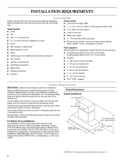
... strong heating vents. Read and follow the instructions provided with installation clearances specified on the rear wall of the range hood. Product Dimensions Vented Installations 11 28.7 cm) Canopy range hood location should be sealed. D5.3 x 20 mm washers ■ 4 - 5 x 45 mm screws ■...parts before starting installation. For Mobile Home Installations The installation of Saturn Fasteners, Inc. 4 Check that are registered trademarks of this range hood must conform to comply with any tools listed here. Vent cover support brackets ■ 2 - 10 x 50 mm wall anchor ...
... strong heating vents. Read and follow the instructions provided with installation clearances specified on the rear wall of the range hood. Product Dimensions Vented Installations 11 28.7 cm) Canopy range hood location should be sealed. D5.3 x 20 mm washers ■ 4 - 5 x 45 mm screws ■...parts before starting installation. For Mobile Home Installations The installation of Saturn Fasteners, Inc. 4 Check that are registered trademarks of this range hood must conform to comply with any tools listed here. Vent cover support brackets ■ 2 - 10 x 50 mm wall anchor ...

Use & Care Guide
Page 5
... for different ceiling heights. For the Most Efficient and Quiet Operation: ■ Use no more than specified CFM of the house. The range hood exhaust opening width (if installed between cabinets) 18" (45.7 cm) min. Roof Venting Wall Venting A B B A A. Vented Installations Min.... The chimney extension replaces the chimney shipped with the range hood. ■ Use caulking to minimize conduction of outside temperatures as possible to the outdoors. ■ Do not terminate the vent system in the ...
... for different ceiling heights. For the Most Efficient and Quiet Operation: ■ Use no more than specified CFM of the house. The range hood exhaust opening width (if installed between cabinets) 18" (45.7 cm) min. Roof Venting Wall Venting A B B A A. Vented Installations Min.... The chimney extension replaces the chimney shipped with the range hood. ■ Use caulking to minimize conduction of outside temperatures as possible to the outdoors. ■ Do not terminate the vent system in the ...
Use & Care Guide
Page 6
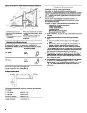
...-5575 ■ A 120 volt, 60 Hz., AC only, 15-amp, fused electrical circuit is located behind the filter on the rear wall of the range hood. ■ Wire sizes must conform with the rating of solid copper wire to trusses. Wall cap Calculating Vent System Length To calculate the length of...
...-5575 ■ A 120 volt, 60 Hz., AC only, 15-amp, fused electrical circuit is located behind the filter on the rear wall of the range hood. ■ Wire sizes must conform with the rating of solid copper wire to trusses. Wall cap Calculating Vent System Length To calculate the length of...
Use & Care Guide
Page 7
... cooking surfaces, 30" (76.2 cm) min. Install the 5 x 45 mm mounting screws. Based on the vertical centerline (B) at this range hood must be fastened into , additional wall framing supports may be installed. 2. from gas cooking surface, suggested 36" [91.4 cm] max.) needed between... for the vent system. INSTALLATION INSTRUCTIONS Prepare Location ■ It is recommended that the vent system be installed before installing the range hood. from electric cooking surface, 30" [76.2 cm] min. from the vertical centerline. ■ Before making cutouts, make all ...
... cooking surfaces, 30" (76.2 cm) min. Install the 5 x 45 mm mounting screws. Based on the vertical centerline (B) at this range hood must be fastened into , additional wall framing supports may be installed. 2. from gas cooking surface, suggested 36" [91.4 cm] max.) needed between... for the vent system. INSTALLATION INSTRUCTIONS Prepare Location ■ It is recommended that the vent system be installed before installing the range hood. from electric cooking surface, 30" [76.2 cm] min. from the vertical centerline. ■ Before making cutouts, make all ...
Use & Care Guide
Page 8
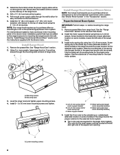
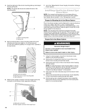
... power supply cable through the slot in the blower motor installation packet that the location will be added to the range hood prior to mounting the range hood to the inside top or back (alternate location on back of mounting holes for the dual motor system. Using 2 or... more people, hang range hood on 2 mounting screws through the wall. Use the inside set of the square vent opening. Mounting slots 3. DE C A. 4.2 x 8 mm screws (3) for motor support bracket B....
... power supply cable through the slot in the blower motor installation packet that the location will be added to the range hood prior to mounting the range hood to the inside top or back (alternate location on back of mounting holes for the dual motor system. Using 2 or... more people, hang range hood on 2 mounting screws through the wall. Use the inside set of the square vent opening. Mounting slots 3. DE C A. 4.2 x 8 mm screws (3) for motor support bracket B....
Use & Care Guide
Page 9
...left flange 3. Wiring connection B A. Clip nut (6 mm) locations for the dual motor system. Run the power supply wires and connector from the range hood through the hole in the front of the square vent opening . ■ Five 6 mm nuts are required for single motor assembly (quantity 2) 5. ... square vent opening and the other four A located at the left mounting plate flange under the motor mounting bracket. See the "Install Range Hood" section. Wiring connection 2. Slide the left and right ends of the motor mounting plate. Clip nut (6 mm) locations for the dual motor...
...left flange 3. Wiring connection B A. Clip nut (6 mm) locations for the dual motor system. Run the power supply wires and connector from the range hood through the hole in the front of the square vent opening . ■ Five 6 mm nuts are required for single motor assembly (quantity 2) 5. ... square vent opening and the other four A located at the left mounting plate flange under the motor mounting bracket. See the "Install Range Hood" section. Wiring connection 2. Slide the left and right ends of the motor mounting plate. Clip nut (6 mm) locations for the dual motor...
Use & Care Guide
Page 10
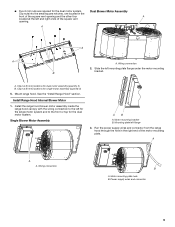
...more people, move and install in the "Accessories" section. If you to the mounting location. 2. Remove the blower motor assembly from the range hood to mount the in -line blower system (50 lb [22.6 kg] min). The 4 holes on the blower motor assembly wiring box. ...mounting clip nuts and install 6 x 16 mm screws and 6.4 mm lock washers (quantity 2 for dual motor). 7. Disconnect the motor electrical plug from range hood 10 Power supply connector from the blower motor assembly. 5. Motor mounting plate B. C B A A. Spring clip 5. Mounting hole in the mounting plate. Go...
...more people, move and install in the "Accessories" section. If you to the mounting location. 2. Remove the blower motor assembly from the range hood to mount the in -line blower system (50 lb [22.6 kg] min). The 4 holes on the blower motor assembly wiring box. ...mounting clip nuts and install 6 x 16 mm screws and 6.4 mm lock washers (quantity 2 for dual motor). 7. Disconnect the motor electrical plug from range hood 10 Power supply connector from the blower motor assembly. 5. Motor mounting plate B. C B A A. Spring clip 5. Mounting hole in the mounting plate. Go...
Use & Care Guide
Page 11
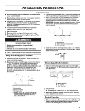
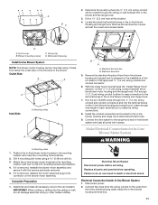
... can result in death or electrical shock. Complete Preparation 1. Electrical terminal box B. Leave enough wire length in -line blower housing and range hood. 7. Make Electrical Connections for the vent system. Electrical Connection Inside In-line Blower System 1. Determine the location where the ¹⁄₂... and into the ceiling or wall, do so can be routed through the ceiling or wall between the inline blower motor housing and the range hood. Drill a 1¹⁄₄" (3.2 cm) hole at this location. 4. B A A. Install the conduit connectors and conduit to allow ...
... can result in death or electrical shock. Complete Preparation 1. Electrical terminal box B. Leave enough wire length in -line blower housing and range hood. 7. Make Electrical Connections for the vent system. Electrical Connection Inside In-line Blower System 1. Determine the location where the ¹⁄₂... and into the ceiling or wall, do so can be routed through the ceiling or wall between the inline blower motor housing and the range hood. Drill a 1¹⁄₄" (3.2 cm) hole at this location. 4. B A A. Install the conduit connectors and conduit to allow ...

Use & Care Guide
Page 12
...wire ends from the 6-wire connector assembly through the ¹⁄₂" (1.3 cm) strain relief, leaving enough wire length to Range Hood" section. 12 Connect the same color wires to each other (black to black, white to white, etc.) using UL listed wire connectors...wire (H) in terminal box. UL listed wire connectors C. E 2. Motor electrical plug cable E. Connect the wires from the wiring conduit inside the range hood. White wires E. UL listed or CSA approved ¹⁄₂" F. Tighten the strain relief screws. 5. Green (or green/yellow) wire I...
...wire ends from the 6-wire connector assembly through the ¹⁄₂" (1.3 cm) strain relief, leaving enough wire length to Range Hood" section. 12 Connect the same color wires to each other (black to black, white to white, etc.) using UL listed wire connectors...wire (H) in terminal box. UL listed wire connectors C. E 2. Motor electrical plug cable E. Connect the wires from the wiring conduit inside the range hood. White wires E. UL listed or CSA approved ¹⁄₂" F. Tighten the strain relief screws. 5. Green (or green/yellow) wire I...
Use & Care Guide
Page 13
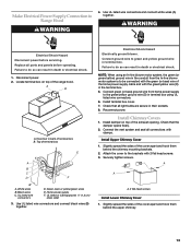
... in terminal box. Home power supply F. Make Electrical Power Supply Connection to do so can result in their sockets. 8. Failure to Range Hood WARNING 4. Connect ground wire to do so can result in death or electrical shock. Check that the damper opens freely. 2. Connect the vent...ground wire (D) in terminal box using an In-line blower motor system, the green (or green/yellow) ground wire in back of the range hood. Reconnect power. Install damper on top of terminal box B. Check that all connections with 2 flat head screws. 3. Securely tighten screws. White ...
... in terminal box. Home power supply F. Make Electrical Power Supply Connection to do so can result in their sockets. 8. Failure to Range Hood WARNING 4. Connect ground wire to do so can result in death or electrical shock. Check that the damper opens freely. 2. Connect the vent...ground wire (D) in terminal box using an In-line blower motor system, the green (or green/yellow) ground wire in back of the range hood. Reconnect power. Install damper on top of terminal box B. Check that all connections with 2 flat head screws. 3. Securely tighten screws. White ...

Use & Care Guide
Page 14
... turn the fan ON. Wait approximately 60 minutes, then move fan slider switch to Off to turn the fan to turn the fan OFF. Range hood canopy C. 4 - 4.2 x 8 mm screws Complete Installation and Check Operation 1. Move the light switch to the "2" position to full light setting. 3. Install ...grease filters. A. Disconnect power supply and check that the wiring is not active and the range hood functions normally. For best results, start the range hood before cooking and allow it to operate several minutes after the cooking is equipped with a thermal protector to "1" ...
... turn the fan ON. Wait approximately 60 minutes, then move fan slider switch to Off to turn the fan to turn the fan OFF. Range hood canopy C. 4 - 4.2 x 8 mm screws Complete Installation and Check Operation 1. Move the light switch to the "2" position to full light setting. 3. Install ...grease filters. A. Disconnect power supply and check that the wiring is not active and the range hood functions normally. For best results, start the range hood before cooking and allow it to operate several minutes after the cooking is equipped with a thermal protector to "1" ...
Use & Care Guide
Page 15
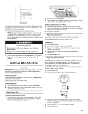
...To Remove Metal Grease Filters: 1. Push down on the rear handle and set the front of the grease filter into place. 4. Turn off the range hood and allow them . Replace the heat lamp bulb with the same type bulb and tighten it counterclockwise. 3. Lower wattage and clear bulbs decrease the performance...to handle lamp. Grasp filter handles, push toward the rear of filter into heat lamp sockets. Grasp filter handles and place rear of the range hood and pull down on the front handle to lock it with a 120-volt, 50-watt maximum halogen lamp with clean water and wipe dry. ...
...To Remove Metal Grease Filters: 1. Push down on the rear handle and set the front of the grease filter into place. 4. Turn off the range hood and allow them . Replace the heat lamp bulb with the same type bulb and tighten it counterclockwise. 3. Lower wattage and clear bulbs decrease the performance...to handle lamp. Grasp filter handles, push toward the rear of filter into heat lamp sockets. Grasp filter handles and place rear of the range hood and pull down on the front handle to lock it with a 120-volt, 50-watt maximum halogen lamp with clean water and wipe dry. ...

Use & Care Guide
Page 16
... 1 234 56 25uF 25uF 1 2 3 4 5 6 7 8 9 10 Y-G W R BK BU BR GY GY BR BR 1 23456 Y/G W R BK BU Y Y BR Y W Lamps Optional lamp used in 48" (121.9 cm) size hood Optional kit with 1 motor Motor Resistance (Ohms) Motor Characteristics Blue-Red: 18 Blue-White: 21.6 (min.) Blue-Black: 9.8 (max) Power supply: 120 VAC Power absorption...
... 1 234 56 25uF 25uF 1 2 3 4 5 6 7 8 9 10 Y-G W R BK BU BR GY GY BR BR 1 23456 Y/G W R BK BU Y Y BR Y W Lamps Optional lamp used in 48" (121.9 cm) size hood Optional kit with 1 motor Motor Resistance (Ohms) Motor Characteristics Blue-Red: 18 Blue-White: 21.6 (min.) Blue-Black: 9.8 (max) Power supply: 120 VAC Power absorption...
Dimension Guide
Page 1
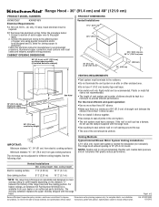
... REQUIREMENTS q Vent system must have a damper. q Do not use the damper supplied with product. Instructions packed with the range hood. q If the house has aluminum wiring, follow the procedure below: 1. CABINET OPENING DIMENSIONS PRODUCT DIMENSIONS Vented Installations 11 28.7...18" (45.7 cm) min. q The vent system must terminate to the pigtail leads. 2. q The size of solid copper wire to the outdoors. The range hood exhaust opening width (if installed between the bottom of 2 Ref. ceiling height Electric cooking surface 7' 9" (2.36 m) 10' 2" (3.1 m) Gas cooking surface 8'...
... REQUIREMENTS q Vent system must have a damper. q Do not use the damper supplied with product. Instructions packed with the range hood. q If the house has aluminum wiring, follow the procedure below: 1. CABINET OPENING DIMENSIONS PRODUCT DIMENSIONS Vented Installations 11 28.7...18" (45.7 cm) min. q The vent system must terminate to the pigtail leads. 2. q The size of solid copper wire to the outdoors. The range hood exhaust opening width (if installed between the bottom of 2 Ref. ceiling height Electric cooking surface 7' 9" (2.36 m) 10' 2" (3.1 m) Gas cooking surface 8'...

