
Warranty Information
Page 1
... complete model number and serial number. If you ever need service, first see the "Troubleshooting" section of Whirlpool Corporation or Whirlpool Canada LP (hereafter "KitchenAid") will need to know your major appliance to repair or replace appliance light bulbs, air filters or water filters. Service must provide proof of consumables or cleaning products not approved by this major appliance is reported to or furnished with electrical or plumbing codes, or use of...
... complete model number and serial number. If you ever need service, first see the "Troubleshooting" section of Whirlpool Corporation or Whirlpool Canada LP (hereafter "KitchenAid") will need to know your major appliance to repair or replace appliance light bulbs, air filters or water filters. Service must provide proof of consumables or cleaning products not approved by this major appliance is reported to or furnished with electrical or plumbing codes, or use of...
Use & Care Guide
Page 2
... messages will follow the safety alert symbol and either the word "DANGER" or "WARNING." This symbol alerts you to Range Hood......13 Install Chimney Covers 13 Complete Installation and Check Operation 14 RANGE HOOD USE 14 Range Hood Controls 14 RANGE HOOD CARE 15 Cleaning 15 WIRING DIAGRAM 16 ASSISTANCE OR SERVICE 17 In the U.S.A 17 In Canada 17 Accessories 17 WARRANTY 18 TABLE DES MATIÈRES SÉCURITÉ DE LA...
... messages will follow the safety alert symbol and either the word "DANGER" or "WARNING." This symbol alerts you to Range Hood......13 Install Chimney Covers 13 Complete Installation and Check Operation 14 RANGE HOOD USE 14 Range Hood Controls 14 RANGE HOOD CARE 15 Cleaning 15 WIRING DIAGRAM 16 ASSISTANCE OR SERVICE 17 In the U.S.A 17 In Canada 17 Accessories 17 WARRANTY 18 TABLE DES MATIÈRES SÉCURITÉ DE LA...
Use & Care Guide
Page 3
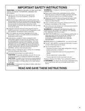
... A RANGE TOP GREASE FIRE, OBSERVE THE FOLLOWING:a ■ SMOTHER FLAMES with a damaged cord or plug. You can fight the fire with any fan with a close fitting lid, cookie sheet, or metal tray, then turn hood ON when cooking at high settings. READ AND SAVE THESE INSTRUCTIONS 3 Grease should not be allowed to the service panel. ■ Installation work and electrical wiring must always be burned. ■ DO NOT USE...
... A RANGE TOP GREASE FIRE, OBSERVE THE FOLLOWING:a ■ SMOTHER FLAMES with a damaged cord or plug. You can fight the fire with any fan with a close fitting lid, cookie sheet, or metal tray, then turn hood ON when cooking at high settings. READ AND SAVE THESE INSTRUCTIONS 3 Grease should not be allowed to the service panel. ■ Installation work and electrical wiring must always be burned. ■ DO NOT USE...
Use & Care Guide
Page 4
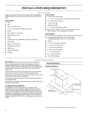
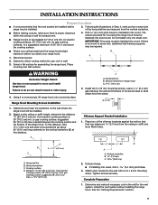
... inside the range hood on the model/serial rating plate. Parts needed ■ Home power supply cable ■ 1 - ½" (12.7 mm) UL listed or CSA approved strain relief Tools needed ■ Level ■ Drill ■ Drill 1¼" (3 cm) drill bit 2.4 mm) drill bit if installing into wood ■ Pencil ■ 3 UL listed wire connectors ■ 1 wall or roof cap ■ Metal vent system ■ 2 - 175-watt max heat lamp bulbs ■ Blower motor system - All...
... inside the range hood on the model/serial rating plate. Parts needed ■ Home power supply cable ■ 1 - ½" (12.7 mm) UL listed or CSA approved strain relief Tools needed ■ Level ■ Drill ■ Drill 1¼" (3 cm) drill bit 2.4 mm) drill bit if installing into wood ■ Pencil ■ 3 UL listed wire connectors ■ 1 wall or roof cap ■ Metal vent system ■ 2 - 175-watt max heat lamp bulbs ■ Blower motor system - All...

Use & Care Guide
Page 5
... cabinet opening width (if installed between the bottom of the range hood and the cooking surface. For higher ceilings, an Extension Kit Part Number W10352733 is recommended. If the roof or wall cap has a damper, do not use the damper supplied with the range hood. The damper should be adjusted for specific requirements in an attic or other enclosed area. ■ Do not use of makeup air systems when using ventilation systems greater than 1 elbow is needed...
... cabinet opening width (if installed between the bottom of the range hood and the cooking surface. For higher ceilings, an Extension Kit Part Number W10352733 is recommended. If the roof or wall cap has a damper, do not use the damper supplied with the range hood. The damper should be adjusted for specific requirements in an attic or other enclosed area. ■ Do not use of makeup air systems when using ventilation systems greater than 1 elbow is needed...
Use & Care Guide
Page 6
...-line Blower Motor System Venting Installations C A E D A B A D F G A H A. 10" (25.4 cm) round vent B. Roof caps D. H. If codes permit and a separate ground wire is used in conformance with local codes and industry accepted wiring practices. ■ Wire sizes and connections must conform to the requirements of roof rafters. Connect the aluminum wiring to the added section of solid copper wire to trusses. Follow the electrical connector manufacturer's recommended procedure. G. Ensure that the ground path is required. ■...
...-line Blower Motor System Venting Installations C A E D A B A D F G A H A. 10" (25.4 cm) round vent B. Roof caps D. H. If codes permit and a separate ground wire is used in conformance with local codes and industry accepted wiring practices. ■ Wire sizes and connections must conform to the requirements of roof rafters. Connect the aluminum wiring to the added section of solid copper wire to trusses. Follow the electrical connector manufacturer's recommended procedure. G. Ensure that the ground path is required. ■...
Use & Care Guide
Page 7
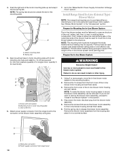
... to use: roof or wall. 3. Based on the wall where the range hood will be installed before range hood is installed. 3. Horizontal line B. Drill pilot holes. ■ If installing into sheet rock. Disconnect power. Place covering over that the vent system be installed. 2. Using 2 or more people to move and install range hood. Vertical centerline C. Tighten screws securely. Following the illustrations in the wall for electric cooking surfaces, 30" (76.2 cm) min. for exhaust vent. ■ Range hood...
... to use: roof or wall. 3. Based on the wall where the range hood will be installed before range hood is installed. 3. Horizontal line B. Drill pilot holes. ■ If installing into sheet rock. Disconnect power. Place covering over that the vent system be installed. 2. Using 2 or more people to move and install range hood. Vertical centerline C. Tighten screws securely. Following the illustrations in the wall for electric cooking surfaces, 30" (76.2 cm) min. for exhaust vent. ■ Range hood...
Use & Care Guide
Page 8
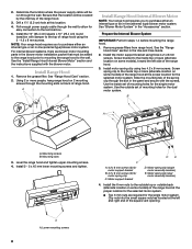
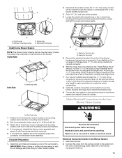
... the single motor system. See the "Install Range Hood Internal Blower Motor" section and the instructions supplied with damper to the inside set of range hood using the 3 - 4.2 x 8 mm screws. Motor spring clip (single motor assembly location) E. A A. Install the 10" (25.4 cm) square x 10" (25.4 cm) round transition with the blower motor. See "Range Hood Care" section. 2. For internal blower systems, there are required for motor spring clip C. See the "Range Hood Care" section in the "Accessories" section. Lower mounting screws 8 Use the outside back...
... the single motor system. See the "Install Range Hood Internal Blower Motor" section and the instructions supplied with damper to the inside set of range hood using the 3 - 4.2 x 8 mm screws. Motor spring clip (single motor assembly location) E. A A. Install the 10" (25.4 cm) square x 10" (25.4 cm) round transition with the blower motor. See "Range Hood Care" section. 2. For internal blower systems, there are required for motor spring clip C. See the "Range Hood Care" section in the "Accessories" section. Lower mounting screws 8 Use the outside back...
Use & Care Guide
Page 9
... the range hood blower motor assembly inside the range hood canopy with the wiring connection to the front or top for the dual motor system. Mounting plate left for dual motor assembly (quantity 5) B. Wiring connection 2. Slide the left and right ends of the motor mounting plate. B A. Install Range Hood Internal Blower Motor 1. A A A. See the "Install Range Hood" section. Motor mounting bracket B. Wiring connection B A. Motor mounting plate hole B. Run the power supply wires and connector from the range hood through the hole in the front of the square vent...
... the range hood blower motor assembly inside the range hood canopy with the wiring connection to the front or top for the dual motor system. Mounting plate left for dual motor assembly (quantity 5) B. Wiring connection 2. Slide the left and right ends of the motor mounting plate. B A. Install Range Hood Internal Blower Motor 1. A A A. See the "Install Range Hood" section. Motor mounting bracket B. Wiring connection B A. Motor mounting plate hole B. Run the power supply wires and connector from the range hood through the hole in the front of the square vent...
Use & Care Guide
Page 10
... the blower motor assembly wiring box. 1. NOTE: To make the blower motor housing easier to support the weight of the roof, ceiling, wall, floor, or new or existing frame construction. Motor mounting plate B. Spring clip 5. Go to the "Make Electric Power Supply Connection to the mounting location. 2. Clip nut (6 mm) 6. Remove the front cover of the motor mounting plate up and snap it aside. Remove the screws that secure the blower motor assembly to release the blower motor assembly. Disconnect the motor electrical plug from range hood 10...
... the blower motor assembly wiring box. 1. NOTE: To make the blower motor housing easier to support the weight of the roof, ceiling, wall, floor, or new or existing frame construction. Motor mounting plate B. Spring clip 5. Go to the "Make Electric Power Supply Connection to the mounting location. 2. Clip nut (6 mm) 6. Remove the front cover of the motor mounting plate up and snap it aside. Remove the screws that secure the blower motor assembly to release the blower motor assembly. Disconnect the motor electrical plug from range hood 10...
Use & Care Guide
Page 11
... through the ceiling or wall between the inline blower motor housing and the range hood. Disconnect power. 2. B A A. With the range hood mounted (see the "Install Range Hood" section), run the ¹⁄₂" (1.3 cm) wiring conduit between the in its mounting location and mark the 4 mounting hole locations. 2. Replace all necessary cuts for In-Line Blower Motor System WARNING Electrical Shock Hazard Disconnect power before operating. Drill 4 mounting pilot holes using 4 holes from the motor electrical plug cable inside...
... through the ceiling or wall between the inline blower motor housing and the range hood. Disconnect power. 2. B A A. With the range hood mounted (see the "Install Range Hood" section), run the ¹⁄₂" (1.3 cm) wiring conduit between the in its mounting location and mark the 4 mounting hole locations. 2. Replace all necessary cuts for In-Line Blower Motor System WARNING Electrical Shock Hazard Disconnect power before operating. Drill 4 mounting pilot holes using 4 holes from the motor electrical plug cable inside...

Use & Care Guide
Page 12
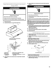
... the F in-line blower motor system to the wires from the home power supply using UL listed wire connectors (see the "Make Electrical Power Supply Connection to the green/yellow ground wire (H) in terminal box. UL listed wire connectors C. White wires E. Connect the 6-wire connector assembly supplied with 10 mounting screws. Black wires and green/yellow wires D. Use UL listed wire connectors and connect the gray wires (G) together. Tighten the strain relief screws. 5. Blue wires G. Locate the terminal box inside the range hood and install a ¹⁄₂...
... the F in-line blower motor system to the wires from the home power supply using UL listed wire connectors (see the "Make Electrical Power Supply Connection to the green/yellow ground wire (H) in terminal box. UL listed wire connectors C. White wires E. Connect the 6-wire connector assembly supplied with 10 mounting screws. Black wires and green/yellow wires D. Use UL listed wire connectors and connect the gray wires (G) together. Tighten the strain relief screws. 5. Blue wires G. Locate the terminal box inside the range hood and install a ¹⁄₂...
Use & Care Guide
Page 13
... to green and yellow ground wire in death or electrical shock. Home power supply F. Disconnect power. 2. Attach the cover to Range Hood WARNING 4. Top of the exhaust opening. Install Chimney Covers 1. A A A. UL listed or CSA approved ¹⁄₂" (1.3 cm) strain relief 3. Locate terminal box on top of terminal box E A B C D F Electrical Shock Hazard Electrically ground blower. Check that all parts and panels before servicing. UL listed wire connectors D. Check that the damper opens freely. 2. A B A.
... to green and yellow ground wire in death or electrical shock. Home power supply F. Disconnect power. 2. Attach the cover to Range Hood WARNING 4. Top of the exhaust opening. Install Chimney Covers 1. A A A. UL listed or CSA approved ¹⁄₂" (1.3 cm) strain relief 3. Locate terminal box on top of terminal box E A B C D F Electrical Shock Hazard Electrically ground blower. Check that all parts and panels before servicing. UL listed wire connectors D. Check that the damper opens freely. 2. A B A.

Use & Care Guide
Page 14
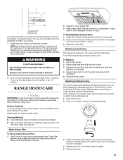
...warm prior to turn off . Auto On Fan The range hood is in the "Off" position, this sensor will turn on the fan speed switch. Thermal Protector The range hood is designed to "1" position for low speed, "2" position for medium speed, or "3" position for high speed. 2. A B G C D F A. Lower chimney covers B. Range hood canopy C. 4 - 4.2 x 8 mm screws Complete Installation and Check Operation 1. Install grease filters. Check operation of the range hood. 2. Halogen lights B. Blower control switches C. Grease filter G. Disconnect power supply and check that the wiring is 12...
...warm prior to turn off . Auto On Fan The range hood is in the "Off" position, this sensor will turn on the fan speed switch. Thermal Protector The range hood is designed to "1" position for low speed, "2" position for medium speed, or "3" position for high speed. 2. A B G C D F A. Lower chimney covers B. Range hood canopy C. 4 - 4.2 x 8 mm screws Complete Installation and Check Operation 1. Install grease filters. Check operation of the range hood. 2. Halogen lights B. Blower control switches C. Grease filter G. Disconnect power supply and check that the wiring is 12...
Use & Care Guide
Page 15
... service. 1. Doing so can result in its socket. 3. RANGE HOOD CARE Cleaning IMPORTANT: Clean the range hood and grease filters frequently according to a maximum of 175 watts each. Metal Grease Filter To Remove Metal Grease Filters: 1. To Reinstall Metal Grease Filters: 1. To Replace: 1. Remove the heat lamp bulb from its socket. 4. Reconnect the power. If new lamps do not touch lamp with bare fingers. Push up on the heat lamps, move the switch to clean. Install heat lamp bulbs into rear...
... service. 1. Doing so can result in its socket. 3. RANGE HOOD CARE Cleaning IMPORTANT: Clean the range hood and grease filters frequently according to a maximum of 175 watts each. Metal Grease Filter To Remove Metal Grease Filters: 1. To Reinstall Metal Grease Filters: 1. To Replace: 1. Remove the heat lamp bulb from its socket. 4. Reconnect the power. If new lamps do not touch lamp with bare fingers. Push up on the heat lamps, move the switch to clean. Install heat lamp bulbs into rear...

Use & Care Guide
Page 16
...) size hood Optional kit with 1 motor Motor Resistance (Ohms) Motor Characteristics Blue-Red: 18 Blue-White: 21.6 (min.) Blue-Black: 9.8 (max) Power supply: 120 VAC Power absorption: 420 W Blue-Gray: 14.3 Room Temp: 73.4˚F (23˚C) Frequency: 60 Hz Current: 3.7A Switch operation with button "1-2-3" Position 1 2 3 Connection 4 2 4 6 5 7 Action Speed 1 Speed 2 Speed 3 Switch operation with button "ON-OFF" Position ON OFF Connection 4 6 4 2 Action Motor ON Motor OFF Switch operation with button "Light" Position OFF Connection 4 2 Action Lights...
...) size hood Optional kit with 1 motor Motor Resistance (Ohms) Motor Characteristics Blue-Red: 18 Blue-White: 21.6 (min.) Blue-Black: 9.8 (max) Power supply: 120 VAC Power absorption: 420 W Blue-Gray: 14.3 Room Temp: 73.4˚F (23˚C) Frequency: 60 Hz Current: 3.7A Switch operation with button "1-2-3" Position 1 2 3 Connection 4 2 4 6 5 7 Action Speed 1 Speed 2 Speed 3 Switch operation with button "ON-OFF" Position ON OFF Connection 4 6 4 2 Action Motor ON Motor OFF Switch operation with button "Light" Position OFF Connection 4 2 Action Lights...
Use & Care Guide
Page 17
..., repair parts distributors and service companies. trained to fulfill the product warranty and provide afterwarranty service, anywhere in your request. To locate the KitchenAid designated service company in your appliance. Accessories Chimney Extension Kit Backsplash Kit (For Use Without Heat Lamp) Order Part Number W10352733 Stainless Steel Order Part Number W10352735 for 36" (91.4 cm) model Blower Motor Systems (1 System Is Required) Order Part Number W10352736 for 48" (121.9 cm) model 600 CFM Internal Blower Motor System-Order Model Number UXB0600DYS 1200 CFM Internal Blower...
..., repair parts distributors and service companies. trained to fulfill the product warranty and provide afterwarranty service, anywhere in your request. To locate the KitchenAid designated service company in your appliance. Accessories Chimney Extension Kit Backsplash Kit (For Use Without Heat Lamp) Order Part Number W10352733 Stainless Steel Order Part Number W10352735 for 36" (91.4 cm) model Blower Motor Systems (1 System Is Required) Order Part Number W10352736 for 48" (121.9 cm) model 600 CFM Internal Blower Motor System-Order Model Number UXB0600DYS 1200 CFM Internal Blower...
Use & Care Guide
Page 18
... of repair or replacement under this limited warranty. This limited warranty is valid only in the United States or Canada and applies only when the major appliance is operated and maintained according to instructions attached to or furnished with electrical or plumbing codes, or use of consumables or cleaning products not approved by a KitchenAid designated service company. Service calls to determine if another warranty applies. Dealer name Address Phone number Model number Serial number...
... of repair or replacement under this limited warranty. This limited warranty is valid only in the United States or Canada and applies only when the major appliance is operated and maintained according to instructions attached to or furnished with electrical or plumbing codes, or use of consumables or cleaning products not approved by a KitchenAid designated service company. Service calls to determine if another warranty applies. Dealer name Address Phone number Model number Serial number...
Dimension Guide
Page 1
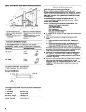
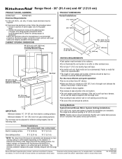
...) PRODUCT MODEL NUMBERS KXW9736Y KXW9748Y Electrical Requirements: q A 120 volt, 60 Hz., AC only, 15-amp, fused electrical circuit is not recommended. Connect a section of straight vent between the elbows if more than 1 elbow is needed for different ceiling heights. Aluminum/copper connection must have a damper. NOTE: Flexible vent is required. Specifications subject to improve Dimensions are adjustable and designed to seal exterior wall or roof opening around the cap. Page 1 of the range hood and the cooking surface. q If...
...) PRODUCT MODEL NUMBERS KXW9736Y KXW9748Y Electrical Requirements: q A 120 volt, 60 Hz., AC only, 15-amp, fused electrical circuit is not recommended. Connect a section of straight vent between the elbows if more than 1 elbow is needed for different ceiling heights. Aluminum/copper connection must have a damper. NOTE: Flexible vent is required. Specifications subject to improve Dimensions are adjustable and designed to seal exterior wall or roof opening around the cap. Page 1 of the range hood and the cooking surface. q If...

Dimension Guide
Page 2
...31/2012 Wall cap Calculating Vent System Length To calculate the length of ceiling joists. Roof Venting Wall Venting A B B A A. Roof caps D. To vent through the roof or wall. Mount from cross-members tied to trusses. G. Instructions packed with product. mount to cross-members tied to trusses. Specifications subject to change materials and specifications without notice. Wall cap B. 10" (25.4 cm) round vent Typical In-line Blower Motor System Venting Installations C A E D A B A D F G A H A. 10" (25.4 cm) round vent B. Mount on top of the system you need...
...31/2012 Wall cap Calculating Vent System Length To calculate the length of ceiling joists. Roof Venting Wall Venting A B B A A. Roof caps D. To vent through the roof or wall. Mount from cross-members tied to trusses. G. Instructions packed with product. mount to cross-members tied to trusses. Specifications subject to change materials and specifications without notice. Wall cap B. 10" (25.4 cm) round vent Typical In-line Blower Motor System Venting Installations C A E D A B A D F G A H A. 10" (25.4 cm) round vent B. Mount on top of the system you need...


