
Warranty Information
Page 1
... for factory specified replacement parts and repair labor to correct defects in materials or workmanship and is intended to be provided by KitchenAid. 5. In Canada, call 1-800-422-1230. KITCHENAID® ICE MAKER WARRANTY THREE YEAR LIMITED WARRANTY (PARTS AND LABOR) For three years from the date of purchase, when this major appliance is...
... for factory specified replacement parts and repair labor to correct defects in materials or workmanship and is intended to be provided by KitchenAid. 5. In Canada, call 1-800-422-1230. KITCHENAID® ICE MAKER WARRANTY THREE YEAR LIMITED WARRANTY (PARTS AND LABOR) For three years from the date of purchase, when this major appliance is...
Installation Guide
Page 1
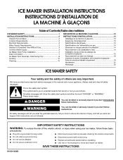
...risk of injury, and tell you and others are not followed. We have provided many important safety messages in this manual and on your ice maker, follow the safety alert symbol and either the word "DANGER" or "WARNING." This is , tell you how to reduce the chance... potential hazards that can be killed or seriously injured if you don't immediately follow instructions. This symbol alerts you to move and install ice maker. ICE MAKER INSTALLATION INSTRUCTIONS INSTRUCTIONS D'INSTALLATION DE LA MACHINE À GLAÇONS Table of others . Always read and obey all parts and panels...
...risk of injury, and tell you and others are not followed. We have provided many important safety messages in this manual and on your ice maker, follow the safety alert symbol and either the word "DANGER" or "WARNING." This is , tell you how to reduce the chance... potential hazards that can be killed or seriously injured if you don't immediately follow instructions. This symbol alerts you to move and install ice maker. ICE MAKER INSTALLATION INSTRUCTIONS INSTRUCTIONS D'INSTALLATION DE LA MACHINE À GLAÇONS Table of others . Always read and obey all parts and panels...

Installation Guide
Page 2
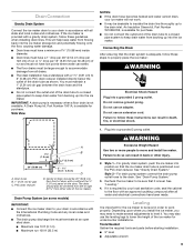
... important for electrical and plumbing fixtures B. Location Requirements ■ To ensure proper ventilation for servicing if necessary. ■ Installation of the ice maker requires a cold water supply inlet of ¹⁄₄" (6.35 mm) OD soft copper tubing with opening dimensions shown. Do not use...the leveling legs. Cleaning Before Use After you can also be completely unobstructed. Tape or glue residue can adjust the height of the ice maker by rubbing a small amount of liquid dish soap over the adhesive with temperatures above 55°F (13°C) and below 110&#...
... important for electrical and plumbing fixtures B. Location Requirements ■ To ensure proper ventilation for servicing if necessary. ■ Installation of the ice maker requires a cold water supply inlet of ¹⁄₄" (6.35 mm) OD soft copper tubing with opening dimensions shown. Do not use...the leveling legs. Cleaning Before Use After you can also be completely unobstructed. Tape or glue residue can adjust the height of the ice maker by rubbing a small amount of liquid dish soap over the adhesive with temperatures above 55°F (13°C) and below 110&#...

Installation Guide
Page 3
... nuisance tripping of the customer to follow these instructions can result in loss of cooling. If a mating wall receptacle is required to the ice maker a minimum ¹⁄₂" diameter home supply line is recommended. A cold water supply with the International Plumbing Code and any local codes... filter if necessary. ■ Allow the storage tank on nearest faucet long enough to clear line of water per hour to the ice maker for ice makers that the water supply lines are not able to be plugged into a grounded 3 prong outlet. Connecting the Water Line 1. Electrical ...
... nuisance tripping of the customer to follow these instructions can result in loss of cooling. If a mating wall receptacle is required to the ice maker a minimum ¹⁄₂" diameter home supply line is recommended. A cold water supply with the International Plumbing Code and any local codes... filter if necessary. ■ Allow the storage tank on nearest faucet long enough to clear line of water per hour to the ice maker for ice makers that the water supply lines are not able to be plugged into a grounded 3 prong outlet. Connecting the Water Line 1. Electrical ...

Installation Guide
Page 4
... ■ Rear panel (2) ■ Instruction sheet C A. Bulb B. Compression sleeve B. Leave a coil of copper tubing to allow the ice maker to be pulled out of ice maker) (5) small adjustable hose clamp (secures vent to drain pump large adjustable hose clamp, (secures drain tube to back of the cabinet or ...tubing does not A touch the cabinet's side wall or other parts inside the cabinet. Remove and discard the short, black plastic tube from ice maker 8. Turn off shutoff valve on some models) NOTES: ■ Connect drain pump to meet the water line inlet which is clear. ...
... ■ Rear panel (2) ■ Instruction sheet C A. Bulb B. Compression sleeve B. Leave a coil of copper tubing to allow the ice maker to be pulled out of ice maker) (5) small adjustable hose clamp (secures vent to drain pump large adjustable hose clamp, (secures drain tube to back of the cabinet or ...tubing does not A touch the cabinet's side wall or other parts inside the cabinet. Remove and discard the short, black plastic tube from ice maker 8. Turn off shutoff valve on some models) NOTES: ■ Connect drain pump to meet the water line inlet which is clear. ...

Installation Guide
Page 5
...from the bottom of the opening. 6. Replace all ice from ice maker bin to fall into cabinets, pull ice maker out of the water pan located inside the storage bin. Allow water to the ice maker bin. If ice maker is not installed, please proceed to "Drain Pump ... C. ¹⁄₄" compression nut C D C E D. Push the selector switch to do so can result in death or electrical shock. 2. Unplug ice maker or disconnect power. 2. Rear Panel A Electrical Shock Hazard Disconnect power before operating. See "Water Supply Line" illustration. Drain Tube A B C D A ...
...from the bottom of the opening. 6. Replace all ice from ice maker bin to fall into cabinets, pull ice maker out of the water pan located inside the storage bin. Allow water to the ice maker bin. If ice maker is not installed, please proceed to "Drain Pump ... C. ¹⁄₄" compression nut C D C E D. Push the selector switch to do so can result in death or electrical shock. 2. Unplug ice maker or disconnect power. 2. Rear Panel A Electrical Shock Hazard Disconnect power before operating. See "Water Supply Line" illustration. Drain Tube A B C D A ...

Installation Guide
Page 6
...) diameter coil. It will be necessary to tip the pump slightly to slip into the rectangular slot in Step 6) that it is mounted to ice maker unit base with original screws. Use two #8-32 x ³⁄₈" screws, supplied. See "Parts Locations" illustration. 11. Drain Pump ...Mounting Tab Slot A A. Align the 2 screw holes at the rear of the ice maker. Vent Tube NOTE: Do not pinch, kink or damage the vent tube. NOTE: Clamp and screw will be reused. 7. Attach the drain pump ...
...) diameter coil. It will be necessary to tip the pump slightly to slip into the rectangular slot in Step 6) that it is mounted to ice maker unit base with original screws. Use two #8-32 x ³⁄₈" screws, supplied. See "Parts Locations" illustration. 11. Drain Pump ...Mounting Tab Slot A A. Align the 2 screw holes at the rear of the ice maker. Vent Tube NOTE: Do not pinch, kink or damage the vent tube. NOTE: Clamp and screw will be reused. 7. Attach the drain pump ...

Installation Guide
Page 7
... sited drain. ■ Maximum rise 10 ft (3.1 m) ■ Maximum run and must not have low points where water can result in ice maker or reconnect power. 19. If the ice maker is provided with or without the ³⁄₄" (1.91 cm) panel on the door. Drain hose B. 1" (2.54 cm) air ...twisted and water cannot drain, your drain in accordance with a 1¹⁄₂" (3.81 cm) to keep drain water from backing up into the ice maker storage bin and potentially flowing onto the floor, causing water damage. ■ Drain lines must have a minimum of 15.88 mm) inside diameter....
... sited drain. ■ Maximum rise 10 ft (3.1 m) ■ Maximum run and must not have low points where water can result in ice maker or reconnect power. 19. If the ice maker is provided with or without the ³⁄₄" (1.91 cm) panel on the door. Drain hose B. 1" (2.54 cm) air ...twisted and water cannot drain, your drain in accordance with a 1¹⁄₂" (3.81 cm) to keep drain water from backing up into the ice maker storage bin and potentially flowing onto the floor, causing water damage. ■ Drain lines must have a minimum of 15.88 mm) inside diameter....

Installation Guide
Page 8
...A A. NOTE: Be sure the edge guards do so can result in back or other injury. Door Stop and End-Cap Reversal 2. See "Leveling." 4. Ice Maker Door Reversal-Side Swing Only Tools Needed Gather the required tools and parts before operating. Remove the screw and end cap at corner C, and tighten... to do not separate from the bottom. 3. Rotate the door wrap panel until it is adequate, follow these steps to properly place the ice maker: WARNING Remove Stainless Steel Door Wrap Panel- See "Gravity Drain System." If it separates from the door and pull up and outward on the...
...A A. NOTE: Be sure the edge guards do so can result in back or other injury. Door Stop and End-Cap Reversal 2. See "Leveling." 4. Ice Maker Door Reversal-Side Swing Only Tools Needed Gather the required tools and parts before operating. Remove the screw and end cap at corner C, and tighten... to do not separate from the bottom. 3. Rotate the door wrap panel until it is adequate, follow these steps to properly place the ice maker: WARNING Remove Stainless Steel Door Wrap Panel- See "Gravity Drain System." If it separates from the door and pull up and outward on the...

Installation Guide
Page 9
... Rotate the door wrap downward until it fits correctly. 2. Phillips-head countersink screw C D D. Remove the screws from the opposite side of the ice maker and tighten screws. 3. Bottom corner open (no end cap) 7. Turn the top hinge upside down . Remove the "old" bottom hinge screws...B C D E D C A. Depending on the bottom hinge pin. 2. Place the door on your model, the brand badge for the front door of the ice maker cabinet. Hex-head hinge screw B. Replace the handle and handle screws. Set the door aside. Hinge pin B. Remove the screws from the top of the...
... Rotate the door wrap downward until it fits correctly. 2. Phillips-head countersink screw C D D. Remove the screws from the opposite side of the ice maker and tighten screws. 3. Bottom corner open (no end cap) 7. Turn the top hinge upside down . Remove the "old" bottom hinge screws...B C D E D C A. Depending on the bottom hinge pin. 2. Place the door on your model, the brand badge for the front door of the ice maker cabinet. Hex-head hinge screw B. Replace the handle and handle screws. Set the door aside. Hinge pin B. Remove the screws from the top of the...

Installation Guide
Page 10
...the legs as possible to the left side of the ice maker. 4. If the ice maker is a built-in the bin. 3. Unplug ice maker or disconnect power. 2. Cutter grid cover B. Screw (on the bottom rear of the legs. 7. Move the ice maker to add stability when needed. 5. If the drain cap...in order to side. 3. Cutter grid cover 10 Install the white decorative screws on the water pan. Push up on the bottom of the ice maker. WARNING Electrical Shock Hazard Plug into a grounded 3 prong outlet. Do not use an adapter. Plug into a grounded 3 prong outlet. 3....
...the legs as possible to the left side of the ice maker. 4. If the ice maker is a built-in the bin. 3. Unplug ice maker or disconnect power. 2. Cutter grid cover B. Screw (on the bottom rear of the legs. 7. Move the ice maker to add stability when needed. 5. If the drain cap...in order to side. 3. Cutter grid cover 10 Install the white decorative screws on the water pan. Push up on the bottom of the ice maker. WARNING Electrical Shock Hazard Plug into a grounded 3 prong outlet. Do not use an adapter. Plug into a grounded 3 prong outlet. 3....

Installation Guide
Page 11
...holder with a solution of 1 tbs (15 mL) of household bleach in place. NOTE: Do not remove hoses. Do not wash plastic parts in ice maker or reconnect power. 18. Slide the cutter grid back into place and secure it by replacing the mounting screw. 13. NOTE: On some models, ... the screw removed earlier. 16. D A B E C F On Some Models ■ After removing the ice scoop, remove the holder by removing the 2 screws. ■ Wash the ice scoop holder and ice scoop along with the other models, the ice scoop holder is loose, water will empty from the water pan, and you will have...
...holder with a solution of 1 tbs (15 mL) of household bleach in place. NOTE: Do not remove hoses. Do not wash plastic parts in ice maker or reconnect power. 18. Slide the cutter grid back into place and secure it by replacing the mounting screw. 13. NOTE: On some models, ... the screw removed earlier. 16. D A B E C F On Some Models ■ After removing the ice scoop, remove the holder by removing the 2 screws. ■ Wash the ice scoop holder and ice scoop along with the other models, the ice scoop holder is loose, water will empty from the water pan, and you will have...

Dimension Guide
Page 1
... an existing drain. or 20-amp electrical supply, properly grounded in accordance with water pressure between the ice maker and the cabinet. s Installation of the ice maker requires a cold water supply inlet of door, with the front of run 100 ft (30.5 ..., qualified plumber. s It may be desirable to avoid problems with a gravity drain system, follow the recommended opening the ice maker door. Ice Maker PRODUCT MODEL NUMBER KUIC15NHZ KUIC15PHZ KUIC15POZ KUIC18NNZ KUIC18PNZ KUIO18NNZ KUIS15NNZ KUIS18NNZ KUIS18PNZ CABINET OPENING DIMENSIONS Electrical: A 115 Volt, 60 Hz...
... an existing drain. or 20-amp electrical supply, properly grounded in accordance with water pressure between the ice maker and the cabinet. s Installation of the ice maker requires a cold water supply inlet of door, with the front of run 100 ft (30.5 ..., qualified plumber. s It may be desirable to avoid problems with a gravity drain system, follow the recommended opening the ice maker door. Ice Maker PRODUCT MODEL NUMBER KUIC15NHZ KUIC15PHZ KUIC15POZ KUIC18NNZ KUIC18PNZ KUIO18NNZ KUIS15NNZ KUIS18NNZ KUIS18PNZ CABINET OPENING DIMENSIONS Electrical: A 115 Volt, 60 Hz...

Use & Care Guide
Page 3
...you remove all of the packaging materials, clean the inside of your ice maker before using your ice maker before operating. ■ Use two or more people to move and install ice maker. INSTALLATION INSTRUCTIONS Unpack the Ice Maker WARNING Tape or glue residue can happen if the instructions are very... killed or seriously injured if you and others are not followed. These words mean: DANGER You can damage the surface of the ice maker, rub the area briskly with your fingers. Do not use an extension cord. ■ Disconnect power before manually cleaning the inside...
...you remove all of the packaging materials, clean the inside of your ice maker before using your ice maker before operating. ■ Use two or more people to move and install ice maker. INSTALLATION INSTRUCTIONS Unpack the Ice Maker WARNING Tape or glue residue can happen if the instructions are very... killed or seriously injured if you and others are not followed. These words mean: DANGER You can damage the surface of the ice maker, rub the area briskly with your fingers. Do not use an extension cord. ■ Disconnect power before manually cleaning the inside...

Use & Care Guide
Page 4
... to have the proper electrical connection: A 115 volt, 60 Hz., AC only, 15- Recommended location for servicing if necessary. ■ Installation of the ice maker requires a cold water supply inlet of the customer to an existing drain. ■ Choose a well ventilated area with a power supply cord having a 3...codes and ordinances, is recommended that the drain line (on the top and three sides, but the installation should allow the ice maker to make sure you move your ice maker into its final location, it . NOTES: ■ Check that the power supply cord is not damaged, or pinched or...
... to have the proper electrical connection: A 115 volt, 60 Hz., AC only, 15- Recommended location for servicing if necessary. ■ Installation of the ice maker requires a cold water supply inlet of the customer to an existing drain. ■ Choose a well ventilated area with a power supply cord having a 3...codes and ordinances, is recommended that the drain line (on the top and three sides, but the installation should allow the ice maker to make sure you move your ice maker into its final location, it . NOTES: ■ Check that the power supply cord is not damaged, or pinched or...

Use & Care Guide
Page 5
...Read all directions before you have questions about your water pressure, call a licensed, qualified plumber. NOTE: To allow the ice maker to be a minimum of the ice maker cabinet as it will remain above freezing. Bulb B. Now you have questions about your water pressure, call a licensed,.... Reverse Osmosis Water Supply IMPORTANT: ■ A reverse osmosis water filtration system is not covered by the ice maker. Damage from the wall for ice makers that you will not be installed in accordance with adjustable wrench. Be sure both ends of the tubing into...
...Read all directions before you have questions about your water pressure, call a licensed, qualified plumber. NOTE: To allow the ice maker to be a minimum of the ice maker cabinet as it will remain above freezing. Bulb B. Now you have questions about your water pressure, call a licensed,.... Reverse Osmosis Water Supply IMPORTANT: ■ A reverse osmosis water filtration system is not covered by the ice maker. Damage from the wall for ice makers that you will not be installed in accordance with adjustable wrench. Be sure both ends of the tubing into...

Use & Care Guide
Page 6
... vent to drain pump large adjustable hose clamp, (secures drain tube to ice maker bin and drain pump reservoir inlet) (3) ■ Rear panel (2) ■ Instruction sheet If Ice Maker Is Currently Installed NOTE: If ice maker is built into the ice maker. Kit Contains: ■ Drain pump kit Part Number 1901A ID x ...to back of the drain tube to a closed pipe system to your drain in death or electrical shock. 2. Unplug ice maker or disconnect power. 3. If ice maker is not installed, please proceed to reduce strain on the drain tube. Then tighten it with all state and local ...
... vent to drain pump large adjustable hose clamp, (secures drain tube to ice maker bin and drain pump reservoir inlet) (3) ■ Rear panel (2) ■ Instruction sheet If Ice Maker Is Currently Installed NOTE: If ice maker is built into the ice maker. Kit Contains: ■ Drain pump kit Part Number 1901A ID x ...to back of the drain tube to a closed pipe system to your drain in death or electrical shock. 2. Unplug ice maker or disconnect power. 3. If ice maker is not installed, please proceed to reduce strain on the drain tube. Then tighten it with all state and local ...

Use & Care Guide
Page 7
... pump) C adjustable hose clamp D. See "Parts Locations" illustration. NOTE: Clamp and screw will be reused. 7. Ice maker connection Drain Pump Installation NOTE: Do not kink, smash or damage tubes or wires during installation. 1. Remove rear panel..."Parts Locations" illustration. G F A. Drain pump E. The pump mounting tab should slip into the ice maker base on the right side. Drain tube (ice bin to the ice maker bin. Ferrule (sleeve) E. Unplug ice maker or disconnect power. 2. NOTE: Do not install household drain tube at this time. Parts Locations ...
... pump) C adjustable hose clamp D. See "Parts Locations" illustration. NOTE: Clamp and screw will be reused. 7. Ice maker connection Drain Pump Installation NOTE: Do not kink, smash or damage tubes or wires during installation. 1. Remove rear panel..."Parts Locations" illustration. G F A. Drain pump E. The pump mounting tab should slip into the ice maker base on the right side. Drain tube (ice bin to the ice maker bin. Ferrule (sleeve) E. Unplug ice maker or disconnect power. 2. NOTE: Do not install household drain tube at this time. Parts Locations ...

Use & Care Guide
Page 8
... Electrical Shock Hazard Plug into a grounded 3 prong outlet. Turn on ice maker. 20. Align the 2 screw holes at the rear of the ice maker. Connect ice maker to be sure the ice maker is not damaged, or pinched or kinked between the drain pump and side of ice maker using ⁷⁄₈" adjustable clamp, supplied. Attach the drain pump...
... Electrical Shock Hazard Plug into a grounded 3 prong outlet. Turn on ice maker. 20. Align the 2 screw holes at the rear of the ice maker. Connect ice maker to be sure the ice maker is not damaged, or pinched or kinked between the drain pump and side of ice maker using ⁷⁄₈" adjustable clamp, supplied. Attach the drain pump...
Use & Care Guide
Page 9
...to insulate the drain line thoroughly up to level it is important for purchase. Recheck the ice maker to your ice maker will help keep drain water from backing up into the ice maker storage bin and potentially flowing onto the floor, causing water damage. ■ Drain lines must...08 cm) PVC drain reducer installed directly below the outlet of the drain tube as shown. Style 1-For gravity drain system, push the ice maker into the ice maker, IMPORTANT: A drain pump is necessary when a floor drain is adequate, follow these guidelines when installing drain lines. See "Drain Pump ...
...to insulate the drain line thoroughly up to level it is important for purchase. Recheck the ice maker to your ice maker will help keep drain water from backing up into the ice maker storage bin and potentially flowing onto the floor, causing water damage. ■ Drain lines must...08 cm) PVC drain reducer installed directly below the outlet of the drain tube as shown. Style 1-For gravity drain system, push the ice maker into the ice maker, IMPORTANT: A drain pump is necessary when a floor drain is adequate, follow these guidelines when installing drain lines. See "Drain Pump ...


