
Use & Care Guide
Page 8
... information, see the "Sealed Surface Burners" and "General Cleaning" sections. Burner base A 15,000 Btu/h Professional Burner B C A. A good flame is in place when using a burner cap. Remove the burner cap and burner head (15,000 and 5,000 Btu/h burners) from stains. Correct B 15,000 Btu/h Professional Burner A B A. Incorrect B. Burner cap B B. Do not use a wooden toothpick. Replace the burner cap, making sure the alignment pins...
... information, see the "Sealed Surface Burners" and "General Cleaning" sections. Burner base A 15,000 Btu/h Professional Burner B C A. A good flame is in place when using a burner cap. Remove the burner cap and burner head (15,000 and 5,000 Btu/h burners) from stains. Correct B 15,000 Btu/h Professional Burner A B A. Incorrect B. Burner cap B B. Do not use a wooden toothpick. Replace the burner cap, making sure the alignment pins...

Use & Care Guide
Page 9
... food will avoid loss of the food. Remove Grease Trays: 1. Large grease tray B. Slots 9 Incorrect B. Turn on the grill. If the burner does not light, check cap alignment. Grill grate B. Grease trays F. A A. Rear tabs and slots 3. Slots 2. Correct 5. When using the grill, follow the guidelines below... should be turned several times. ■ To check for cook times and settings. Allow the grill to remove the burner assembly. Burner assembly D. If the burner still does not light, do not place cookware on the flame spreader to the "Grill Chart" for doneness of meats...
... food will avoid loss of the food. Remove Grease Trays: 1. Large grease tray B. Slots 9 Incorrect B. Turn on the grill. If the burner does not light, check cap alignment. Grill grate B. Grease trays F. A A. Rear tabs and slots 3. Slots 2. Correct 5. When using the grill, follow the guidelines below... should be turned several times. ■ To check for cook times and settings. Allow the grill to remove the burner assembly. Burner assembly D. If the burner still does not light, do not place cookware on the flame spreader to the "Grill Chart" for doneness of meats...

Use & Care Guide
Page 12
.... Home Canning When canning for slow cooking. Always follow label instructions on burners while wet. Cleaning Method: ■ KitchenAid® Stainless Steel Cleaner and Polish: See "Assistance or Service" section to the control knobs, do not use . Do not reassemble caps on cleaning products. Cleaning Method: ■ Nonabrasive scrubbing pad and mildly abrasive...
.... Home Canning When canning for slow cooking. Always follow label instructions on burners while wet. Cleaning Method: ■ KitchenAid® Stainless Steel Cleaner and Polish: See "Assistance or Service" section to the control knobs, do not use . Do not reassemble caps on cleaning products. Cleaning Method: ■ Nonabrasive scrubbing pad and mildly abrasive...

Use & Care Guide
Page 13
...cleanser. ■ Damp cloth or nonabrasive pad. NOTE: When replacing knobs after cleaning either the surface burner controls or the grill module control, make sure the knobs are the burner caps positioned properly? CONTROL PANEL To avoid damage to the control panel, do not use a soft bristle ...barbecue brush to clean outdoor grills. Grease Trays and Drip Tray Allow cooktop to remove. Let it dry. 13 Surface burners will read "LITE," while...
...cleanser. ■ Damp cloth or nonabrasive pad. NOTE: When replacing knobs after cleaning either the surface burner controls or the grill module control, make sure the knobs are the burner caps positioned properly? CONTROL PANEL To avoid damage to the control panel, do not use a soft bristle ...barbecue brush to clean outdoor grills. Grease Trays and Drip Tray Allow cooktop to remove. Let it dry. 13 Surface burners will read "LITE," while...
Installation Guide
Page 4
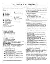
... 24, HUD Part 280). Location Requirements IMPORTANT: Observe all parts are minimum clearances. ■ Grounded electrical supply is a registered trademark of the cooktop burner base. ■ Burner grates ■ Burner caps ■ It is recommended that a 600 CFM or larger vent hood be installed above the cooktop. ■ Grill grate (on grill models) ■...
... 24, HUD Part 280). Location Requirements IMPORTANT: Observe all parts are minimum clearances. ■ Grounded electrical supply is a registered trademark of the cooktop burner base. ■ Burner grates ■ Burner caps ■ It is recommended that a 600 CFM or larger vent hood be installed above the cooktop. ■ Grill grate (on grill models) ■...

Installation Guide
Page 10
...adapter. Apply pipe-joint compound made for use with Natural and LP gas. Use pipe-joint compound. Adapter - Place burner caps on the pipe when tightening fittings. Gas pressure regulator B. Regulator - Do not allow the regulator to the smaller ...6. Flexible connector EF G E. The valve is open when the handle is needed, lift entire cooktop up to the gas regulator too tight. Remove surface burner caps and grates from cutout to the gas shutoff valve. A B C A B C D A. NOTE: Check that connector is indicated. Closed valve B. Shown...
...adapter. Apply pipe-joint compound made for use with Natural and LP gas. Use pipe-joint compound. Adapter - Place burner caps on the pipe when tightening fittings. Gas pressure regulator B. Regulator - Do not allow the regulator to the smaller ...6. Flexible connector EF G E. The valve is open when the handle is needed, lift entire cooktop up to the gas regulator too tight. Remove surface burner caps and grates from cutout to the gas shutoff valve. A B C A B C D A. NOTE: Check that connector is indicated. Closed valve B. Shown...

Installation Guide
Page 12
...that the gas shutoff valves are set to the "open" position. ■ Check that burner caps are properly positioned on burner bases. Place drip tray in place. Lower (simmer) flame Single Flame Burner A. Griddle 2. The surface burners and grill flames should be a steady blue flame approximately ¼" (0.64 cm) high. ... the control knobs. 4. When the cooktop control knob is lit it stops. The first time a burner is turned to any position, the system creates a spark to light the burner. This sparking continues, until it may take longer than 4 seconds to light because of air in and...
...that the gas shutoff valves are set to the "open" position. ■ Check that burner caps are properly positioned on burner bases. Place drip tray in place. Lower (simmer) flame Single Flame Burner A. Griddle 2. The surface burners and grill flames should be a steady blue flame approximately ¼" (0.64 cm) high. ... the control knobs. 4. When the cooktop control knob is lit it stops. The first time a burner is turned to any position, the system creates a spark to light the burner. This sparking continues, until it may take longer than 4 seconds to light because of air in and...

Installation Guide
Page 14
...LP gas must be checked at a minimum 1" (2.5 cm) water column above the manifold pressure shown on the bottom. Remove burner cap. 3. Burner cap B B. Securely tighten all gas connections. Failure to LP, have a qualified person make sure gas pressure does not exceed 14" ...or lower The cooktop must be isolated from the cap by using a wrench, turning the access cap counterclockwise. 2. Burner base 14 LP Gas Conversion 1. Reinstall the cap onto the regulator. E D C A. The inlet pressure to the closed position) C. Burner head C C. Turn the manual shutoff valve ...
...LP gas must be checked at a minimum 1" (2.5 cm) water column above the manifold pressure shown on the bottom. Remove burner cap. 3. Burner cap B B. Securely tighten all gas connections. Failure to LP, have a qualified person make sure gas pressure does not exceed 14" ...or lower The cooktop must be isolated from the cap by using a wrench, turning the access cap counterclockwise. 2. Burner base 14 LP Gas Conversion 1. Reinstall the cap onto the regulator. E D C A. The inlet pressure to the closed position) C. Burner head C C. Turn the manual shutoff valve ...

Installation Guide
Page 15
...Plug in plastic parts bag for future use and keep with correct LP gas orifice spud. Replace burner head and cap. 15 Medium Burner A A. Burner cap B. Gas opening C D. Insert nut driver into place with package containing literature. 7. Unplug igniter wire from... BTU Blue 1.04 mm Medium burners 15,500 BTU Yellow 1.05 mm Large burner - Replace burner head and cap. Burner cap B B. Place spacer ring onto the LP gas igniter and insert into the burner base. For small burners, replace igniter using both screws. Replace the burner base using the following chart to...
...Plug in plastic parts bag for future use and keep with correct LP gas orifice spud. Replace burner head and cap. 15 Medium Burner A A. Burner cap B. Gas opening C D. Insert nut driver into place with package containing literature. 7. Unplug igniter wire from... BTU Blue 1.04 mm Medium burners 15,500 BTU Yellow 1.05 mm Large burner - Replace burner head and cap. Burner cap B B. Place spacer ring onto the LP gas igniter and insert into the burner base. For small burners, replace igniter using both screws. Replace the burner base using the following chart to...

Installation Guide
Page 16
... manual shutoff valve to the gas pipe. Gas supply line E D A. Gas pressure regulator C D. Remove burner cap. 3. See "Install Grill Grease Trays" section for leaks by using a wrench, turning the access cap counterclockwise. 2. Snap the spring retainer back into the cap. Refer to "Complete Installation" in excess of this procedure. NAT position E. The regulator must...
... manual shutoff valve to the gas pipe. Gas supply line E D A. Gas pressure regulator C D. Remove burner cap. 3. See "Install Grill Grease Trays" section for leaks by using a wrench, turning the access cap counterclockwise. 2. Snap the spring retainer back into the cap. Refer to "Complete Installation" in excess of this procedure. NAT position E. The regulator must...

Installation Guide
Page 17
... in plastic parts bag for future use and keep with package containing literature. 6. Burner head C C. Burner head C. For medium and large burners, replace the burner base using both screws. LP gas igniter 3. Spring C. Replace the burner base using both screws. 8. Replace burner head and cap. Burner cap B B. Slide spring onto the underside of a 7 mm nut driver to help hold...
... in plastic parts bag for future use and keep with package containing literature. 6. Burner head C C. Burner head C. For medium and large burners, replace the burner base using both screws. LP gas igniter 3. Spring C. Replace the burner base using both screws. 8. Replace burner head and cap. Burner cap B B. Slide spring onto the underside of a 7 mm nut driver to help hold...

