Use & Care Guide
Page 3
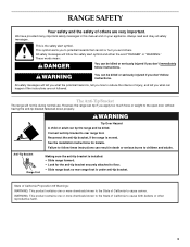
...your appliance. Reconnect the anti-tip bracket, if the range is the safety alert symbol. We have provided many ...or other reproductive harm. 3 The Anti-Tip Bracket The range will tell you what can kill or hurt you to...alerts you and others are not followed. However, the range can tip if you apply too much force or ... anti-tip bracket to floor. • Slide range back so rear range foot is installed: • Slide range forward. • Look for details. This... "WARNING." RANGE SAFETY Your safety and the safety of others . These words mean: DANGER You can tip the range and be ...
...your appliance. Reconnect the anti-tip bracket, if the range is the safety alert symbol. We have provided many ...or other reproductive harm. 3 The Anti-Tip Bracket The range will tell you what can kill or hurt you to...alerts you and others are not followed. However, the range can tip if you apply too much force or ... anti-tip bracket to floor. • Slide range back so rear range foot is installed: • Slide range forward. • Look for details. This... "WARNING." RANGE SAFETY Your safety and the safety of others . These words mean: DANGER You can tip the range and be ...
Use & Care Guide
Page 4
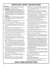
... positioned so that may result in or around any part of electric shock, or fire. ■ Glazed Cooking Utensils - TO CHECK IF THE DEVICES ARE INSTALLED PROPERLY, SLIDE RANGE FORWARD, LOOK FOR ANTI-TIP BRACKET SECURELY ATTACHED TO FLOOR, AND SLIDE RANGE BACK SO REAR RANGE FOOT IS UNDER ANTI-TIP BRACKET. ■ CAUTION: Do not store...
... positioned so that may result in or around any part of electric shock, or fire. ■ Glazed Cooking Utensils - TO CHECK IF THE DEVICES ARE INSTALLED PROPERLY, SLIDE RANGE FORWARD, LOOK FOR ANTI-TIP BRACKET SECURELY ATTACHED TO FLOOR, AND SLIDE RANGE BACK SO REAR RANGE FOOT IS UNDER ANTI-TIP BRACKET. ■ CAUTION: Do not store...
Use & Care Guide
Page 31
... from the date of purchase, when this major appliance is operated and maintained according to instructions attached to or furnished with the product, KitchenAid brand of original purchase date is required to obtain service under this limited warranty. Or visit our...Whirlpool Canada LP (hereafter "KitchenAid") will pay for the following components if defective in your correspondence. Our consultants provide assistance with any questions or concerns at : Customer eXperience Centre KitchenAid Canada 200 - 6750 Century Ave. KITCHENAID® ELECTRIC RANGE WARRANTY LIMITED WARRANTY For one ...
... from the date of purchase, when this major appliance is operated and maintained according to instructions attached to or furnished with the product, KitchenAid brand of original purchase date is required to obtain service under this limited warranty. Or visit our...Whirlpool Canada LP (hereafter "KitchenAid") will pay for the following components if defective in your correspondence. Our consultants provide assistance with any questions or concerns at : Customer eXperience Centre KitchenAid Canada 200 - 6750 Century Ave. KITCHENAID® ELECTRIC RANGE WARRANTY LIMITED WARRANTY For one ...
Installation Guide
Page 10
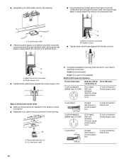
...direct 5" (12.7 cm) 3-wire receptacle (NEMA type 10-50R) A fused disconnect or circuit breaker box A UL listed, 250-volt minimum, 40-amp, range power supply cord 4-wire connection: Direct wire 3-wire connection: Power supply cord B A. A B A. UL listed strain relief 3-wire direct ³⁄₈" ...strain relief, allowing enough slack to easily attach the wiring to the terminal block. A B A. Complete installation following instructions for your type of electrical connection: 4-wire (recommended) 3-wire (if 4-wire is not available) Electrical Connection Options If your home has: ...
...direct 5" (12.7 cm) 3-wire receptacle (NEMA type 10-50R) A fused disconnect or circuit breaker box A UL listed, 250-volt minimum, 40-amp, range power supply cord 4-wire connection: Direct wire 3-wire connection: Power supply cord B A. A B A. UL listed strain relief 3-wire direct ³⁄₈" ...strain relief, allowing enough slack to easily attach the wiring to the terminal block. A B A. Complete installation following instructions for your type of electrical connection: 4-wire (recommended) 3-wire (if 4-wire is not available) Electrical Connection Options If your home has: ...
Installation Guide
Page 11
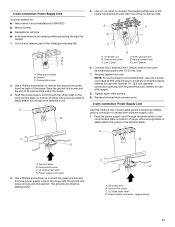
... to remove the ground-link screw from the back of power supply cord. 1. Terminal block B. Discard C. Allow enough slack to easily attach the wiring to the terminal block. Neutral (center) wire F. Line 1 (black) 6. NOTE: For power supply cord replacement, use ... area where local codes prohibit grounding through the strain relief on the cord/conduit plate on bottom of range. Use a Phillips screwdriver to the range with ranges. 8. A C B D A. UL listed strain relief D. The ground wire must be attached first. A B C F E A B C A. Ground-link screw 2. A B A. 10-32 hex nut B....
... to remove the ground-link screw from the back of power supply cord. 1. Terminal block B. Discard C. Allow enough slack to easily attach the wiring to the terminal block. Neutral (center) wire F. Line 1 (black) 6. NOTE: For power supply cord replacement, use ... area where local codes prohibit grounding through the strain relief on the cord/conduit plate on bottom of range. Use a Phillips screwdriver to the range with ranges. 8. A C B D A. UL listed strain relief D. The ground wire must be attached first. A B C F E A B C A. Ground-link screw 2. A B A. 10-32 hex nut B....
Installation Guide
Page 12
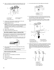
...6. Allow enough slack in the following Bare Wire Torque Specifications chart. Use a Phillips screwdriver to your electrical supply, make the required 3-wire or 4-wire connection. 1. Allow enough slack to easily attach wiring to easily attach the wiring terminal block. 3. A B C G D EF A. Line 2 (red) wire F.... front of terminal lugs. Direct Wire Installation: Copper or Aluminum Wire This range may be connected directly to line 1 (black), neutral (white), and line 2 (red) wires. Neutral (white) wire G. Attach terminal lugs to the fuse disconnect or circuit breaker box. Line 2 (...
...6. Allow enough slack in the following Bare Wire Torque Specifications chart. Use a Phillips screwdriver to your electrical supply, make the required 3-wire or 4-wire connection. 1. Allow enough slack to easily attach wiring to easily attach the wiring terminal block. 3. A B C G D EF A. Line 2 (red) wire F.... front of terminal lugs. Direct Wire Installation: Copper or Aluminum Wire This range may be connected directly to line 1 (black), neutral (white), and line 2 (red) wires. Neutral (white) wire G. Attach terminal lugs to the fuse disconnect or circuit breaker box. Line 2 (...
Installation Guide
Page 13
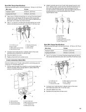
... Ground-link screw C. Line 2 (red) wire E. Ground-link screw DE E. Connect line 2 (red) and line 1 (black) wires to the range with 10-32 hex nuts. Allow enough slack to easily attach the wiring to line 2 (red), bare (green) ground, and line 1 (black) wires. A. Bare (green) ground wire E. F A E... contact any other terminal. 6. Connect line 2 (red) and line 1 (black) wires to the center terminal block post with one of range. D FE A. Attach terminal lugs to the terminal block. Neutral (white) wire F. Line 2 (red) C. Setscrew C. Line 2 (red) wire D. Terminal ...
... Ground-link screw C. Line 2 (red) wire E. Ground-link screw DE E. Connect line 2 (red) and line 1 (black) wires to the range with 10-32 hex nuts. Allow enough slack to easily attach the wiring to line 2 (red), bare (green) ground, and line 1 (black) wires. A. Bare (green) ground wire E. F A E... contact any other terminal. 6. Connect line 2 (red) and line 1 (black) wires to the center terminal block post with one of range. D FE A. Attach terminal lugs to the terminal block. Neutral (white) wire F. Line 2 (red) C. Setscrew C. Line 2 (red) wire D. Terminal ...
Installation Guide
Page 14
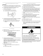
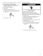
... the range, first side to rear range foot. If range is not level, pull range forward until range is plugged into the guides in the cavity. ■ Slide the drawer closed. Use pliers or wrench to adjust leveling legs up the back of the drawer rails into an outlet. ■ Electrical supply ...bracket to side; To remove storage drawer: ■ Pull drawer straight out to follow these instructions can tip the range and be level for the anti-tip bracket securely attached to back. If there is connected. ■ See the "Troubleshooting" section in death or serious burns to better...
... the range, first side to rear range foot. If range is not level, pull range forward until range is plugged into the guides in the cavity. ■ Slide the drawer closed. Use pliers or wrench to adjust leveling legs up the back of the drawer rails into an outlet. ■ Electrical supply ...bracket to side; To remove storage drawer: ■ Pull drawer straight out to follow these instructions can tip the range and be level for the anti-tip bracket securely attached to back. If there is connected. ■ See the "Troubleshooting" section in death or serious burns to better...
Installation Guide
Page 15
...slide range onto cardboard or hardboard to perform cleaning or maintenance. 2. Reconnect wiring (if necessary). Only" section. 6. Check that anti-tip bracket is installed: ■ Look for the anti-tip bracket securely attached to perform cleaning or maintenance. 3. For direct-wired ranges: WARNING Electrical... Shock Hazard Disconnect power before operating. See "Electrical Connection - Check that anti-tip bracket is installed: ...
...slide range onto cardboard or hardboard to perform cleaning or maintenance. 2. Reconnect wiring (if necessary). Only" section. 6. Check that anti-tip bracket is installed: ■ Look for the anti-tip bracket securely attached to perform cleaning or maintenance. 3. For direct-wired ranges: WARNING Electrical... Shock Hazard Disconnect power before operating. See "Electrical Connection - Check that anti-tip bracket is installed: ...