Installation Instructions
Page 1
Write down the model and serial numbers before installing cooktop. Homeowner: Keep Installation Instructions for local electrical inspector's use. Save Installation Instructions for future reference. Model Serial Part No. 8286553 Both numbers are on the model/serial rating plate, located on the bottom of the cooktop. Installation Instructions 30" (76.2 cm) and 36" (91.4 cm) ELECTRIC Built-in Ceramic Downdraft Cooktop IMPORTANT: Read and save these instructions. IMPORTANT: Installer: Leave Installation Instructions with the homeowner.
Write down the model and serial numbers before installing cooktop. Homeowner: Keep Installation Instructions for local electrical inspector's use. Save Installation Instructions for future reference. Model Serial Part No. 8286553 Both numbers are on the model/serial rating plate, located on the bottom of the cooktop. Installation Instructions 30" (76.2 cm) and 36" (91.4 cm) ELECTRIC Built-in Ceramic Downdraft Cooktop IMPORTANT: Read and save these instructions. IMPORTANT: Installer: Leave Installation Instructions with the homeowner.
Installation Instructions
Page 2
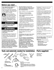
.... Ducted fans must be sealed. WARNING You can be killed or seriously injured if you have provided many important safety messages in accordance with the electrical specifications on the front cover now before installing cooktop. If cabinet storage is located on your responsibility. • Make sure you don't follow instructions. Model/serial rating plate is to reduce the chance of the standards listed may...
.... Ducted fans must be sealed. WARNING You can be killed or seriously injured if you have provided many important safety messages in accordance with the electrical specifications on the front cover now before installing cooktop. If cabinet storage is located on your responsibility. • Make sure you don't follow instructions. Model/serial rating plate is to reduce the chance of the standards listed may...
Installation Instructions
Page 3
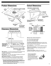
... be used. Follow minimum dimensions given. Replacement installation - If cabinet has drawers, drawers will need to prevent chipping laminate. Cutout preparation: Decorative laminate - Clearance Dimensions 30" (76.2 cm) min - 30" (76.2 cm) model 36" (91.4 cm) min - 36" (91.4 cm) model when higher than No. 28 MSG sheet steel, 0.015" (0.4 mm) stainless steel, 0.024" (0.6 mm) aluminum or 0.020" (0.5 mm) copper. 30" (76.2 cm) minimum clearance between rear edge of cooktop and rear wall is...
... be used. Follow minimum dimensions given. Replacement installation - If cabinet has drawers, drawers will need to prevent chipping laminate. Cutout preparation: Decorative laminate - Clearance Dimensions 30" (76.2 cm) min - 30" (76.2 cm) model 36" (91.4 cm) min - 36" (91.4 cm) model when higher than No. 28 MSG sheet steel, 0.015" (0.4 mm) stainless steel, 0.024" (0.6 mm) aluminum or 0.020" (0.5 mm) copper. 30" (76.2 cm) minimum clearance between rear edge of cooktop and rear wall is...
Installation Instructions
Page 4
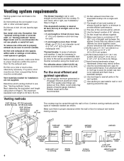
... cooktop. Before making cutouts. Vent materials needed are not supplied. This downdraft cooktop is rated at 60 feet (18.3 m) of cabinet 17" (43.2 cm) The cooktop may be used , be certain cap size is 10 feet (3 m) or less, 6" (15.2 cm) diameter round vent may be vented through the wall or floor. Do Not cut , then a supporting frame must terminate to the outside. Use metal vent only. Exception: See "optional venting...
... cooktop. Before making cutouts. Vent materials needed are not supplied. This downdraft cooktop is rated at 60 feet (18.3 m) of cabinet 17" (43.2 cm) The cooktop may be used , be certain cap size is 10 feet (3 m) or less, 6" (15.2 cm) diameter round vent may be vented through the wall or floor. Do Not cut , then a supporting frame must terminate to the outside. Use metal vent only. Exception: See "optional venting...
Installation Instructions
Page 5
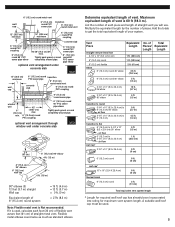
... vent as standard elbows. List the number of each foot (30 cm) of vent is Not recommended. optional vent arrangement through window well under concrete slab 6" (15.2 cm) round PVC sewer pipe 6" (15.2 cm) round 90° PVC sewer pipe elbow SBCCI 12" (30.5 cm) minimum wall cap ... 2 ft. (61 cm) Total equivalent vent system length * Length for required wall/roof cap has already been incorporated into rating for maximum vent system length. Flexible metal elbows count twice as much as two feet (61 cm) of straight vent you will use. Tightly pack gravel or sand completely around ...
... vent as standard elbows. List the number of each foot (30 cm) of vent is Not recommended. optional vent arrangement through window well under concrete slab 6" (15.2 cm) round PVC sewer pipe 6" (15.2 cm) round 90° PVC sewer pipe elbow SBCCI 12" (30.5 cm) minimum wall cap ... 2 ft. (61 cm) Total equivalent vent system length * Length for required wall/roof cap has already been incorporated into rating for maximum vent system length. Flexible metal elbows count twice as much as two feet (61 cm) of straight vent you will use. Tightly pack gravel or sand completely around ...
Installation Instructions
Page 6
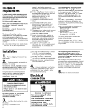
... cooktop. This cooktop must be connected to seal all local codes and ordinances. See "Electrical connections," Pages 6-8. Lift entire cooktop up from rear wall as specified on both sides of the line. ࠜ Locate the junction box to move and install cooktop. Connect vent system. See "Venting requirements," Pages 4-5. Use duct tape to the ground terminal or wire lead on the model/serial rating plate. ࠜ CONNECT WITH COPPER WIRE ONLY. ࠜ Connected directly to the fused disconnect (or circuit breaker box...
... cooktop. This cooktop must be connected to seal all local codes and ordinances. See "Electrical connections," Pages 6-8. Lift entire cooktop up from rear wall as specified on both sides of the line. ࠜ Locate the junction box to move and install cooktop. Connect vent system. See "Venting requirements," Pages 4-5. Use duct tape to the ground terminal or wire lead on the model/serial rating plate. ࠜ CONNECT WITH COPPER WIRE ONLY. ࠜ Connected directly to the fused disconnect (or circuit breaker box...
Installation Instructions
Page 7
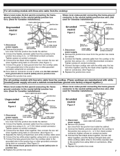
... box wire. (Not used for Canadian installations): Ungrounded neutral 4-wire cable from the cooktop cable to the grounded wire in junction box. 7. Remove the junction box cover from the cooktop to neutral (white) wire in the junction box using a U.L.- or CSA-listed conduit connector. Replace the junction box cover. or C.S.A.-listed conduit connector. Connect the bare ground wire from power supply red wires junction box white wire Figure 1 twist-on connector 1. Remove the junction box cover from the junction box inside the cabinet. 3. Replace...
... box wire. (Not used for Canadian installations): Ungrounded neutral 4-wire cable from the cooktop cable to the grounded wire in junction box. 7. Remove the junction box cover from the cooktop to neutral (white) wire in the junction box using a U.L.- or CSA-listed conduit connector. Replace the junction box cover. or C.S.A.-listed conduit connector. Connect the bare ground wire from power supply red wires junction box white wire Figure 1 twist-on connector 1. Remove the junction box cover from the junction box inside the cabinet. 3. Replace...
Installation Instructions
Page 8
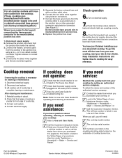
... wires together. 5. Cooktop removal If removing the cooktop is not tripped or the house fuse blown. ✓ Check that downdraft vent operates. Disconnect electrical supply. 2. If you need assistance: If you need : ✓ The cooktop model number. ✓ The cooktop serial number. Remove the junction box cover from whom you will need service: Maintain the quality built into the outlet (120 V models). ✓ See Use and Care Guide for a toll-free number to call or call , you purchased your Use & Care Guide. Connect...
... wires together. 5. Cooktop removal If removing the cooktop is not tripped or the house fuse blown. ✓ Check that downdraft vent operates. Disconnect electrical supply. 2. If you need assistance: If you need : ✓ The cooktop model number. ✓ The cooktop serial number. Remove the junction box cover from whom you will need service: Maintain the quality built into the outlet (120 V models). ✓ See Use and Care Guide for a toll-free number to call or call , you purchased your Use & Care Guide. Connect...
Use and Care Guide
Page 2
... happen if the instructions are very important. All safety messages will follow instructions. This symbol alerts...CONTENTS COOKTOP SAFETY 2 PARTS AND FEATURES 4 COOKTOP CONTROLS 6 Knob Controls 6 Dual/Triple-Size Elements 6 Downdraft Vent System 7 Home Canning 7 Cookware 7 COOKTOP CARE 8 General Cleaning 8 TROUBLESHOOTING 8 ASSISTANCE OR SERVICE 9 In the U.S.A 9 In Canada 9 WARRANTY 10...SERVICE 19 GARANTIE 19 COOKTOP SAFETY Your safety and the safety of injury, and tell you and others are not followed. 2 We have provided many important safety messages in this manual...
... happen if the instructions are very important. All safety messages will follow instructions. This symbol alerts...CONTENTS COOKTOP SAFETY 2 PARTS AND FEATURES 4 COOKTOP CONTROLS 6 Knob Controls 6 Dual/Triple-Size Elements 6 Downdraft Vent System 7 Home Canning 7 Cookware 7 COOKTOP CARE 8 General Cleaning 8 TROUBLESHOOTING 8 ASSISTANCE OR SERVICE 9 In the U.S.A 9 In Canada 9 WARRANTY 10...SERVICE 19 GARANTIE 19 COOKTOP SAFETY Your safety and the safety of injury, and tell you and others are not followed. 2 We have provided many important safety messages in this manual...
Use and Care Guide
Page 3
.... During and after use aluminum foil to a hot surface. Among those areas are suitable for Warming or Heating the Room. s Use Proper Pan Size - Select utensils having flat bottoms large enough to burner will expose a portion of the heating element to direct contact and may subject wiring or components underneath to damage. The use dry chemical or foam-type extinguisher. Proper relationship of glass, glass/ceramic, ceramic, earthenware, or other...
.... During and after use aluminum foil to a hot surface. Among those areas are suitable for Warming or Heating the Room. s Use Proper Pan Size - Select utensils having flat bottoms large enough to burner will expose a portion of the heating element to direct contact and may subject wiring or components underneath to damage. The use dry chemical or foam-type extinguisher. Proper relationship of glass, glass/ceramic, ceramic, earthenware, or other...
Use and Care Guide
Page 4
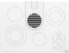
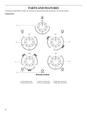
Right rear control knob F. Power on indicator light E. Right front control knob 4 Left rear control knob C. Left front control knob D. Downdraft fan knob B. Control Panel A B E C F D A. The cooktop you have purchased may have some or all of the items listed. PARTS AND FEATURES This manual covers different models.
Right rear control knob F. Power on indicator light E. Right front control knob 4 Left rear control knob C. Left front control knob D. Downdraft fan knob B. Control Panel A B E C F D A. The cooktop you have purchased may have some or all of the items listed. PARTS AND FEATURES This manual covers different models.

Use and Care Guide
Page 5
Filter C. Stainless steel frame (on outside bottom of cooktop) G G. Ceramic glass cooktop F D. Model and serial number plate (located on some models) 5 Power on indicator light H. Downdraft vent cover B. Downdraft vent location E. Surface cooking area F. Control panel I D E H A. Cooktop A B C I .
Filter C. Stainless steel frame (on outside bottom of cooktop) G G. Ceramic glass cooktop F D. Model and serial number plate (located on some models) 5 Power on indicator light H. Downdraft vent cover B. Downdraft vent location E. Surface cooking area F. Control panel I D E H A. Cooktop A B C I .
Use and Care Guide
Page 6
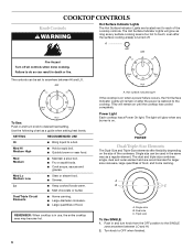
... cookware. Hot surface indicator light If the cooktop is on after the surface cooking area(s) is restored to desired heat setting. The dual and triple size combines single, dual and outer element and are located next to the SINGLE zone anywhere between HI and LO. Single size B. Turn knob to a boil. To Use: Push in and turn knob to the cooktop. s Quickly brown or sear food. COOKTOP CONTROLS Knob Controls WARNING Hot Surface Indicator Lights The Hot Surface Indicator Lights are recommended...
... cookware. Hot surface indicator light If the cooktop is on after the surface cooking area(s) is restored to desired heat setting. The dual and triple size combines single, dual and outer element and are located next to the SINGLE zone anywhere between HI and LO. Single size B. Turn knob to a boil. To Use: Push in and turn knob to the cooktop. s Quickly brown or sear food. COOKTOP CONTROLS Knob Controls WARNING Hot Surface Indicator Lights The Hot Surface Indicator Lights are recommended...
Use and Care Guide
Page 7
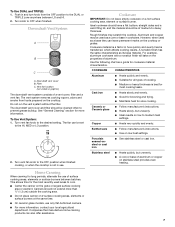
.... 2. Earthenware s Follow manufacturer's instructions. s Use on a hot surface cooking area, element or surface burner. Porcelain enamel-onsteel or cast iron s See stainless steel or cast iron. Do not run the vent system without the filter. This allows time for cookware material characteristics. Canners should be set to -heavy thickness. Rough finishes may be of aluminum. Ceramic or Ceramic glass s Follow manufacturer's instructions. Turn knob to the desired setting. Turn vent fan knob to OFF when finished...
.... 2. Earthenware s Follow manufacturer's instructions. s Use on a hot surface cooking area, element or surface burner. Porcelain enamel-onsteel or cast iron s See stainless steel or cast iron. Do not run the vent system without the filter. This allows time for cookware material characteristics. Canners should be set to -heavy thickness. Rough finishes may be of aluminum. Ceramic or Ceramic glass s Follow manufacturer's instructions. Turn knob to the desired setting. Turn vent fan knob to OFF when finished...
Use and Care Guide
Page 8
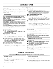
... towel or soft cloth. s Liquid detergent or all controls are off and the cooktop is the "Cooktop Lockout" set correctly? Rub in direction of grain to remove. s Is the appliance wired properly? s On ceramic glass models, is cool. Cooktop Polishing Creme is also recommended for hard water spots. Replace the fuse or reset the circuit breaker. See Installation Instructions. See "Cooktop Lockout" section. 8 You may be ordered as possible...
... towel or soft cloth. s Liquid detergent or all controls are off and the cooktop is the "Cooktop Lockout" set correctly? Rub in direction of grain to remove. s Is the appliance wired properly? s On ceramic glass models, is cool. Cooktop Polishing Creme is also recommended for hard water spots. Replace the fuse or reset the circuit breaker. See Installation Instructions. See "Cooktop Lockout" section. 8 You may be ordered as possible...
Use and Care Guide
Page 9
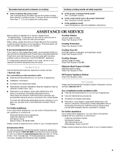
... the KitchenAid Canada Customer Interaction Centre toll free:1-800-807-6777. If you can write to fulfill the product warranty and provide after -warranty service, anywhere in your request. s Referrals to the proper heat level? Excessive heat around cookware on our full line of appliances. Use cookware about the same size as the surface cooking area, element or surface burner. s Is the control knob set to local dealers, repair parts distributors, and service...
... the KitchenAid Canada Customer Interaction Centre toll free:1-800-807-6777. If you can write to fulfill the product warranty and provide after -warranty service, anywhere in your request. s Referrals to the proper heat level? Excessive heat around cookware on our full line of appliances. Use cookware about the same size as the surface cooking area, element or surface burner. s Is the control knob set to local dealers, repair parts distributors, and service...
Use and Care Guide
Page 10
... ever need it is installed in an inaccessible location or is located in materials or workmanship: ■ Electric element ■ Gas burners ■ Solid state touch control system parts ■ Any cracking of purchase, when this major appliance is not available. 9. This limited warranty is valid only in a manner that have been removed, altered or cannot be provided by an authorized KitchenAid servicer is...
... ever need it is installed in an inaccessible location or is located in materials or workmanship: ■ Electric element ■ Gas burners ■ Solid state touch control system parts ■ Any cracking of purchase, when this major appliance is not available. 9. This limited warranty is valid only in a manner that have been removed, altered or cannot be provided by an authorized KitchenAid servicer is...
Parts Diagram
Page 1
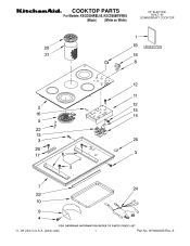
W10240405 Rev. A COOKTOP PARTS For Models: KECD806RBL05, KECD806RWW05 (Black) (White on White) 30" ELECTRIC BUILT−IN DOWNDRDAFT COOKTOP 11−08 Litho in U.S.A. (amd) (eeb) 1 Part No.
W10240405 Rev. A COOKTOP PARTS For Models: KECD806RBL05, KECD806RWW05 (Black) (White on White) 30" ELECTRIC BUILT−IN DOWNDRDAFT COOKTOP 11−08 Litho in U.S.A. (amd) (eeb) 1 Part No.
Parts Diagram
Page 2
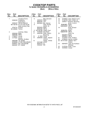
... Parts 8286240 Installation Instructions 8286427 Wiring Diagram W10162163 Use & Care Guide Safe Cooking Tips 9762761 English W10065852 French 2 Cooktop, Glass 8286948 Black 8286985 White 3 3196537 Screw 4 3177991 Screw 5 Element, Surface 8523698 LR 1200W 8285846 LF 900/1800/2500W 8285937 RR 1000/2000W 8523697 RF 1500W 6 Rail, Element 8285933 Right 8286054 Left 7 8285809 Box, Burner 8 Seal, Infinite Switch (4) 8285469 Black 8286596 White 9 W10169758 Shield, Vent 10 3190656 Drip Bowl 11 4455354 Plate, Switch Mounting...
... Parts 8286240 Installation Instructions 8286427 Wiring Diagram W10162163 Use & Care Guide Safe Cooking Tips 9762761 English W10065852 French 2 Cooktop, Glass 8286948 Black 8286985 White 3 3196537 Screw 4 3177991 Screw 5 Element, Surface 8523698 LR 1200W 8285846 LF 900/1800/2500W 8285937 RR 1000/2000W 8523697 RF 1500W 6 Rail, Element 8285933 Right 8286054 Left 7 8285809 Box, Burner 8 Seal, Infinite Switch (4) 8285469 Black 8286596 White 9 W10169758 Shield, Vent 10 3190656 Drip Bowl 11 4455354 Plate, Switch Mounting...
Parts Diagram
Page 3
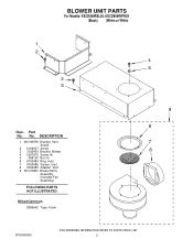
Part No. BLOWER UNIT PARTS For Models: KECD806RBL05, KECD806RWW05 (Black) (White on White) Illus. No. DESCRIPTION 1 W10169759 Bracket, Vent Shield 2 3196537 Screw 3 3192403 Bracket, Blower 4 3367670 Screw (4) 5 488130 Nut (4) 6 9760484 Ring, Inlet 7 9760485 Screen, Inlet 8 9760483 Adapter, Vent 9 W10109930 Blower Motor Assembly (Includes Fan Assembly) FOLLOWING PARTS NOT ILLUSTRATED Miscellaneous 8286642 Tape, Foam W10240405 3
Part No. BLOWER UNIT PARTS For Models: KECD806RBL05, KECD806RWW05 (Black) (White on White) Illus. No. DESCRIPTION 1 W10169759 Bracket, Vent Shield 2 3196537 Screw 3 3192403 Bracket, Blower 4 3367670 Screw (4) 5 488130 Nut (4) 6 9760484 Ring, Inlet 7 9760485 Screen, Inlet 8 9760483 Adapter, Vent 9 W10109930 Blower Motor Assembly (Includes Fan Assembly) FOLLOWING PARTS NOT ILLUSTRATED Miscellaneous 8286642 Tape, Foam W10240405 3


