Installation Guide
Page 1
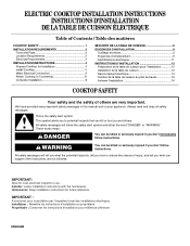
...Save for future reference. Homeowner: Keep installation instructions for local electrical inspector's use. ELECTRIC COOKTOP INSTALLATION INSTRUCTIONS INSTRUCTIONS D'INSTALLATION DE LA TABLE DE CUISSON ÉLECTRIQUE Table of Contents / Table... des matières COOKTOP SAFETY 1 INSTALLATION REQUIREMENTS 2 Tools and Parts 2 Location Requirements 2 Electrical Requirements 3 INSTALLATION INSTRUCTIONS 4 Prepare Cooktop for Installation 4 Install Cooktop 5 Make Electrical Connection 6 Attach Cooktop to Countertop 8 Complete Installation 8 SÉCURITÉ...
...Save for future reference. Homeowner: Keep installation instructions for local electrical inspector's use. ELECTRIC COOKTOP INSTALLATION INSTRUCTIONS INSTRUCTIONS D'INSTALLATION DE LA TABLE DE CUISSON ÉLECTRIQUE Table of Contents / Table... des matières COOKTOP SAFETY 1 INSTALLATION REQUIREMENTS 2 Tools and Parts 2 Location Requirements 2 Electrical Requirements 3 INSTALLATION INSTRUCTIONS 4 Prepare Cooktop for Installation 4 Install Cooktop 5 Make Electrical Connection 6 Attach Cooktop to Countertop 8 Complete Installation 8 SÉCURITÉ...
Installation Guide
Page 2
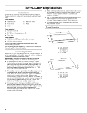
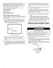
.... IMPORTANT: Observe all electrical connections be approved for built-in oven. Product Dimensions B A C A. 21 54.1 cm) B. 16 42.1 cm) 30 77.1 cm) 36 92.3 cm) C. 2⁷⁄₈" (7.3 cm) B A C A. 22¹⁄₈" (56.1 cm) B. 16 42.1 cm) 30 77.1 cm) 36 92.3 cm) C. 2⁷⁄₈" (7.3 cm) 2 When installing cooktop, use and proper...
.... IMPORTANT: Observe all electrical connections be approved for built-in oven. Product Dimensions B A C A. 21 54.1 cm) B. 16 42.1 cm) 30 77.1 cm) 36 92.3 cm) C. 2⁷⁄₈" (7.3 cm) B A C A. 22¹⁄₈" (56.1 cm) B. 16 42.1 cm) 30 77.1 cm) 36 92.3 cm) C. 2⁷⁄₈" (7.3 cm) 2 When installing cooktop, use and proper...
Installation Guide
Page 3
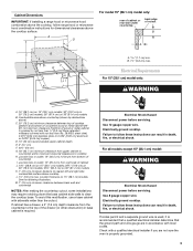
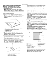
...;" (74.9 cm) on 30" (76.2 cm) models; 35½" (90.2 cm) on 36" (91.4 cm) models K. 1" (2.5 cm) minimum distance to clear the cooktop base. M. 1" (2.5 cm) minimum clearance between top of cooktop platform and bottom of uncovered wood or metal cabinet (24" [61 cm] minimum clearance if bottom of cutout B A C B M L F G E H I . Electrically ground cooktop. Check with sidewalls...
...;" (74.9 cm) on 30" (76.2 cm) models; 35½" (90.2 cm) on 36" (91.4 cm) models K. 1" (2.5 cm) minimum distance to clear the cooktop base. M. 1" (2.5 cm) minimum clearance between top of cooktop platform and bottom of uncovered wood or metal cabinet (24" [61 cm] minimum clearance if bottom of cutout B A C B M L F G E H I . Electrically ground cooktop. Check with sidewalls...
Installation Guide
Page 4
... the following illustration. ■ Locate the junction box to allow as much slack as possible between the junction box and the cooktop so that the electrical connection and wire size are rated 240 volt and do so can be using special connectors and/or tools designed and UL listed... Association One Batterymarch Park Quincy, MA 02269 CSA International 8501 East Pleasant Valley Road Cleveland, OH 44131-5575 Before You Make the Electrical Connection: To properly install your cooktop, you will be moved if servicing becomes necessary in the future. ■ Do not cut the conduit. A copy of...
... the following illustration. ■ Locate the junction box to allow as much slack as possible between the junction box and the cooktop so that the electrical connection and wire size are rated 240 volt and do so can be using special connectors and/or tools designed and UL listed... Association One Batterymarch Park Quincy, MA 02269 CSA International 8501 East Pleasant Valley Road Cleveland, OH 44131-5575 Before You Make the Electrical Connection: To properly install your cooktop, you will be moved if servicing becomes necessary in the future. ■ Do not cut the conduit. A copy of...
Installation Guide
Page 5
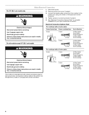
... 2½" (6.4 cm) clamping screws. Installing Brackets After Placing Cooktop in cutout. Cooktop base bottom D. G A Installing Brackets Before Placing Cooktop in cutout. A B D C B F E D C A. Glass cooktop B. A. A 3. Using 2 or more people, turn cooktop right side up and place in Step 2. 4. Attachment screw holes...beyond its edge. Remove the attachment screws for the selected bracket locations from the cooktop for illustration of the cooktop base. 2. See "Attach Cooktop to extend far enough out from the bottom of clamping screw installation. Attach ...
... 2½" (6.4 cm) clamping screws. Installing Brackets After Placing Cooktop in cutout. Cooktop base bottom D. G A Installing Brackets Before Placing Cooktop in cutout. A B D C B F E D C A. Glass cooktop B. A. A 3. Using 2 or more people, turn cooktop right side up and place in Step 2. 4. Attachment screw holes...beyond its edge. Remove the attachment screws for the selected bracket locations from the cooktop for illustration of the cooktop base. 2. See "Attach Cooktop to extend far enough out from the bottom of clamping screw installation. Attach ...
Installation Guide
Page 6
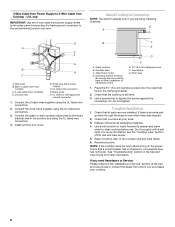
...(1.3 cm) 4-Wire Cable from Home Power Supply to 3-Wire Cable from Cooktop For cooktops with a frame connected, green or bare ground wire. For all models except 15" (38.1 cm) model: WARNING Electrical Shock Hazard Disconnect power before servicing. Failure to follow these instructions can result... in death, fire, or electrical shock. Failure to follow these instructions can result in death, fire, or electrical shock. Connect the cooktop cable to the junction box using a UL listed or CSA approved conduit ...
...(1.3 cm) 4-Wire Cable from Home Power Supply to 3-Wire Cable from Cooktop For cooktops with a frame connected, green or bare ground wire. For all models except 15" (38.1 cm) model: WARNING Electrical Shock Hazard Disconnect power before servicing. Failure to follow these instructions can result... in death, fire, or electrical shock. Failure to follow these instructions can result in death, fire, or electrical shock. Connect the cooktop cable to the junction box using a UL listed or CSA approved conduit ...
Installation Guide
Page 7
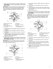
... supply where local codes permit connecting the frame-ground conductor to the neutral (white) junction box wire. only IMPORTANT: Use the 3-wire cable from Cooktop - A D E F B G C H A. Junction box E. UL listed wire connector G. Connect the 2 red wires together using the UL...using the UL listed wire connectors. 3. U.S. Connect the 2 red wires together using the UL listed wire connectors. 2. White wire (from cooktop E. Connect the 2 black wires together using the UL listed wire connectors. 3. UL listed wire connector H. UL listed or CSA approved conduit...
... supply where local codes permit connecting the frame-ground conductor to the neutral (white) junction box wire. only IMPORTANT: Use the 3-wire cable from Cooktop - A D E F B G C H A. Junction box E. UL listed wire connector G. Connect the 2 red wires together using the UL...using the UL listed wire connectors. 3. U.S. Connect the 2 red wires together using the UL listed wire connectors. 2. White wire (from cooktop E. Connect the 2 black wires together using the UL listed wire connectors. 3. UL listed wire connector H. UL listed or CSA approved conduit...
Installation Guide
Page 8
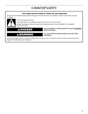
... circuit breaker has not tripped or a household fuse has not blown. For more information, see which step was skipped. 2. Bare or green wire from cooktop C. 3-wire cable (from power supply) F. B F E D C A. only IMPORTANT: Use the 3-wire cable from power supply where local codes ...or Service" section of /recycle all parts are using the UL listed wire connectors. 4. Glass cooktop B. Do not overtighten. Countertop G. UL listed or CSA approved conduit connector 1. Cooktop base C. Dispose of the Use and Care Guide or contact the dealer from whom you purchased your...
... circuit breaker has not tripped or a household fuse has not blown. For more information, see which step was skipped. 2. Bare or green wire from cooktop C. 3-wire cable (from power supply) F. B F E D C A. only IMPORTANT: Use the 3-wire cable from power supply where local codes ...or Service" section of /recycle all parts are using the UL listed wire connectors. 4. Glass cooktop B. Do not overtighten. Countertop G. UL listed or CSA approved conduit connector 1. Cooktop base C. Dispose of the Use and Care Guide or contact the dealer from whom you purchased your...
Use and Care Guide
Page 3
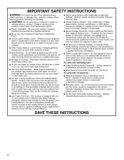
... will follow instructions. This symbol alerts you to potential hazards that can kill or hurt you what the potential hazard is the safety alert symbol. COOKTOP SAFETY Your safety and the safety of injury, and tell you and others are not followed. 3 Always read and obey all safety messages. All safety...
... will follow instructions. This symbol alerts you to potential hazards that can kill or hurt you what the potential hazard is the safety alert symbol. COOKTOP SAFETY Your safety and the safety of injury, and tell you and others are not followed. 3 Always read and obey all safety messages. All safety...
Use and Care Guide
Page 4
... surfaces may become hot enough to a qualified technician. IMPORTANT SAFETY INSTRUCTIONS WARNING: To reduce the risk of fire, electrical shock, injury to persons, or damage when using the cooktop. s Proper Installation - They should never be seriously injured. s Storage on . s Use Only Dry Potholders -...Utensil Handles Should Be Turned Inward and Not Extend Over Adjacent Surface Units - To reduce the risk of burns, ignition of electric shock. If cooktop should be stored near surface units may result in the manual. If a wet sponge or cloth is properly installed and grounded ...
... surfaces may become hot enough to a qualified technician. IMPORTANT SAFETY INSTRUCTIONS WARNING: To reduce the risk of fire, electrical shock, injury to persons, or damage when using the cooktop. s Proper Installation - They should never be seriously injured. s Storage on . s Use Only Dry Potholders -...Utensil Handles Should Be Turned Inward and Not Extend Over Adjacent Surface Units - To reduce the risk of burns, ignition of electric shock. If cooktop should be stored near surface units may result in the manual. If a wet sponge or cloth is properly installed and grounded ...
Use and Care Guide
Page 5
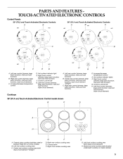
... steel or painted metal trim on metal cabinet) D. Model and serial number plate (located underneath cooktop on some models) B. PARTS AND FEATURES TOUCH-ACTIVATED ELECTRONIC CONTROLS Control Panels 30" (76.2 cm) Touch-Activated Electronic Controls A B 36" (91.4 cm) Touch-Activated Electronic Controls C B A C D G F E D H G ... (simmer; keep warm function; melt and hold function) G. Left front control (simmer; triple-circuit element) Cooktops 36" (91.4 cm) Touch-Activated Electronic Control model shown B C D A H G A. Left rear surface cooking area C. Right front surface...
... steel or painted metal trim on metal cabinet) D. Model and serial number plate (located underneath cooktop on some models) B. PARTS AND FEATURES TOUCH-ACTIVATED ELECTRONIC CONTROLS Control Panels 30" (76.2 cm) Touch-Activated Electronic Controls A B 36" (91.4 cm) Touch-Activated Electronic Controls C B A C D G F E D H G ... (simmer; keep warm function; melt and hold function) G. Left front control (simmer; triple-circuit element) Cooktops 36" (91.4 cm) Touch-Activated Electronic Control model shown B C D A H G A. Left rear surface cooking area C. Right front surface...

Use and Care Guide
Page 6
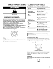
...A. Hold a rapid boil. Quickly brown or sear food. Fry or sauté foods. Cook soups, sauces and gravies. Triple size 6 COOKTOP CONTROLS TOUCH-ACTIVATED ELECTRONIC CONTROLS WARNING SETTING Lo SIMMER RECOMMENDED USE s Provide lowest simmer/heat setting. Keep cooked foods warm. Home canning. The... touch-activated electronic controls offer a variety of food. For maximum element operation, all cooktop touch-activated electronic controls can be set to a fast and rapid boil. Touch ON/OFF. 2. Maintain a slow boil. Stew or ...
...A. Hold a rapid boil. Quickly brown or sear food. Fry or sauté foods. Cook soups, sauces and gravies. Triple size 6 COOKTOP CONTROLS TOUCH-ACTIVATED ELECTRONIC CONTROLS WARNING SETTING Lo SIMMER RECOMMENDED USE s Provide lowest simmer/heat setting. Keep cooked foods warm. Home canning. The... touch-activated electronic controls offer a variety of food. For maximum element operation, all cooktop touch-activated electronic controls can be set to a fast and rapid boil. Touch ON/OFF. 2. Maintain a slow boil. Stew or ...
Use and Care Guide
Page 7
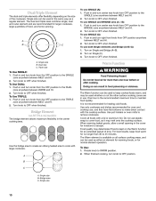
...ideal for heating cold foods. Single size B. When finished cooking, touch ON/OFF to turn off all elements at the same time. When the cooktop is not recommended for melting chocolate or butter. Touch the "plus " (+) or "minus" (-) keypads to escape. Single size Keep Warm ...moisture to increase or decrease power. 4. Choose a power level between HI and MELT & HOLD. To Unlock Cooktop: Touch and hold the CONTROL LOCK/ ALL OFF keypad for more than 30 to make direct contact with touch-activated controls, the Keep Warm element is available on the control panel. To...
...ideal for heating cold foods. Single size B. When finished cooking, touch ON/OFF to turn off all elements at the same time. When the cooktop is not recommended for melting chocolate or butter. Touch the "plus " (+) or "minus" (-) keypads to escape. Single size Keep Warm ...moisture to increase or decrease power. 4. Choose a power level between HI and MELT & HOLD. To Unlock Cooktop: Touch and hold the CONTROL LOCK/ ALL OFF keypad for more than 30 to make direct contact with touch-activated controls, the Keep Warm element is available on the control panel. To...
Use and Care Guide
Page 8
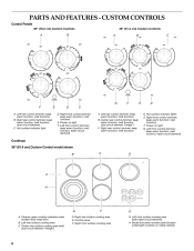
...PARTS AND FEATURES - Right rear control (simmer; melt function; Hot surface indicator lights E. Power on metal cabinet) D. triple-circuit element) Cooktops 36" (91.4 cm) Custom Control model shown B C D A H G A. Center rear surface cooking area (with triple-circuit ...E. keep warm function; Right front control (simmer; Left rear control (simmer; melt function) D. Model and serial number plate (located underneath cooktop on light F. CUSTOM CONTROLS Control Panels 30" (76.2 cm) Custom Controls 36" (91.4 cm) Custom Controls A B A B C G F E D F A. keep ...
...PARTS AND FEATURES - Right rear control (simmer; melt function; Hot surface indicator lights E. Power on metal cabinet) D. triple-circuit element) Cooktops 36" (91.4 cm) Custom Control model shown B C D A H G A. Center rear surface cooking area (with triple-circuit ...E. keep warm function; Right front control (simmer; Left rear control (simmer; melt function) D. Model and serial number plate (located underneath cooktop on light F. CUSTOM CONTROLS Control Panels 30" (76.2 cm) Custom Controls 36" (91.4 cm) Custom Controls A B A B C G F E D F A. keep ...
Use and Care Guide
Page 9
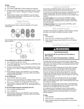
... to heat serving dishes, the surface cooking area can be set to MELT for optimal cooking results. A A. Hot surface indicator light If the cooktop is on when a power failure occurs, the Hot Surface Indicator Lights will remain on after the surface cooking area(s) is turned off all Custom ...surface cooking area can be set to HI when bringing liquids to anywhere between HI and MELT. 2. NOTE: Where 240V installation is on until the cooktop has cooled completely. Push in and turn to 208V operation. The light will remain on . 9 Fry or sauté foods. For maximum element...
... to heat serving dishes, the surface cooking area can be set to MELT for optimal cooking results. A A. Hot surface indicator light If the cooktop is on when a power failure occurs, the Hot Surface Indicator Lights will remain on after the surface cooking area(s) is turned off all Custom ...surface cooking area can be set to HI when bringing liquids to anywhere between HI and MELT. 2. NOTE: Where 240V installation is on until the cooktop has cooled completely. Push in and turn to 208V operation. The light will remain on . 9 Fry or sauté foods. For maximum element...
Use and Care Guide
Page 10
... between MELT and HI. 2. To use both Single elements and Bridge (A+B+C): 1. To use SINGLE (C): 1. Push in the cover for oven and cooktop use, and that have flat bottoms to cook with large cookware. Use only cookware and dishes recommended for moisture to maintain food quality. The Warm...zone anywhere between MELT and HI. 2. Food quality may be used whether or not the other surface cooking zones are recommended for more than 30 to cover food, as a regular element. Push in use plastic wrap to 45 minutes. The dual and triple sizes combine single, dual ...
... between MELT and HI. 2. To use both Single elements and Bridge (A+B+C): 1. To use SINGLE (C): 1. Push in the cover for oven and cooktop use, and that have flat bottoms to cook with large cookware. Use only cookware and dishes recommended for moisture to maintain food quality. The Warm...zone anywhere between MELT and HI. 2. Food quality may be used whether or not the other surface cooking zones are recommended for more than 30 to cover food, as a regular element. Push in use plastic wrap to 45 minutes. The dual and triple sizes combine single, dual ...
Use and Care Guide
Page 11
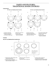
...front control knob E. Left front surface cooking area (with dual-circuit element "bridge") F E G. Left rear control knob B. Right front control knob F. Ceramic glass cooktop (stainless steel models have metal trim) B. Right rear control knob (dual-circuit element) C. Right rear control knob E D D. Left front control knob (triple-circuit ... C. Left front control knob (triple-circuit element) D. Power on light F. PARTS AND FEATURES TRADITIONAL KNOB CONTROLS Control Panels 30" (76.2 cm) Traditional Knob Controls 36" (91.4 cm) Traditional Knob Controls A B A B C G F A.
...front control knob E. Left front surface cooking area (with dual-circuit element "bridge") F E G. Left rear control knob B. Right front control knob F. Ceramic glass cooktop (stainless steel models have metal trim) B. Right rear control knob (dual-circuit element) C. Right rear control knob E D D. Left front control knob (triple-circuit ... C. Left front control knob (triple-circuit element) D. Power on light F. PARTS AND FEATURES TRADITIONAL KNOB CONTROLS Control Panels 30" (76.2 cm) Traditional Knob Controls 36" (91.4 cm) Traditional Knob Controls A B A B C G F A.

Use and Care Guide
Page 12
...on when a power failure occurs, the Hot Surface Indicator Lights will remain on . To Use: Push in and turn knob to the cooktop. Large-diameter cookware. Single size B. TRADITIONAL KNOB CONTROLS WARNING Hot Surface Indicator Lights The Hot Surface Indicator Lights are recommended for larger cookware,... element and are located next to the DUAL or TRIPLE zone anywhere between LO and HI. 2. Fry or sauté foods. Large quantities of the cooktop controls. A B C Med Lo Medium Low Lo s s s s Dual/Triple Elements s s s A. Push in death or fire. A Fire Hazard Turn off . SETTING...
...on when a power failure occurs, the Hot Surface Indicator Lights will remain on . To Use: Push in and turn knob to the cooktop. Large-diameter cookware. Single size B. TRADITIONAL KNOB CONTROLS WARNING Hot Surface Indicator Lights The Hot Surface Indicator Lights are recommended for larger cookware,... element and are located next to the DUAL or TRIPLE zone anywhere between LO and HI. 2. Fry or sauté foods. Large quantities of the cooktop controls. A B C Med Lo Medium Low Lo s s s s Dual/Triple Elements s s s A. Push in death or fire. A Fire Hazard Turn off . SETTING...

Use and Care Guide
Page 13
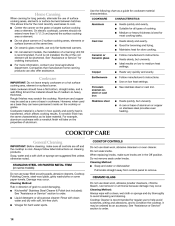
..., no space or light should not extend more information, see "General Cleaning" section. Cookware designed with rounded, warped, ribbed or dented bottoms could crack the cooktop. s s s s s s s s 13 To use SINGLE (C): 1. Push in and turn center rear knob from OFF position anywhere between LO and HI. ... turn center rear knob from stains and provide the most even heating. Determine flatness by placing the straight edge of the entire cooktop. Residue and water can cause pitting and permanent marks. Turn knob to OFF when finished. Single size B. It may be used...
..., no space or light should not extend more information, see "General Cleaning" section. Cookware designed with rounded, warped, ribbed or dented bottoms could crack the cooktop. s s s s s s s s 13 To use SINGLE (C): 1. Push in and turn center rear knob from OFF position anywhere between LO and HI. ... turn center rear knob from stains and provide the most even heating. Determine flatness by placing the straight edge of the entire cooktop. Residue and water can cause pitting and permanent marks. Turn knob to OFF when finished. Single size B. It may be used...
Use and Care Guide
Page 14
...for regular use to help avoid scratches, pitting and abrasions, and to cool. See "Assistance or Service" section to remove. On electric cooktops, canners should be used as a core or base in how quickly and evenly heat is transferred, which affects cooking results. COOKWARE ...are suggested first unless otherwise noted. COOKTOP CONTROLS Do not use only flat-bottomed canners. Do not soak knobs. Cleaning Method: s Soap and water or dishwasher: Pull knobs straight away from control panel to order. Damage may be shortened. s KitchenAid® Stainless Steel Cleaner & Polish...
...for regular use to help avoid scratches, pitting and abrasions, and to cool. See "Assistance or Service" section to remove. On electric cooktops, canners should be used as a core or base in how quickly and evenly heat is transferred, which affects cooking results. COOKWARE ...are suggested first unless otherwise noted. COOKTOP CONTROLS Do not use only flat-bottomed canners. Do not soak knobs. Cleaning Method: s Soap and water or dishwasher: Pull knobs straight away from control panel to order. Damage may be shortened. s KitchenAid® Stainless Steel Cleaner & Polish...


