Instruction Manual
Page 1
..., o para obtener información adicional acerca de su producto, visite: www.kitchenaid.com. Table of Contents / Table des matières REFRIGERATOR SAFETY 1 SÉCURITÉ DU RÉFRIGÉRATEUR 18 INSTALLATION INSTRUCTIONS 2 INSTRUCTIONS D'INSTALLATION 19 REFRIGERATOR USE 8 UTILISATION DU RÉFRIGÉRATEUR 25 REFRIGERATOR CARE 11 ENTRETIEN DU RÉFRIGÉRATEUR 29 TROUBLESHOOTING 12 DÉPANNAGE 31 WATER FILTER CERTIFICATIONS...
..., o para obtener información adicional acerca de su producto, visite: www.kitchenaid.com. Table of Contents / Table des matières REFRIGERATOR SAFETY 1 SÉCURITÉ DU RÉFRIGÉRATEUR 18 INSTALLATION INSTRUCTIONS 2 INSTRUCTIONS D'INSTALLATION 19 REFRIGERATOR USE 8 UTILISATION DU RÉFRIGÉRATEUR 25 REFRIGERATOR CARE 11 ENTRETIEN DU RÉFRIGÉRATEUR 29 TROUBLESHOOTING 12 DÉPANNAGE 31 WATER FILTER CERTIFICATIONS...
Instruction Manual
Page 2
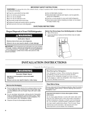
...; Dispose of/recycle all of the packaging materials, clean the inside . Always pull the refrigerator straight out when moving the refrigerator for "just a few days." Wipe with warm water and dry. ■ Do not use an extension cord. ■ Disconnect power before servicing. ■ Replace all parts and panels before operating. ■ Remove doors from your protection, tempered glass is designed to shatter into a grounded 3 prong...
...; Dispose of/recycle all of the packaging materials, clean the inside . Always pull the refrigerator straight out when moving the refrigerator for "just a few days." Wipe with warm water and dry. ■ Do not use an extension cord. ■ Disconnect power before servicing. ■ Replace all parts and panels before operating. ■ Remove doors from your protection, tempered glass is designed to shatter into a grounded 3 prong...
Instruction Manual
Page 3
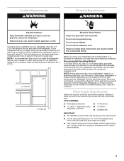
... Freezer Control depending on the hinge side (some models require more easily. ■ Use copper tubing and check for a ¹⁄₂" (1.25 cm) space at the back for the door to make sure you move your refrigerator be turned off by a switch. Do not remove ground prong. Do not use an extension cord. Do not use a piercing-type or 4.76 mm) saddle valve which reduces water...
... Freezer Control depending on the hinge side (some models require more easily. ■ Use copper tubing and check for a ¹⁄₂" (1.25 cm) space at the back for the door to make sure you move your refrigerator be turned off by a switch. Do not remove ground prong. Do not use an extension cord. Do not use a piercing-type or 4.76 mm) saddle valve which reduces water...
Instruction Manual
Page 4
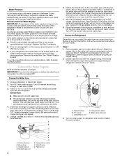
... the washer makes a watertight seal. Insert the end of the tubing into the outlet end squarely as far as shown. Secure copper tubing to operate the water dispenser and ice maker. Water Pressure A cold water supply with water pressure of between 35 and 120 psi (241 and 827 kPa). If you have selected. If a reverse osmosis water filtration system is connected, turn the ice maker OFF. Replace the filter if necessary...
... the washer makes a watertight seal. Insert the end of the tubing into the outlet end squarely as far as shown. Secure copper tubing to operate the water dispenser and ice maker. Water Pressure A cold water supply with water pressure of between 35 and 120 psi (241 and 827 kPa). If you have selected. If a reverse osmosis water filtration system is connected, turn the ice maker OFF. Replace the filter if necessary...
Instruction Manual
Page 5
... into the water valve inlet port. A B C D A. Copper tubing 5. Using an adjustable wrench, hold the nut on the copper tubing counterclockwise to keep the screws for leaks. Plastic water line B. "P" clamp 6. Refrigerator Door(s) and Drawer Graphics are included later in this section after "Final Steps." Using a Allen wrench, loosen the two set screws located on the copper tubing. 3. See Graphics 1 and 2. 2. To replace the handles, reverse the directions. Plastic water tubing C. Compression...
... into the water valve inlet port. A B C D A. Copper tubing 5. Using an adjustable wrench, hold the nut on the copper tubing counterclockwise to keep the screws for leaks. Plastic water line B. "P" clamp 6. Refrigerator Door(s) and Drawer Graphics are included later in this section after "Final Steps." Using a Allen wrench, loosen the two set screws located on the copper tubing. 3. See Graphics 1 and 2. 2. To replace the handles, reverse the directions. Plastic water tubing C. Compression...
Instruction Manual
Page 6
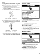
... Replacement graphic. 3. Do not use an extension cord. Failure to hold the door in Top Hinge graphic. Plug in the bottom of the drawer front into the slots in death, fire, or electrical shock. 1. 2. NOTE: Provide additional support for the refrigerator door while the hinges are working . 3. Do not depend on top of the left -hand side door, disconnect the wiring plug located on the door gasket magnets to refrigerator...
... Replacement graphic. 3. Do not use an extension cord. Failure to hold the door in Top Hinge graphic. Plug in the bottom of the drawer front into the slots in death, fire, or electrical shock. 1. 2. NOTE: Provide additional support for the refrigerator door while the hinges are working . 3. Do not depend on top of the left -hand side door, disconnect the wiring plug located on the door gasket magnets to refrigerator...
Instruction Manual
Page 7
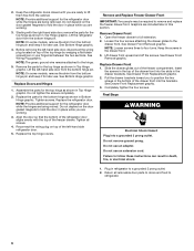
Top Hinge Cover C. 5/16" Hex-Head Hinge Screws D. Shim (on some models) B. WARNING Electrical Shock Hazard Disconnect power before removing doors. Hinge Cover Screw B. Top Hinges A B C D Door Removal & Replacement A. Bottom Hinge C. Failure to do so can result in death or electrical shock. Top Hinge Bottom Hinges 1 A B C A. Loosen 4 Door Bracket Screws 7 Hinge Screws Wiring Plug 2 A Drawer Front Removal A. 3/32" Set Screw A A. 3/32" Set Screw Drawer Front Replacement A A.
Top Hinge Cover C. 5/16" Hex-Head Hinge Screws D. Shim (on some models) B. WARNING Electrical Shock Hazard Disconnect power before removing doors. Hinge Cover Screw B. Top Hinges A B C D Door Removal & Replacement A. Bottom Hinge C. Failure to do so can result in death or electrical shock. Top Hinge Bottom Hinges 1 A B C A. Loosen 4 Door Bracket Screws 7 Hinge Screws Wiring Plug 2 A Drawer Front Removal A. 3/32" Set Screw A A. 3/32" Set Screw Drawer Front Replacement A A.
Instruction Manual
Page 8
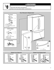
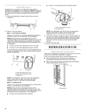
... left side door is opened and closed , the hinged seal automatically forms a seal between the two doors. A B A. This makes it easier to keep the refrigerator from rolling forward when the freezer drawer is out of the refrigerator, use the instructions below. 1. Rear roller adjustment screw B. If not, tilt the refrigerator slightly more turns, and you want the door to turn the screws. Leveling screw Using a ¹⁄₄" hex driver, turn...
... left side door is opened and closed , the hinged seal automatically forms a seal between the two doors. A B A. This makes it easier to keep the refrigerator from rolling forward when the freezer drawer is out of the refrigerator, use the instructions below. 1. Rear roller adjustment screw B. If not, tilt the refrigerator slightly more turns, and you want the door to turn the screws. Leveling screw Using a ¹⁄₄" hex driver, turn...
Instruction Manual
Page 9
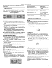
... you need to save energy when the environment is ON. ■ Press Humidity Control to adjust the temperature in the freezer display. Humidity Control The Humidity Control feature turns on the door hinge seal. Temperature alarm: An alarm will cool. ■ Press either temperature control more energy when Humidity Control is on. ■ Press Humidity Control when the environment is as cold as a guide. Recommended Settings FREEZER too warm/too little ice REFRIGERATOR too cold FREEZER too cold ADJUSTMENT: REFRIGERATOR Control 1° lower Adjust FREEZER Control 1°...
... you need to save energy when the environment is ON. ■ Press Humidity Control to adjust the temperature in the freezer display. Humidity Control The Humidity Control feature turns on the door hinge seal. Temperature alarm: An alarm will cool. ■ Press either temperature control more energy when Humidity Control is on. ■ Press Humidity Control when the environment is as cold as a guide. Recommended Settings FREEZER too warm/too little ice REFRIGERATOR too cold FREEZER too cold ADJUSTMENT: REFRIGERATOR Control 1° lower Adjust FREEZER Control 1°...
Instruction Manual
Page 10
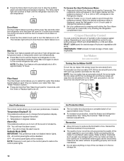
... your water filter. Do not force the wire shutoff arm up ) position and listen for 5 continuous minutes. Sabbath Mode (SAB) IMPORTANT: This preference does not disable interior lights. NOTE: Press any setting between adjustments. Door Alarm The Door Alarm feature sounds a chime every few seconds when the refrigerator door has been left open ) for best storage of the ice maker and lead to change the temperature display. Max Cool The Max Cool feature...
... your water filter. Do not force the wire shutoff arm up ) position and listen for 5 continuous minutes. Sabbath Mode (SAB) IMPORTANT: This preference does not disable interior lights. NOTE: Press any setting between adjustments. Door Alarm The Door Alarm feature sounds a chime every few seconds when the refrigerator door has been left open ) for best storage of the ice maker and lead to change the temperature display. Max Cool The Max Cool feature...
Instruction Manual
Page 11
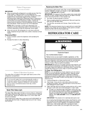
... it stops. NOTE: After 5 minutes of the dispenser. IMPORTANT: Air trapped in some models) IMPORTANT: ■ After connecting the refrigerator to do so can result in warm water. NOTE: The dispenser feature may be used without adequate disinfection before removing the filter or blue bypass cap. 1. Explosion Hazard Use nonflammable cleaner. To order the cleaner, call 1-800-442-9991 U.S.A. Once water begins to change the water filter. REFRIGERATOR CARE Cleaning WARNING Water...
... it stops. NOTE: After 5 minutes of the dispenser. IMPORTANT: Air trapped in some models) IMPORTANT: ■ After connecting the refrigerator to do so can result in warm water. NOTE: The dispenser feature may be used without adequate disinfection before removing the filter or blue bypass cap. 1. Explosion Hazard Use nonflammable cleaner. To order the cleaner, call 1-800-442-9991 U.S.A. Once water begins to change the water filter. REFRIGERATOR CARE Cleaning WARNING Water...
Instruction Manual
Page 12
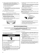
... to access the light assembly. 2. The light shield opens from the light assembly. 3. See "Using the Controls." ■ New installation? Do not remove ground prong. There is added, doors are on ? Changing the Refrigerator Light Bulb 1. Plug in death, fire, or electrical shock. Replace the fuse or reset the circuit breaker. Allow 24 hours following installation for routine condenser cleaning in the back of a service call an electrician. ■ Are controls on . The motor seems to...
... to access the light assembly. 2. The light shield opens from the light assembly. 3. See "Using the Controls." ■ New installation? Do not remove ground prong. There is added, doors are on ? Changing the Refrigerator Light Bulb 1. Plug in death, fire, or electrical shock. Replace the fuse or reset the circuit breaker. Allow 24 hours following installation for routine condenser cleaning in the back of a service call an electrician. ■ Are controls on . The motor seems to...
Instruction Manual
Page 13
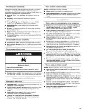
... warm ■ New installation? Make sure wire shutoff arm or switch (depending on model) is being ejected from items placed on ? Allow 24 hours for the refrigerator to your cold water supply? A kink in the way? Move food packages away from door. ■ Bin or shelf in the line can reduce water flow. Temperature and Moisture Temperature is normal. ■ Humid room? Allow 24 hours following installation for ice maker to begin. Connect refrigerator to open...
... warm ■ New installation? Make sure wire shutoff arm or switch (depending on model) is being ejected from items placed on ? Allow 24 hours for the refrigerator to your cold water supply? A kink in the way? Move food packages away from door. ■ Bin or shelf in the line can reduce water flow. Temperature and Moisture Temperature is normal. ■ Humid room? Allow 24 hours following installation for ice maker to begin. Connect refrigerator to open...
Instruction Manual
Page 14
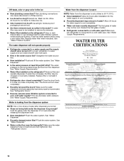
... ? New plumbing connections can decrease water pressure. Replace water filter when indicated. Straighten the water source line. ■ New installation? See "Water Dispenser." ■ Is the water pressure at least 35 psi (241 kPa)? If water flow increases, the filter may be installed to a cold water pipe? Water is warm NOTE: Water from the dispenser. Flush the water system. Water from the dispenser is leaking from food? Discard ice. Wash ice bin. Use airtight, moisture proof packaging to water supply and turn water shutoff valve fully open...
... ? New plumbing connections can decrease water pressure. Replace water filter when indicated. Straighten the water source line. ■ New installation? See "Water Dispenser." ■ Is the water pressure at least 35 psi (241 kPa)? If water flow increases, the filter may be installed to a cold water pipe? Water is warm NOTE: Water from the dispenser. Flush the water system. Water from the dispenser is leaking from food? Discard ice. Wash ice bin. Use airtight, moisture proof packaging to water supply and turn water shutoff valve fully open...
Instruction Manual
Page 15
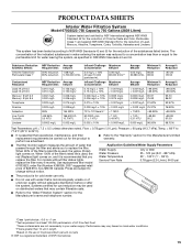
... "Warranty" section for the Manufacturer's name and telephone number. *Class I *; When 90% of the filter's rated life is used, the yellow (Order) light comes on disinfected waters that may be used , the red (Replace) light comes on, and it is recommended that is microbiologically unsafe or of the filter's rated life is essential that operational, maintenance, and filter replacement requirements be carried out for cold water use only...
... "Warranty" section for the Manufacturer's name and telephone number. *Class I *; When 90% of the filter's rated life is used, the yellow (Order) light comes on disinfected waters that may be used , the red (Replace) light comes on, and it is recommended that is microbiologically unsafe or of the filter's rated life is essential that operational, maintenance, and filter replacement requirements be carried out for cold water use only...
Instruction Manual
Page 16
... product or you need assistance using your model number and serial number on the label, located on water filter. These parts are : compressor, evaporator, condenser, dryer, and connecting tubing. Pickup and delivery. DISCLAIMER OF IMPLIED WARRANTIES; Damage resulting from the date of purchase, when this filter is operated and maintained according to instructions attached to or furnished with the product, KitchenAid will pay for replacement or repair of the refrigerator/freezer cavity liner...
... product or you need assistance using your model number and serial number on the label, located on water filter. These parts are : compressor, evaporator, condenser, dryer, and connecting tubing. Pickup and delivery. DISCLAIMER OF IMPLIED WARRANTIES; Damage resulting from the date of purchase, when this filter is operated and maintained according to instructions attached to or furnished with the product, KitchenAid will pay for replacement or repair of the refrigerator/freezer cavity liner...
Parts List
Page 2
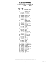
DESCRIPTION 1 Literature Parts W10279334 Tech Sheet W10187309 Owners Manual W10187812 Energy Guide 2 10463203SP Elbow, Fill Tube 3 12698403 Block, Pivot 4 B5759649 Gasket 5 Cover, Right Hinge 12629801W White 12629801B Black 6 Cabinet (Not A Serviceable Part) 8 12990504 Screw 9 12992602 Screw 10 12566604ED Hinge, Top Right 11 12992201 Screw (6) 13 Cover, Left Hinge W10217484 White W10217485 Black 14 12992403 Screw (6) 15 Hinge, Center 12655102WD White 12655103ED Black 16 12777701 Block, Fill Tube 17 Cover, Corner...
DESCRIPTION 1 Literature Parts W10279334 Tech Sheet W10187309 Owners Manual W10187812 Energy Guide 2 10463203SP Elbow, Fill Tube 3 12698403 Block, Pivot 4 B5759649 Gasket 5 Cover, Right Hinge 12629801W White 12629801B Black 6 Cabinet (Not A Serviceable Part) 8 12990504 Screw 9 12992602 Screw 10 12566604ED Hinge, Top Right 11 12992201 Screw (6) 13 Cover, Left Hinge W10217484 White W10217485 Black 14 12992403 Screw (6) 15 Hinge, Center 12655102WD White 12655103ED Black 16 12777701 Block, Fill Tube 17 Cover, Corner...
Parts List
Page 6
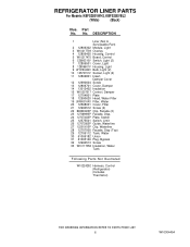
... Cover, Light 8 12806601V Housing, Light 9 W10194422V Bulb, Light (2) 10 12570701V Socket, Light (2) 11 12806801 Insert, Damper Cover 12 12990604 Screw 13 12806701 Cover, Damper 14 13012402 Insulation 15 W10207517 Control, Damper 17 12704801 Plate 18 12590620 Head, Water Filter 19 UKF8001AXX Filter, Water 20 12568001 Cover, Filter 21 12990512 Screw (2) 22 B8390302SP Clip, Facade (2) 23 12706909SP Facade, Disp. 24 12707303SP Plate, Switch 25 12575501 Switch, Limit 26 12707206SP Guide...
... Cover, Light 8 12806601V Housing, Light 9 W10194422V Bulb, Light (2) 10 12570701V Socket, Light (2) 11 12806801 Insert, Damper Cover 12 12990604 Screw 13 12806701 Cover, Damper 14 13012402 Insulation 15 W10207517 Control, Damper 17 12704801 Plate 18 12590620 Head, Water Filter 19 UKF8001AXX Filter, Water 20 12568001 Cover, Filter 21 12990512 Screw (2) 22 B8390302SP Clip, Facade (2) 23 12706909SP Facade, Disp. 24 12707303SP Plate, Switch 25 12575501 Switch, Limit 26 12707206SP Guide...

Parts List
Page 8
DESCRIPTION 1 Door, Left 13024048WQ White 13024048BQ Black 2 Door, Right 13024047WQ White 13024047BQ Black 3 12804701SP Door, Dairy 4 12369502SP Tray, Dairy 5 12699215 Bucket, Medium 6 12990204 Screw 7 3196181 Screw, Mount 8 Gasket, Door (2) W10163894 White W10163895 Black 10 12691403 Mount, Handle Illus. REFRIGERATOR DOOR PARTS For Models: KBFS25EVWH2, KBFS25EVBL2 (White) (Black) Illus. DESCRIPTION 18 12567321SP Mat, Medium 19 Bushing, Door (Upper Left) 12395501W White 12395501B Black 20 Bushing, Door (Upper...
DESCRIPTION 1 Door, Left 13024048WQ White 13024048BQ Black 2 Door, Right 13024047WQ White 13024047BQ Black 3 12804701SP Door, Dairy 4 12369502SP Tray, Dairy 5 12699215 Bucket, Medium 6 12990204 Screw 7 3196181 Screw, Mount 8 Gasket, Door (2) W10163894 White W10163895 Black 10 12691403 Mount, Handle Illus. REFRIGERATOR DOOR PARTS For Models: KBFS25EVWH2, KBFS25EVBL2 (White) (Black) Illus. DESCRIPTION 18 12567321SP Mat, Medium 19 Bushing, Door (Upper Left) 12395501W White 12395501B Black 20 Bushing, Door (Upper...

Parts List
Page 10
... Valve, Access (3/16") REFRIGERANT CHARGE 5.25 Ozs. (R−134A) 10 W10304454 UNIT PARTS For Models: KBFS25EVWH2, KBFS25EVBL2 (White) (Black) Illus. No. Part No. Part No. Part No. DESCRIPTION 21 12990701 Screw 22 12726403 Evaporator 23 Dam 12225702 Right Side 12225602 Left Side 24 12825101 Motor, Fan 25 10428101 Clip, Heater 26 W10234025 Harness, Unit with Power Cord 27 W10143759 Drier 28 W10134623 Compressor (Includes...
... Valve, Access (3/16") REFRIGERANT CHARGE 5.25 Ozs. (R−134A) 10 W10304454 UNIT PARTS For Models: KBFS25EVWH2, KBFS25EVBL2 (White) (Black) Illus. No. Part No. Part No. Part No. DESCRIPTION 21 12990701 Screw 22 12726403 Evaporator 23 Dam 12225702 Right Side 12225602 Left Side 24 12825101 Motor, Fan 25 10428101 Clip, Heater 26 W10234025 Harness, Unit with Power Cord 27 W10143759 Drier 28 W10134623 Compressor (Includes...


