
User Manual
Page 1
144/440 MHz FM DUAL BANDER TM-V7A 144/430 MHz FM DUAL BANDER TM-V7A 144/430 MHz FM DUAL BANDER TM-V7E INSTRUCTION MANUAL KENWOOD CORPORATION © B62-1503-00 (K,E,M) 09 08 07 06 05 04 03 02 01 00
144/440 MHz FM DUAL BANDER TM-V7A 144/430 MHz FM DUAL BANDER TM-V7A 144/430 MHz FM DUAL BANDER TM-V7E INSTRUCTION MANUAL KENWOOD CORPORATION © B62-1503-00 (K,E,M) 09 08 07 06 05 04 03 02 01 00
User Manual
Page 2
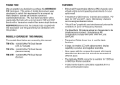
... positive and negative reversible. • Save space with a transceiver smaller than some single banders. KENWOOD believes that 's simple to VHF and UHF bands with the compact front panel which easily detaches ... use the basic functions. • A large, dot matrix LCD with this manual. MODELS COVERED BY THIS MANUAL The models listed below are grateful you decided to satisfy the requirement for VHF and... can be appreciated by this product. TM-V7A: 144/440 MHz FM Dual Bander (U.S.A./ Canada) TM-V7A: 144/430 MHz FM Dual Bander (General market) TM-V7E: 144/430 MHz FM Dual Bander ...
... positive and negative reversible. • Save space with a transceiver smaller than some single banders. KENWOOD believes that 's simple to VHF and UHF bands with the compact front panel which easily detaches ... use the basic functions. • A large, dot matrix LCD with this manual. MODELS COVERED BY THIS MANUAL The models listed below are grateful you decided to satisfy the requirement for VHF and... can be appreciated by this product. TM-V7A: 144/440 MHz FM Dual Bander (U.S.A./ Canada) TM-V7A: 144/430 MHz FM Dual Bander (General market) TM-V7E: 144/430 MHz FM Dual Bander ...
User Manual
Page 3
... If an abnormal odor or smoke is detected coming from that the interference will function normally. Changes or modifications to this manual or by KENWOOD documentation. • Do not expose the transceiver to long periods of direct sunlight nor place the transceiver close to heating ...appliances. • Do not place the transceiver in a particular installation. These limits are expressly approved in transceiver malfunction. Contact a KENWOOD service station or your transceiver while driving because it is simply too dangerous. • Be aware of local laws pertaining to the ...
... If an abnormal odor or smoke is detected coming from that the interference will function normally. Changes or modifications to this manual or by KENWOOD documentation. • Do not expose the transceiver to long periods of direct sunlight nor place the transceiver close to heating ...appliances. • Do not place the transceiver in a particular installation. These limits are expressly approved in transceiver malfunction. Contact a KENWOOD service station or your transceiver while driving because it is simply too dangerous. • Be aware of local laws pertaining to the ...
User Manual
Page 4
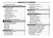
CONTENTS SUPPLIED ACCESSORIES 1 CONVENTIONS FOLLOWED IN THIS MANUAL ....... 1 1 PREPERATION FOR MOBILE AND FIXED STATION OPERATION MOBILE INSTALLATION 2 Installation Example 2 Installation Steps 2 DC POWER CABLE CONNECTION 3 Mobile Operation 3 Fixed Station Operation 4 Replacing Fuses 5 ANTENNA ...
CONTENTS SUPPLIED ACCESSORIES 1 CONVENTIONS FOLLOWED IN THIS MANUAL ....... 1 1 PREPERATION FOR MOBILE AND FIXED STATION OPERATION MOBILE INSTALLATION 2 Installation Example 2 Installation Steps 2 DC POWER CABLE CONNECTION 3 Mobile Operation 3 Fixed Station Operation 4 Replacing Fuses 5 ANTENNA ...

User Manual
Page 7
...) J19-1526-XX 1 Microphone hanger screws 2 N46-3010-XX 2 (U.S.A./ Canada only) Warranty card (U.S.A./ Canada/ Europe only) - 1 Instruction manual B62-1503-XX 1 1 The MC-53DM and MC-45 microphones are also sold as optional accessories {page 83}. 2 Attach the microphone hanger... (1 s), [KEY]. Press and hold [F] down, then press KEY. 1 Microphone hanger Microphone hanger screw CONVENTIONS FOLLOWED IN THIS MANUAL The writing conventions described below have been followed to do Press and release KEY. What to simplify instructions and avoid unnecessary repetition. Press...
...) J19-1526-XX 1 Microphone hanger screws 2 N46-3010-XX 2 (U.S.A./ Canada only) Warranty card (U.S.A./ Canada/ Europe only) - 1 Instruction manual B62-1503-XX 1 1 The MC-53DM and MC-45 microphones are also sold as optional accessories {page 83}. 2 Attach the microphone hanger... (1 s), [KEY]. Press and hold [F] down, then press KEY. 1 Microphone hanger Microphone hanger screw CONVENTIONS FOLLOWED IN THIS MANUAL The writing conventions described below have been followed to do Press and release KEY. What to simplify instructions and avoid unnecessary repetition. Press...

User Manual
Page 13
... to receive. 1 2 3 4 5 6 7 8 9 10 11 12 13 14 15 16 17 18 19 20 21 7 YOUR FIRST QSO If you tend to discard instruction manuals along with opening a brand new transceiver. rt y e wweww MC-53DM t Press and hold Mic [PTT], then speak in your most comfortable operating chair with this... manual and your first QSO right away. The time spent will get you on the air in your favorite drink for a while, settle back in a normal...
... to receive. 1 2 3 4 5 6 7 8 9 10 11 12 13 14 15 16 17 18 19 20 21 7 YOUR FIRST QSO If you tend to discard instruction manuals along with opening a brand new transceiver. rt y e wweww MC-53DM t Press and hold Mic [PTT], then speak in your most comfortable operating chair with this... manual and your first QSO right away. The time spent will get you on the air in your favorite drink for a while, settle back in a normal...

User Manual
Page 16
... {page 46}. 19 20 21 10 e MR button Selects the Memory Recall mode {page 31}. Also starts or stops Memory Scan {page 44}. In this manual. 3 4 CALL 5 6 7 8 9 10 q CALL button 11 Recalls the Call channel {page 33}.
... {page 46}. 19 20 21 10 e MR button Selects the Memory Recall mode {page 31}. Also starts or stops Memory Scan {page 44}. In this manual. 3 4 CALL 5 6 7 8 9 10 q CALL button 11 Recalls the Call channel {page 33}.

User Manual
Page 21
... exit Guide mode, press [MNU] again. The following table lists the function indexes that you will often use a function and you do not have this manual with you, you need not worry. Page Function Index Ref. TRANSCEIVER GUIDE When you cannot recall how to use .
... exit Guide mode, press [MNU] again. The following table lists the function indexes that you will often use a function and you do not have this manual with you, you need not worry. Page Function Index Ref. TRANSCEIVER GUIDE When you cannot recall how to use .
User Manual
Page 25
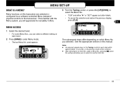
... No. MENU SET-UP 1 WHAT IS A MENU? 3 Turn the Tuning control, or press Mic [UP]/[DWN], to select the Menu No. 2 Many functions on this manual. 11 Note: ◆ As required, operate keys or the Tuning control in this transceiver are selected or configured via a software-controlled Menu instead of •...
... No. MENU SET-UP 1 WHAT IS A MENU? 3 Turn the Tuning control, or press Mic [UP]/[DWN], to select the Menu No. 2 Many functions on this manual. 11 Note: ◆ As required, operate keys or the Tuning control in this transceiver are selected or configured via a software-controlled Menu instead of •...

User Manual
Page 27
... minutes 12 1 DTSS/ Page Code Transmit Delay 350 ms/ 550 ms OFF 61 7 10 minutes 61 350 ms 52,56 8 2 Auto Page Cancel Auto (ON)/ manual (OFF) Manual 57 9 3 Page Answer Back ON/ OFF OFF 57 10 (U.S.A./ Canada only) 13 1 S-meter Squelch ON/ OFF OFF 2 S-meter Squelch Hang Time 125 ms/ 250...
... minutes 12 1 DTSS/ Page Code Transmit Delay 350 ms/ 550 ms OFF 61 7 10 minutes 61 350 ms 52,56 8 2 Auto Page Cancel Auto (ON)/ manual (OFF) Manual 57 9 3 Page Answer Back ON/ OFF OFF 57 10 (U.S.A./ Canada only) 13 1 S-meter Squelch ON/ OFF OFF 2 S-meter Squelch Hang Time 125 ms/ 250...

User Manual
Page 33
... to a simplex frequency to continue the contact and free up the repeater. REVERSE FUNCTION When used while monitoring a repeater, the Reverse function allows you to manually check the signal strength of the 1 signal you are receiving from the repeater. Note: ◆ If pressing [REV] places the transmit frequency outside the allowable...
... to a simplex frequency to continue the contact and free up the repeater. REVERSE FUNCTION When used while monitoring a repeater, the Reverse function allows you to manually check the signal strength of the 1 signal you are receiving from the repeater. Note: ◆ If pressing [REV] places the transmit frequency outside the allowable...

User Manual
Page 63
... code each time you 1 received the Page call. CALL VOL SQL 3 Press [s], then select Item No. 2 (PAG Cancel). CALL VOL SQL 2 1 4 Press [SET] to toggle Manual (default) or Auto. 5 Press [MNU] again to exit Menu mode. 16 Note: Once the transceiver sends an answer back signal, it 17 automatically switches Answer...
... code each time you 1 received the Page call. CALL VOL SQL 3 Press [s], then select Item No. 2 (PAG Cancel). CALL VOL SQL 2 1 4 Press [SET] to toggle Manual (default) or Auto. 5 Press [MNU] again to exit Menu mode. 16 Note: Once the transceiver sends an answer back signal, it 17 automatically switches Answer...

User Manual
Page 68
.... 5 • "A.B.C." when in urban areas when the RX band is restored 2 seconds after a signal is received on which band you to reply to a caller without 3 manually selecting the correct band. 4 Press [F], [MNU] to exit Menu mode. Switching back to Single-band mode 14 deactivates A.B.C. This problem is often apparent in Single...
.... 5 • "A.B.C." when in urban areas when the RX band is restored 2 seconds after a signal is received on which band you to reply to a caller without 3 manually selecting the correct band. 4 Press [F], [MNU] to exit Menu mode. Switching back to Single-band mode 14 deactivates A.B.C. This problem is often apparent in Single...

User Manual
Page 70
... any VHF frequency. Outside this range, the default is FM. However, either mode can also receive in the range of the transceiver can be selected manually on the display. PROGRAMMABLE VFO 1 If you want, you can set limits for the minimum and 2 maximum frequencies that are selectable using the Tuning control...
... any VHF frequency. Outside this range, the default is FM. However, either mode can also receive in the range of the transceiver can be selected manually on the display. PROGRAMMABLE VFO 1 If you want, you can set limits for the minimum and 2 maximum frequencies that are selectable using the Tuning control...
User Manual
Page 94
Black ➞ ( - ). 13 14 15 and pressing the (POWER) switch. This is defective. 4 Note: When 2 frequencies are received in this 3 instruction manual, before assuming your transceiver is not a defect. 5 VHF/UHF mode: (UHF receive frequency - 45.05 MHz) x 2 - (VHF receive frequency + 38.85 MHz) x 4 = 38.85 MHz ...
Black ➞ ( - ). 13 14 15 and pressing the (POWER) switch. This is defective. 4 Note: When 2 frequencies are received in this 3 instruction manual, before assuming your transceiver is not a defect. 5 VHF/UHF mode: (UHF receive frequency - 45.05 MHz) x 2 - (VHF receive frequency + 38.85 MHz) x 4 = 38.85 MHz ...

User Manual
Page 96
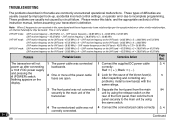
... to do Full Reset {page 35}. Push the switch momentarily to do Partial Reset or press it for 1 second or longer to the TNC instruction manual. 10 3 Reorient or relocate the antenna. parameter on packet. 12 4 The TX delay of 16 ambient factors. 17 18 19 Viewed with other stations. 9 target...
... to do Full Reset {page 35}. Push the switch momentarily to do Partial Reset or press it for 1 second or longer to the TNC instruction manual. 10 3 Reorient or relocate the antenna. parameter on packet. 12 4 The TX delay of 16 ambient factors. 17 18 19 Viewed with other stations. 9 target...