
User Manual
Page 5
...-MH BATTERY PACK (OTHER THAN TH-K2AT K2/ M2, TH-K4AT M2 6 CONNECTING TO A CIGARETTE LIGHTER SOCKET 8 CONNECTING TO A REGULATED POWER SUPPLY 9 YOUR FIRST QSO 10 FIRST QSO 10 GETTING ACQUAINTED 12 KEYS AND CONTROLS 12 DISPLAY 14 BASIC OPERATION 17 Switching the Power ON/OFF 17 Adjusting the Volume 17 Adjusting the Squelch 18 Transmitting 19 Selecting an Output Power 19 Selecting a Frequency 20 VFO Mode 20 MHz Mode 20 Direct Frequency Entry (TH...
...-MH BATTERY PACK (OTHER THAN TH-K2AT K2/ M2, TH-K4AT M2 6 CONNECTING TO A CIGARETTE LIGHTER SOCKET 8 CONNECTING TO A REGULATED POWER SUPPLY 9 YOUR FIRST QSO 10 FIRST QSO 10 GETTING ACQUAINTED 12 KEYS AND CONTROLS 12 DISPLAY 14 BASIC OPERATION 17 Switching the Power ON/OFF 17 Adjusting the Volume 17 Adjusting the Squelch 18 Transmitting 19 Selecting an Output Power 19 Selecting a Frequency 20 VFO Mode 20 MHz Mode 20 Direct Frequency Entry (TH...

User Manual
Page 6
... A MEMORY CHANNEL 47 NAMING A MEMORY CHANNEL 48 MEMORY CHANNEL TRANSFER 50 Memory a VFO Transfer 50 Channel a Channel Transfer 50 CALL CHANNEL 53 Recalling the Call Channel 53 Reprogramming the Call Channel 54 WEATHER ALERT (TH-K2AT K/ K2 ONLY 55 Programming the Weather Radio Frequency 55 ii MENU SETUP 24 WHAT IS A MENU 24 MENU ACCESS 24 MENU FUNCTION LIST 26 ALPHABETICAL FUNCTION LIST 29 OPERATING THROUGH REPEATERS 31 OFFSET PROGRAMMING FLOW 32 Programming an...
... A MEMORY CHANNEL 47 NAMING A MEMORY CHANNEL 48 MEMORY CHANNEL TRANSFER 50 Memory a VFO Transfer 50 Channel a Channel Transfer 50 CALL CHANNEL 53 Recalling the Call Channel 53 Reprogramming the Call Channel 54 WEATHER ALERT (TH-K2AT K/ K2 ONLY 55 Programming the Weather Radio Frequency 55 ii MENU SETUP 24 WHAT IS A MENU 24 MENU ACCESS 24 MENU FUNCTION LIST 26 ALPHABETICAL FUNCTION LIST 29 OPERATING THROUGH REPEATERS 31 OFFSET PROGRAMMING FLOW 32 Programming an...

User Manual
Page 8
... 95 TX POWER 95 VOX (VOICE-OPERATED TRANSMISSION 96 VOX Gain 97 VOX Delay Time 99 VOX on Busy 100 OPTIONAL ACCESSORIES 101 INTERFACING TO PERIPHERALS 104 SP/MIC JACK 104 SP/MIC 104 PC 105 Using the PG-4Y PC Interface Cable 106 Using the MCP-1A Software 107 TROUBLESHOOTING 108 GENERAL INFORMATION 108 Service 108 Service Note 109 Cleaning 110 BACKUP BATTERY 110 iv
... 95 TX POWER 95 VOX (VOICE-OPERATED TRANSMISSION 96 VOX Gain 97 VOX Delay Time 99 VOX on Busy 100 OPTIONAL ACCESSORIES 101 INTERFACING TO PERIPHERALS 104 SP/MIC JACK 104 SP/MIC 104 PC 105 Using the PG-4Y PC Interface Cable 106 Using the MCP-1A Software 107 TROUBLESHOOTING 108 GENERAL INFORMATION 108 Service 108 Service Note 109 Cleaning 110 BACKUP BATTERY 110 iv
User Manual
Page 10
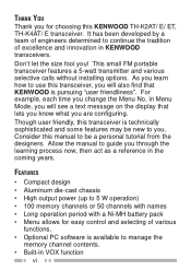
... die-cast chassis • High output power (up to 5 W operation) • 100 memory channels or 50 channels with names • Long operation period with a Ni-MH battery pack • Menu allows for choosing this KENWOOD TH-K2AT/ E/ ET, TH-K4AT/ E transceiver. For example, each time you ! Allow the manual to manage the memory channel contents. • Built-in Menu Mode, you will also find that lets...
... die-cast chassis • High output power (up to 5 W operation) • 100 memory channels or 50 channels with names • Long operation period with a Ni-MH battery pack • Menu allows for choosing this KENWOOD TH-K2AT/ E/ ET, TH-K4AT/ E transceiver. For example, each time you ! Allow the manual to manage the memory channel contents. • Built-in Menu Mode, you will also find that lets...

User Manual
Page 22
... 24V 12V PG-2W Note: x Do not use the optional PG-3J Cigarette Lighter cable. To connect with an external 24 V power source via a DC-DC converter, only use the PG-2W to connect a vehicle battery (12 V) directly. x If the input voltage exceeds approximately 16.5 V, warning beeps sound and "DC ERR" appears. 8 While you operate the transceiver, it charges the PB-43N...
... 24V 12V PG-2W Note: x Do not use the optional PG-3J Cigarette Lighter cable. To connect with an external 24 V power source via a DC-DC converter, only use the PG-2W to connect a vehicle battery (12 V) directly. x If the input voltage exceeds approximately 16.5 V, warning beeps sound and "DC ERR" appears. 8 While you operate the transceiver, it charges the PB-43N...

User Manual
Page 23
... appropriate regulated DC power supply, use an optional PG-2W DC cable. 1 Confirm that the power of the transceiver. Fuses (4 A) 3 Connect the barrel plug on the DC cable to the DC IN jack of both the transceiver and the DC power supply is connected with the DC IN jack, the transceiver automatically initiates charging the PB-43N Ni-MH battery pack. the red lead to the...
... appropriate regulated DC power supply, use an optional PG-2W DC cable. 1 Confirm that the power of the transceiver. Fuses (4 A) 3 Connect the barrel plug on the DC cable to the DC IN jack of both the transceiver and the DC power supply is connected with the DC IN jack, the transceiver automatically initiates charging the PB-43N Ni-MH battery pack. the red lead to the...
User Manual
Page 40
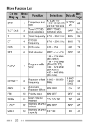
...5 DCS code 023 ~ 754 023 74 SFT P.VFO OFFSET1 ARO2 PRI SCAN L.OUT M.CH 6 Shift direction OFF/ +/ -/ -7.6 OFF 32 136 ~ 174 MHz (TH-K2AT) 144 ~ 146 MHz 7 Programmable (TH-K2E/ ET) VFO 400 ~ 470 MHz 93 (TH-K4AT) 430 ~ 440 MHz (TH-K4E) 8 Repeater offset 0.000 ~ 69.950 frequency MHz 0.600...Priority scan ON/ OFF OFF 66 11 Scan resume method TO/ CO/ SE 12 Memory lockout channel ON/ OFF 13 Memory capacity channel 50/ 100 TO 68 OFF 67 50 41 26 Function 1 Frequency step size 2 Tone/ CTCSS/ DCS selection Selections Default Ref. MENU FUNCTION LIST On the Display ...
...5 DCS code 023 ~ 754 023 74 SFT P.VFO OFFSET1 ARO2 PRI SCAN L.OUT M.CH 6 Shift direction OFF/ +/ -/ -7.6 OFF 32 136 ~ 174 MHz (TH-K2AT) 144 ~ 146 MHz 7 Programmable (TH-K2E/ ET) VFO 400 ~ 470 MHz 93 (TH-K4AT) 430 ~ 440 MHz (TH-K4E) 8 Repeater offset 0.000 ~ 69.950 frequency MHz 0.600...Priority scan ON/ OFF OFF 66 11 Scan resume method TO/ CO/ SE 12 Memory lockout channel ON/ OFF 13 Memory capacity channel 50/ 100 TO 68 OFF 67 50 41 26 Function 1 Frequency step size 2 Tone/ CTCSS/ DCS selection Selections Default Ref. MENU FUNCTION LIST On the Display ...
User Manual
Page 47
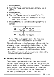
... frequency pair, change the offset direction. 1 Press [MENU]. 2 Turn the Tuning control to select Menu No. 6 (SFT). 3 Press [MENU]. 4 Turn the Tuning control to select "+" or "-". • To program a -7.6 MHz offset (TH-K4E only), select "-7.6" instead. 5 Press [MENU] to store the setting or [PTT] to cancel. • "+" or "-" (or " ") appears above the frequency, indicating which offset direction is 600 kHz (all TH-K2 models); The default offset frequency on the 70 cm band...
... frequency pair, change the offset direction. 1 Press [MENU]. 2 Turn the Tuning control to select Menu No. 6 (SFT). 3 Press [MENU]. 4 Turn the Tuning control to select "+" or "-". • To program a -7.6 MHz offset (TH-K4E only), select "-7.6" instead. 5 Press [MENU] to store the setting or [PTT] to cancel. • "+" or "-" (or " ") appears above the frequency, indicating which offset direction is 600 kHz (all TH-K2 models); The default offset frequency on the 70 cm band...

User Manual
Page 55
... Memory Name function (default). To change the memory channel capacity: 1 Press [MENU]. 2 Turn the Tuning control to select Menu No. 13 (M.CH). 3 Press [MENU]. 4 Turn the Tuning control to cancel. 41 appears. 6 Press [MENU] to reprogram that data every time. MEMORY CHANNELS In memory channels, you can quickly recall a programmed channel through simple operation. NUMBER OF MEMORY CHANNELS The transceiver must be configured to either 100 memory channels without using the Memory Name...
... Memory Name function (default). To change the memory channel capacity: 1 Press [MENU]. 2 Turn the Tuning control to select Menu No. 13 (M.CH). 3 Press [MENU]. 4 Turn the Tuning control to cancel. 41 appears. 6 Press [MENU] to reprogram that data every time. MEMORY CHANNELS In memory channels, you can quickly recall a programmed channel through simple operation. NUMBER OF MEMORY CHANNELS The transceiver must be configured to either 100 memory channels without using the Memory Name...

User Manual
Page 59
... operate on those repeaters without programming the offset frequency and direction. 1 Store the desired reception frequency and related data by following the procedure given for simplex or standard repeater frequencies {page 44}. 2 Turn the Tuning control to select the desired transmission frequency. 3 Press [F], [MR]. 4 Turn the Tuning control to select the memory channel you recall an odd-split memory channel, "+" and "-" appear on the display...
... operate on those repeaters without programming the offset frequency and direction. 1 Store the desired reception frequency and related data by following the procedure given for simplex or standard repeater frequencies {page 44}. 2 Turn the Tuning control to select the desired transmission frequency. 3 Press [F], [MR]. 4 Turn the Tuning control to select the memory channel you recall an odd-split memory channel, "+" and "-" appear on the display...

User Manual
Page 71
...]+[ ] (POWER). • The transceiver displays the memory channel number in the background: 1 Perform step 1 ~ 4 above. 2 Press [VFO] or [MR] and turn the Tuning control to select your desired memory channel number. 57 x If the transceiver is transmitting or receiving a signal on the LCD. 3 When the Weather Alert tone is broadcasted, the transceiver automatically switches to the Weather Radio frequency. 4 To exit the Weather Alert Mode, press [MENU], select Menu...
...]+[ ] (POWER). • The transceiver displays the memory channel number in the background: 1 Perform step 1 ~ 4 above. 2 Press [VFO] or [MR] and turn the Tuning control to select your desired memory channel number. 57 x If the transceiver is transmitting or receiving a signal on the LCD. 3 When the Weather Alert tone is broadcasted, the transceiver automatically switches to the Weather Radio frequency. 4 To exit the Weather Alert Mode, press [MENU], select Menu...

User Manual
Page 75
... scanning. Program Scan monitors the range between the start frequency. 3 Press [F], [MR] then turn the Tuning control to one of the memory channel pairs (L0/U0 ~ L2/U2). Note: x While scanning, you have stored in Menu No. 7 (P.VFO) {page 93}. Release [MONI/SQL] to start and end frequencies. Program Scan You can change the scan frequency direction by turning the Tuning control. x If you press [MONI/SQL], Band Scan temporarily pauses. There are 3 memory channel pairs...
... scanning. Program Scan monitors the range between the start frequency. 3 Press [F], [MR] then turn the Tuning control to one of the memory channel pairs (L0/U0 ~ L2/U2). Note: x While scanning, you have stored in Menu No. 7 (P.VFO) {page 93}. Release [MONI/SQL] to start and end frequencies. Program Scan You can change the scan frequency direction by turning the Tuning control. x If you press [MONI/SQL], Band Scan temporarily pauses. There are 3 memory channel pairs...

User Manual
Page 80
...). 2 Press [MENU] and turn the Tuning control to select "ON". 3 Press [MENU] to store the setting. • "PRI" appears. 4 Press any key other than [PTT], [LAMP], and [MONI/SQL] to exit Menu Mode. • The transceiver checks for a signal on the Priority Channel every 3 seconds. • When the transceiver detects a signal on a Priority Channel with a CTCSS or DCS code programmed, the Priority Channel is recalled...
...). 2 Press [MENU] and turn the Tuning control to select "ON". 3 Press [MENU] to store the setting. • "PRI" appears. 4 Press any key other than [PTT], [LAMP], and [MONI/SQL] to exit Menu Mode. • The transceiver checks for a signal on the Priority Channel every 3 seconds. • When the transceiver detects a signal on a Priority Channel with a CTCSS or DCS code programmed, the Priority Channel is recalled...

User Manual
Page 87
.... DCS DCS is activated. 4 Press any key other than [MENU], [MONI/SQL], and [LAMP] to exit the Menu Mode. You can select a DCS code from among the 104 DCS codes listed in the table on the display, indicating that represents a 3-digit octal number. Note: You cannot use the DCS function and CTCSS/ Tone functions simultaneously. Switching the DCS function ON after having...
.... DCS DCS is activated. 4 Press any key other than [MENU], [MONI/SQL], and [LAMP] to exit the Menu Mode. You can select a DCS code from among the 104 DCS codes listed in the table on the display, indicating that represents a 3-digit octal number. Note: You cannot use the DCS function and CTCSS/ Tone functions simultaneously. Switching the DCS function ON after having...

User Manual
Page 104
... before connecting the optional speaker microphone. x While Menu No. 31 (PC) is "ON" {page 107} or the Lock function is ON, you must move the switch to the OFF position to alternate VFO and Memory Recall Mode. 2 Tuning control (Up or Down) can also be programmed. 3 The light stays ON until you cannot program PF keys. MONI/ SQL MONI/ SQL Squelch adjustment PTT1 PTT Change power setting MENU MENU...
... before connecting the optional speaker microphone. x While Menu No. 31 (PC) is "ON" {page 107} or the Lock function is ON, you must move the switch to the OFF position to alternate VFO and Memory Recall Mode. 2 Tuning control (Up or Down) can also be programmed. 3 The light stays ON until you cannot program PF keys. MONI/ SQL MONI/ SQL Squelch adjustment PTT1 PTT Change power setting MENU MENU...

User Manual
Page 131
... connection is open fuse and replace the fuse. Replace the cable. • The power supply fuse is 8 bad. Most keys and the Tuning • Transceiver Lock function is defective. Please review these tables and the appropriate section(s) of difficulties are usually not caused by improper hook-up, accidental incorrect control settings, or operator error due to incomplete programming. Press [PTT]+[MR]+[ ] (POWER) to turn OFF Transceiver Lock. • The transceiver is 2, 6 display...
... connection is open fuse and replace the fuse. Replace the cable. • The power supply fuse is 8 bad. Most keys and the Tuning • Transceiver Lock function is defective. Please review these tables and the appropriate section(s) of difficulties are usually not caused by improper hook-up, accidental incorrect control settings, or operator error due to incomplete programming. Press [PTT]+[MR]+[ ] (POWER) to turn OFF Transceiver Lock. • The transceiver is 2, 6 display...

User Manual
Page 132
... • The current frequency step 87 desired frequency using the Tuning control. The receiving sound volume • The receiving station may be 91 is weak even if the signal is plugged into the SP/MIC jack, you to be selected. Turning the VOL control • The selective call function. Select an appropriate frequency step size in PC Mode. 107 Microphone is strong. remote control) through the Speaker/ Microphone. 118 size does not allow you...
... • The current frequency step 87 desired frequency using the Tuning control. The receiving sound volume • The receiving station may be 91 is weak even if the signal is plugged into the SP/MIC jack, you to be selected. Turning the VOL control • The selective call function. Select an appropriate frequency step size in PC Mode. 107 Microphone is strong. remote control) through the Speaker/ Microphone. 118 size does not allow you...

User Manual
Page 136
SPECIFICATIONS General Market code Number of memory channels Antenna impedance (Connector type) Operating Voltage DC IN jack Battery terminal Grounding method Transmit with H, 13.8 V (DC IN) Current Transmit with H, 7.2 V (PB-43N) Transmit with M, 7.2 V (PB-43N) Transmit with L, 7.2 V (PB-43N) 122 TH-K2AT K, K2 M, M2 100 (50) + 9 special function memories 100 (50) + 8 special function memories 50Ω (SMA) DC 12.0 ~ 16.0 V (13.8 V nominal) DC 6.0 ~ 9.0 V (7.2 V nominal) Negative ground 1.8 A or less 2.0 A or less 1.5 A or less 0.8 A or less
SPECIFICATIONS General Market code Number of memory channels Antenna impedance (Connector type) Operating Voltage DC IN jack Battery terminal Grounding method Transmit with H, 13.8 V (DC IN) Current Transmit with H, 7.2 V (PB-43N) Transmit with M, 7.2 V (PB-43N) Transmit with L, 7.2 V (PB-43N) 122 TH-K2AT K, K2 M, M2 100 (50) + 9 special function memories 100 (50) + 8 special function memories 50Ω (SMA) DC 12.0 ~ 16.0 V (13.8 V nominal) DC 6.0 ~ 9.0 V (7.2 V nominal) Negative ground 1.8 A or less 2.0 A or less 1.5 A or less 0.8 A or less
User Manual
Page 144
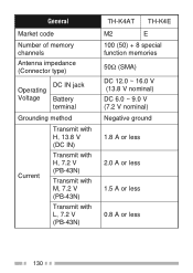
General Market code Number of memory channels Antenna impedance (Connector type) Operating Voltage DC IN jack Battery terminal Grounding method Transmit with H, 13.8 V (DC IN) Current Transmit with H, 7.2 V (PB-43N) Transmit with M, 7.2 V (PB-43N) Transmit with L, 7.2 V (PB-43N) TH-K4AT TH-K4E M2 E 100 (50) + 8 special function memories 50Ω (SMA) DC 12.0 ~ 16.0 V (13.8 V nominal) DC 6.0 ~ 9.0 V (7.2 V nominal) Negative ground 1.8 A or less 2.0 A or less 1.5 A or less 0.8 A or less 130
General Market code Number of memory channels Antenna impedance (Connector type) Operating Voltage DC IN jack Battery terminal Grounding method Transmit with H, 13.8 V (DC IN) Current Transmit with H, 7.2 V (PB-43N) Transmit with M, 7.2 V (PB-43N) Transmit with L, 7.2 V (PB-43N) TH-K4AT TH-K4E M2 E 100 (50) + 8 special function memories 50Ω (SMA) DC 12.0 ~ 16.0 V (13.8 V nominal) DC 6.0 ~ 9.0 V (7.2 V nominal) Negative ground 1.8 A or less 2.0 A or less 1.5 A or less 0.8 A or less 130

User Manual
Page 152
... Channel 54 Reset Full 112 VFO 113 RESET (Menu No. 99 114 Reverse Function 38 S SAV (Menu No. 16 84 Scan All-Channel 63 Band 60 Call 64 Carrier-Operated Mode 68 Seek Mode 68 Time-Operated Mode 68 SCAN (Menu No. 11 68 SFT (Menu No. 6 32 Simplex Storing, Frequencies or Standard 44 SPD (Menu No. 33 80 Specifications 122 Squelch, Adjusting 18 Supplied Accessories vii SP/MIC 12, 89, 104 STP (Menu No. 1 86 Switching Power...
... Channel 54 Reset Full 112 VFO 113 RESET (Menu No. 99 114 Reverse Function 38 S SAV (Menu No. 16 84 Scan All-Channel 63 Band 60 Call 64 Carrier-Operated Mode 68 Seek Mode 68 Time-Operated Mode 68 SCAN (Menu No. 11 68 SFT (Menu No. 6 32 Simplex Storing, Frequencies or Standard 44 SPD (Menu No. 33 80 Specifications 122 Squelch, Adjusting 18 Supplied Accessories vii SP/MIC 12, 89, 104 STP (Menu No. 1 86 Switching Power...


