
User Manual
Page 2
... memory channels programmable with separate receive and transmit frequencies as well as simplex frequencies, and other persons who are covered by this KENWOOD FM transceiver. MICROPHONEFCEOATNUTRREOS L 1 We are grateful you may assign a name such as the display to permit easy operation in Continuous Tone Coded Squelch System (CTCSS) rejects unwanted calls from other various data. • Allows each memory channel to...
... memory channels programmable with separate receive and transmit frequencies as well as simplex frequencies, and other persons who are covered by this KENWOOD FM transceiver. MICROPHONEFCEOATNUTRREOS L 1 We are grateful you may assign a name such as the display to permit easy operation in Continuous Tone Coded Squelch System (CTCSS) rejects unwanted calls from other various data. • Allows each memory channel to...
User Manual
Page 3
... modify this transceiver unless instructed by KENWOOD documentation. 4 • When using a regulated power supply, connect the specified DC cable (option) to radio communications. The transceiver may be determined by one or more of our commitment to collect and recycle Ni-Cd batteries after their operating life has expired. Contact a 13 KENWOOD service station or your area, call (toll free) 1-800-8-BATTERY (1-800-822-8837). This...
... modify this transceiver unless instructed by KENWOOD documentation. 4 • When using a regulated power supply, connect the specified DC cable (option) to radio communications. The transceiver may be determined by one or more of our commitment to collect and recycle Ni-Cd batteries after their operating life has expired. Contact a 13 KENWOOD service station or your area, call (toll free) 1-800-8-BATTERY (1-800-822-8837). This...
User Manual
Page 4
CONTENTS 1 SUPPLIED ACCESSORIES 1 CONVENTIONS FOLLOWED IN THIS MANUAL .... 1 2 CHAPTER q PREPARATION CHAPTER t MENU SET-UP WHAT IS A MENU 10 MENU ACCESS 10 3 BATTERY OPERATING TIME 2 INSTALLING THE NiCd BATTERY PACK 2 4 INSTALLING ALKALINE BATTERIES 3 5 INSTALLING THE ANTENNA 4 ATTACHING THE HAND STRAP 4 6 INSTALLING THE BELT HOOK 4 7 CHAPTER w FIRST QSO CHAPTER e GETTING ACQUAINTED 8 ORIENTATION 6 9 BASIC TRANSCEIVER MODES 6 DISPLAY 7 10 CHAPTER r OPERATING BASICS 11 SWITCHING POWER ON/OFF 8 12 ADJUSTING VOLUME 8 ADJUSTING SQUELCH 8 13 SELECTING A BAND 9 14...
CONTENTS 1 SUPPLIED ACCESSORIES 1 CONVENTIONS FOLLOWED IN THIS MANUAL .... 1 2 CHAPTER q PREPARATION CHAPTER t MENU SET-UP WHAT IS A MENU 10 MENU ACCESS 10 3 BATTERY OPERATING TIME 2 INSTALLING THE NiCd BATTERY PACK 2 4 INSTALLING ALKALINE BATTERIES 3 5 INSTALLING THE ANTENNA 4 ATTACHING THE HAND STRAP 4 6 INSTALLING THE BELT HOOK 4 7 CHAPTER w FIRST QSO CHAPTER e GETTING ACQUAINTED 8 ORIENTATION 6 9 BASIC TRANSCEIVER MODES 6 DISPLAY 7 10 CHAPTER r OPERATING BASICS 11 SWITCHING POWER ON/OFF 8 12 ADJUSTING VOLUME 8 ADJUSTING SQUELCH 8 13 SELECTING A BAND 9 14...
User Manual
Page 6
... Channel Number Entry 40 4 CHANGING FREQUENCY STEP SIZE 40 CHAPTER !2 MICROPHONE CONTROL 5 CHAPTER !3 MAINTENANCE 6 GENERAL INFORMATION 42 SERVICE 42 7 SERVICE NOTE 42 8 CLEANING 42 CHARGING THE NiCd BATTERY PACK 43 9 TROUBLESHOOTING 44 10 CHAPTER !4 OPTIONAL ACCESSORIES CHAPTER !5 EQUIPMENT INSTALLATION AND 11 CONNECTION 12 CONNECTING AN EXTERNAL POWER SOURCE 47 13 Using a Regulated Power Supply 47 Using a Cigarette Lighter Socket 47 14 CONNECTING EQUIPMENT FOR REMOTE CONTROL 48 15 iv CONNECTING OTHER EXTERNAL EQUIPMENT 48 SPECIFICATIONS QUICK REFERENCE GUIDE...
... Channel Number Entry 40 4 CHANGING FREQUENCY STEP SIZE 40 CHAPTER !2 MICROPHONE CONTROL 5 CHAPTER !3 MAINTENANCE 6 GENERAL INFORMATION 42 SERVICE 42 7 SERVICE NOTE 42 8 CLEANING 42 CHARGING THE NiCd BATTERY PACK 43 9 TROUBLESHOOTING 44 10 CHAPTER !4 OPTIONAL ACCESSORIES CHAPTER !5 EQUIPMENT INSTALLATION AND 11 CONNECTION 12 CONNECTING AN EXTERNAL POWER SOURCE 47 13 Using a Regulated Power Supply 47 Using a Cigarette Lighter Socket 47 14 CONNECTING EQUIPMENT FOR REMOTE CONTROL 48 15 iv CONNECTING OTHER EXTERNAL EQUIPMENT 48 SPECIFICATIONS QUICK REFERENCE GUIDE...

User Manual
Page 12
... Tuning control. Antenna Tuning control VOL control On Air/Busy lamp Display Speaker/ Microphone SP jack MIC jack Keypad DC IN jack Memory Recall mode Press [MR] to "MEMORY CHANNELS" {page 17}. You cannot enter this transceiver. For further information, refer to select. In this mode you stored frequencies and related data. In this mode you can change the operating frequency using the Tuning control, where you can select on this mode unless you program...
... Tuning control. Antenna Tuning control VOL control On Air/Busy lamp Display Speaker/ Microphone SP jack MIC jack Keypad DC IN jack Memory Recall mode Press [MR] to "MEMORY CHANNELS" {page 17}. You cannot enter this transceiver. For further information, refer to select. In this mode you stored frequencies and related data. In this mode you can change the operating frequency using the Tuning control, where you can select on this mode unless you program...
User Manual
Page 13
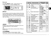
... What You Selected What You Press Ref. Menu mode Press [F], [BAND] to restore 9 10 power default Battery Saver Use Menu No. 4 37 11 Automatic Power Off Transceiver Lock Use Menu No. 5 37 [F] (1 s) 37 12 Memory Channel Lockout Memory channel containing data 1 TH-G71E only [F], [0] - 27 13 18 14 15 7 Displays various alphanumeric information such as an operating frequency or menu selection. In this mode you will see various indicators that show what...
... What You Selected What You Press Ref. Menu mode Press [F], [BAND] to restore 9 10 power default Battery Saver Use Menu No. 4 37 11 Automatic Power Off Transceiver Lock Use Menu No. 5 37 [F] (1 s) 37 12 Memory Channel Lockout Memory channel containing data 1 TH-G71E only [F], [0] - 27 13 18 14 15 7 Displays various alphanumeric information such as an operating frequency or menu selection. In this mode you will see various indicators that show what...

User Manual
Page 15
... select the VHF or UHF band. See "KEYPAD DIRECT ENTRY" {page 40}. Note: If in steps of your signal at the receiving station. 6 • The battery meter shows the current relative battery charge. 7 2 When you cannot select a particular frequency, the frequency step size needs to the microphone, or too loudly, 5 may increase distortion and reduce intelligibility of 1 MHz, press [MHz] first. 1 MHz digit blinks. TRANSMITTING 1 When...
... select the VHF or UHF band. See "KEYPAD DIRECT ENTRY" {page 40}. Note: If in steps of your signal at the receiving station. 6 • The battery meter shows the current relative battery charge. 7 2 When you cannot select a particular frequency, the frequency step size needs to the microphone, or too loudly, 5 may increase distortion and reduce intelligibility of 1 MHz, press [MHz] first. 1 MHz digit blinks. TRANSMITTING 1 When...
User Manual
Page 19
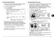
... enter Menu mode. 4 3 Select Menu No. 8 (OFFSET). 5 6 7 4 Press [BAND], then select the appropriate offset frequency. 8 • The selectable range is brought within the band limits by Automatic Repeater Offset. 15 13 TH-G71A/E Simplex + - (VHF) TH-G71A (UHF) TH-G71E (UHF) Simplex + - : Programs -7.6 MHz offset. Note: While using an odd-split memory channel or transmitting, you cannot change the default (-7.6 MHz). 14 Note: After changing the offset frequency, the new offset frequency...
... enter Menu mode. 4 3 Select Menu No. 8 (OFFSET). 5 6 7 4 Press [BAND], then select the appropriate offset frequency. 8 • The selectable range is brought within the band limits by Automatic Repeater Offset. 15 13 TH-G71A/E Simplex + - (VHF) TH-G71A (UHF) TH-G71E (UHF) Simplex + - : Programs -7.6 MHz offset. Note: While using an odd-split memory channel or transmitting, you cannot change the default (-7.6 MHz). 14 Note: After changing the offset frequency, the new offset frequency...

User Manual
Page 24
... appropriate transmit frequency. 3 Press [F]. 4 Within 10 seconds, turn the Tuning control to store two separate frequencies in a single memory channel. Note: ◆ When you may select other related data (CTCSS ON, CTCSS freq., etc.) 8 5 Press [F]. • A memory channel number appears on the display. STORING ODD-SPLIT REPEATER FREQUENCIES Some repeaters use a receive and transmit frequency pair with a non-standard offset. See 4 "KEYPAD DIRECT ENTRY" {page...
... appropriate transmit frequency. 3 Press [F]. 4 Within 10 seconds, turn the Tuning control to store two separate frequencies in a single memory channel. Note: ◆ When you may select other related data (CTCSS ON, CTCSS freq., etc.) 8 5 Press [F]. • A memory channel number appears on the display. STORING ODD-SPLIT REPEATER FREQUENCIES Some repeaters use a receive and transmit frequency pair with a non-standard offset. See 4 "KEYPAD DIRECT ENTRY" {page...

User Manual
Page 25
... display. CLEARING MEMORY CHANNELS 1 Recall the desired memory channel. 1 2 Switch OFF the power to the transceiver. 3 Press [MR]+ POWER ON. 2 • A confirmation message appears. 3 4 2 1 5 4 Press [MR] again. 6 • The contents of the selected memory channel are cleared once you to recall a VHF frequency channel when operating the UHF band. Note: ◆ You can also recall memory channels by directly entering numeric keys. ALL: Recalls all programmed...
... display. CLEARING MEMORY CHANNELS 1 Recall the desired memory channel. 1 2 Switch OFF the power to the transceiver. 3 Press [MR]+ POWER ON. 2 • A confirmation message appears. 3 4 2 1 5 4 Press [MR] again. 6 • The contents of the selected memory channel are cleared once you to recall a VHF frequency channel when operating the UHF band. Note: ◆ You can also recall memory channels by directly entering numeric keys. ALL: Recalls all programmed...
User Manual
Page 29
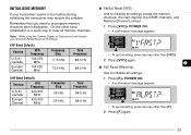
Note: While using the Channel Display or Transceiver Lock function, you need to be malfunctioning, initializing the transceiver may resolve the problem. INITIALIZING MEMORY If your transceiver seems to re-program memory channels after initialization. Remember that you cannot do Partial Reset nor Full Reset. VHF Band Defaults Version U.S.A./ Canada Europe/ General VFO Frequency 144.000 MHz 144.000 MHz Frequency Step ņņņ5 kHz...
Note: While using the Channel Display or Transceiver Lock function, you need to be malfunctioning, initializing the transceiver may resolve the problem. INITIALIZING MEMORY If your transceiver seems to re-program memory channels after initialization. Remember that you cannot do Partial Reset nor Full Reset. VHF Band Defaults Version U.S.A./ Canada Europe/ General VFO Frequency 144.000 MHz 144.000 MHz Frequency Step ņņņ5 kHz...

User Manual
Page 32
... frequency step size {page 40} is used. 2 3 4 5 6 1 Select the desired band. 7 2 Press [VFO] (1 s). 8 • The 1 MHz decimal blinks while scanning is in progress. • Scan starts at the frequency currently displayed. 9 10 3 11 • To reverse the scan direction, turn the Tuning control clockwise (upward scan) or counterclockwise (downward scan). 2 To quit Memory Scan, press any key other than [LAMP], [MONI], and [F]. Note: The squelch must be scanned; otherwise, memory channels...
... frequency step size {page 40} is used. 2 3 4 5 6 1 Select the desired band. 7 2 Press [VFO] (1 s). 8 • The 1 MHz decimal blinks while scanning is in progress. • Scan starts at the frequency currently displayed. 9 10 3 11 • To reverse the scan direction, turn the Tuning control clockwise (upward scan) or counterclockwise (downward scan). 2 To quit Memory Scan, press any key other than [LAMP], [MONI], and [F]. Note: The squelch must be scanned; otherwise, memory channels...

User Manual
Page 33
...; Scan starts at the frequency currently displayed. 11 • To reverse the scan direction, turn the Tuning control clockwise (upward scan) or counterclockwise (downward scan). 12 4 To quit MHz Scan, press any key other than [LAMP], 13 [MONI], and [F]. 14 15 27 The exact upper limit depends on the step size selected. 3 4 5 6 7 1 Press [VFO] to select VFO mode. 8 2 Select the desired band. 9 3 Press [MHz] (1 s) to start...
...; Scan starts at the frequency currently displayed. 11 • To reverse the scan direction, turn the Tuning control clockwise (upward scan) or counterclockwise (downward scan). 12 4 To quit MHz Scan, press any key other than [LAMP], 13 [MONI], and [F]. 14 15 27 The exact upper limit depends on the step size selected. 3 4 5 6 7 1 Press [VFO] to select VFO mode. 8 2 Select the desired band. 9 3 Press [MHz] (1 s) to start...

User Manual
Page 46
... cannot recall a Program Scan channel nor the Priority 15 channel with keypad direct entry. 40 CHANGING FREQUENCY STEP SIZE Choosing the correct step size is displayed with a 5 kHz step size selected, changing to a 12.5 kHz step size corrects the displayed frequency to 144.9875 MHz. The default step size on the 5 keypad. • Enter the digits in order to select your exact receive frequency using the Tuning control. KEYPAD DIRECT ENTRY 1 You can...
... cannot recall a Program Scan channel nor the Priority 15 channel with keypad direct entry. 40 CHANGING FREQUENCY STEP SIZE Choosing the correct step size is displayed with a 5 kHz step size selected, changing to a 12.5 kHz step size corrects the displayed frequency to 144.9875 MHz. The default step size on the 5 keypad. • Enter the digits in order to select your exact receive frequency using the Tuning control. KEYPAD DIRECT ENTRY 1 You can...

User Manual
Page 47
... 4 channel number 0 to assign. • To assign the Up function, rotate the Tuning control 2 clockwise. The assigned default functions are as follows: [1]: Band select [2]: VFO/ Memory Recall mode switch [3]: Call channel recall (TH-G71E: Transmit power select) Note: ◆ Turn OFF the transceiver power before connecting the optional speaker microphone. ◆ If the LOCK switch located on the transceiver 1 that you want to 9. • You can change [CALL...
... 4 channel number 0 to assign. • To assign the Up function, rotate the Tuning control 2 clockwise. The assigned default functions are as follows: [1]: Band select [2]: VFO/ Memory Recall mode switch [3]: Call channel recall (TH-G71E: Transmit power select) Note: ◆ Turn OFF the transceiver power before connecting the optional speaker microphone. ◆ If the LOCK switch located on the transceiver 1 that you want to 9. • You can change [CALL...
User Manual
Page 48
... circuit boards. Please mention the model and serial number of equipment 2 Question or problem you are directly related to the service problem. 10 You may return your transceiver for service to the authorized KENWOOD dealer from whom the transceiver was purchased. ◆ For your station pertaining to the problem 4 Meter readings 5 Other information (Menu setup, mode, frequency, button sequence to the point. Help us help you by a qualified technician who...
... circuit boards. Please mention the model and serial number of equipment 2 Question or problem you are directly related to the service problem. 10 You may return your transceiver for service to the authorized KENWOOD dealer from whom the transceiver was purchased. ◆ For your station pertaining to the problem 4 Meter readings 5 Other information (Menu setup, mode, frequency, button sequence to the point. Help us help you by a qualified technician who...
User Manual
Page 50
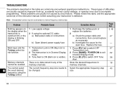
... the 12 cannot be changed. Corrective Action 1 Recharge the battery pack or replace the batteries. 2 a) Check the power cable and connections, then correct/replace as necessary. These problems are usually caused by circuit failure. memory channels. b) Investigate the cause for the open fuse. Replace the fuse. 1 Press [F] (1 s) to switch OFF Transceiver Lock. 2 Press [BAND]+ POWER ON to exit Channel Display mode. 3 Press [F], [7] to incomplete programming. Please review this instruction manual, before assuming your transceiver...
... the 12 cannot be changed. Corrective Action 1 Recharge the battery pack or replace the batteries. 2 a) Check the power cable and connections, then correct/replace as necessary. These problems are usually caused by circuit failure. memory channels. b) Investigate the cause for the open fuse. Replace the fuse. 1 Press [F] (1 s) to switch OFF Transceiver Lock. 2 Press [BAND]+ POWER ON to exit Channel Display mode. 3 Press [F], [7] to incomplete programming. Please review this instruction manual, before assuming your transceiver...
User Manual
Page 51
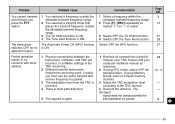
... operation on packet. 8 13 14 15 45 apparent reason. press the PTT 2 You selected a transmit offset that 2 Press [F], [REV] repeatedly so 13 2 switch. Usually, transmit offset. according to the TNC manual. 4 Reorient the antenna. allowable transmit frequency range. If using this 48 manual, your TNC manual and your 7 connects with other stations. strongest signal does not always provide the 12 5 The squelch is 3 Adjust...
... operation on packet. 8 13 14 15 45 apparent reason. press the PTT 2 You selected a transmit offset that 2 Press [F], [REV] repeatedly so 13 2 switch. Usually, transmit offset. according to the TNC manual. 4 Reorient the antenna. allowable transmit frequency range. If using this 48 manual, your TNC manual and your 7 connects with other stations. strongest signal does not always provide the 12 5 The squelch is 3 Adjust...

User Manual
Page 53
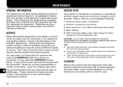
Note: If input voltage exceeds approximately 18 V, warning beeps sound and "DC ERR" appears on the power supply. Connect the black lead of this cable to the negative (-) terminal. 2 Connect the barrel plug on the DC cable to the DC IN jack on the side of the optional PG-2W DC cable to the positive (+) terminal on the display. ■ Using a Regulated Power Supply Note: ◆ Switch OFF...
Note: If input voltage exceeds approximately 18 V, warning beeps sound and "DC ERR" appears on the power supply. Connect the black lead of this cable to the negative (-) terminal. 2 Connect the barrel plug on the DC cable to the DC IN jack on the side of the optional PG-2W DC cable to the positive (+) terminal on the display. ■ Using a Regulated Power Supply Note: ◆ Switch OFF...

User Manual
Page 59
... Channel Contents, Changing 21 Recalling 21 Channel Display Function 22 Connection Cigarette Lighter 47 Regulated Power Supply 47 Continuous Tone Coded Squelch System (CTCSS) Automatic Tone Frequency ID ....... 33 Using 32 Dual Tone Multi-Frequency (DTMF) Functions Confirming Stored Numbers .......... 35 Making Calls 34 Storing Numbers 35 Tone TX Hold 34 Transmitting Stored Numbers ........ 36 Frequency, Selecting 9, 40 Frequency Step Size 40 INDEX Installation Antenna 4 Belt hook 4 Hand strap 4 Keypad Direct Entry Frequency...
... Channel Contents, Changing 21 Recalling 21 Channel Display Function 22 Connection Cigarette Lighter 47 Regulated Power Supply 47 Continuous Tone Coded Squelch System (CTCSS) Automatic Tone Frequency ID ....... 33 Using 32 Dual Tone Multi-Frequency (DTMF) Functions Confirming Stored Numbers .......... 35 Making Calls 34 Storing Numbers 35 Tone TX Hold 34 Transmitting Stored Numbers ........ 36 Frequency, Selecting 9, 40 Frequency Step Size 40 INDEX Installation Antenna 4 Belt hook 4 Hand strap 4 Keypad Direct Entry Frequency...


