
User Manual
Page 2
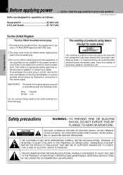
... to the earth terminal of the plug immediately, to avoid a possible shock hazard by inadvertent connection to reach a power point, then obtain an appropriate safety approved extension lead or adapter, or consult your home or the cable is utilizing laser beams that have been classified as follows. The marking of products using lasers (Except for some areas) CLASS...
... to the earth terminal of the plug immediately, to avoid a possible shock hazard by inadvertent connection to reach a power point, then obtain an appropriate safety approved extension lead or adapter, or consult your home or the cable is utilizing laser beams that have been classified as follows. The marking of products using lasers (Except for some areas) CLASS...
User Manual
Page 3
... High grade Micro Component Series 6 About the Instruction Manual 6 Special features 7 System Composition and Installation 8 System connection 9 Antenna connection 9 Connection of audio cord 10 Connection of speakers 12 Connection of system control cord 13 Power Cord Connection 13 Controls and indicators 14 Main Unit 14 Remote control Unit 16 Operation of remote control unit 17 Basic section Hearing sound 18 Basic use Timer (O.T.T 45 Sleep timer 45 Timer programming 46 Knowledge section Basic section Application section Important items 49 Handling of discs and tapes 49...
... High grade Micro Component Series 6 About the Instruction Manual 6 Special features 7 System Composition and Installation 8 System connection 9 Antenna connection 9 Connection of audio cord 10 Connection of speakers 12 Connection of system control cord 13 Power Cord Connection 13 Controls and indicators 14 Main Unit 14 Remote control Unit 16 Operation of remote control unit 17 Basic section Hearing sound 18 Basic use Timer (O.T.T 45 Sleep timer 45 Timer programming 46 Knowledge section Basic section Application section Important items 49 Handling of discs and tapes 49...
User Manual
Page 4
... follow the manufacturer's instructions, and should use a mounting accessory recommended by the manufacturer, or sold with a polarized alternating-current line plug (a plug having one way. Follow all of the safety and operating instructions before cleaning. The appliance should be situated away from heat sources such as TV sets, speaker systems, radios, motorized toys or magnetized objects. 11. Power-supply cords should be walked on...
... follow the manufacturer's instructions, and should use a mounting accessory recommended by the manufacturer, or sold with a polarized alternating-current line plug (a plug having one way. Follow all of the safety and operating instructions before cleaning. The appliance should be situated away from heat sources such as TV sets, speaker systems, radios, motorized toys or magnetized objects. 11. Power-supply cords should be walked on...
User Manual
Page 5
... appliance, be serviced by following the instruction manual. Do not use attachments not recommended by a qualified technician to restore the appliance to its normal operation. Safety check - NATIONAL ELECTRICAL CODE ANTENNA LEAD IN WIRE ANTENNA DISCHARGE UNIT (NEC SECTION 810-20) GROUNDING CONDUCTORS (NEC SECTION 810-21) GROUND CLAMP POWER SERVICE GROUNDING ELECTRODE SYSTEM (NEC ART 250, PART H) Notes: 1. Before applying power 5 R-SE7/DP-SE7/X-SE7 (En...
... appliance, be serviced by following the instruction manual. Do not use attachments not recommended by a qualified technician to restore the appliance to its normal operation. Safety check - NATIONAL ELECTRICAL CODE ANTENNA LEAD IN WIRE ANTENNA DISCHARGE UNIT (NEC SECTION 810-20) GROUNDING CONDUCTORS (NEC SECTION 810-21) GROUND CLAMP POWER SERVICE GROUNDING ELECTRODE SYSTEM (NEC ART 250, PART H) Notes: 1. Before applying power 5 R-SE7/DP-SE7/X-SE7 (En...
User Manual
Page 6
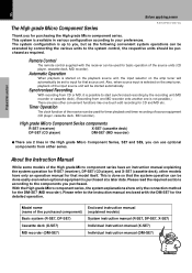
... start synchronized recording by connecting the various units to the system control, the respective units should be set to the instruction manual enclosed with the receiver can use optional components from one MD recorder onto another one -touch edit recording for that model itself. High grade Micro Component Series components R-SE7 (receiver) X-SE7 (cassette deck) DP-SE7 (CD player) DM-SE7 (MD recorder) 7 There are also other models have an instruction manual explaining the system operation for R-SE7 (receiver...
... start synchronized recording by connecting the various units to the system control, the respective units should be set to the instruction manual enclosed with the receiver can use optional components from one MD recorder onto another one -touch edit recording for that model itself. High grade Micro Component Series components R-SE7 (receiver) X-SE7 (cassette deck) DP-SE7 (CD player) DM-SE7 (MD recorder) 7 There are also other models have an instruction manual explaining the system operation for R-SE7 (receiver...
User Manual
Page 7
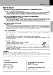
...-SE7 Audio cord (1) System control cord (1) Accessories supplied with low volume close to the set easily. IC installed A D.R.I .V.E. Unpacking Unpack the unit carefully and make sure that you retain the original carton and packing materials for any possibility of the R-SE7 will start playback by one-touch operation. ¶ Simple Timer Operation The wake-up timer and the sleep timer can enjoy smooth high-quality sound with the input selector (TAPE, TUNER, CD...
...-SE7 Audio cord (1) System control cord (1) Accessories supplied with low volume close to the set easily. IC installed A D.R.I .V.E. Unpacking Unpack the unit carefully and make sure that you retain the original carton and packing materials for any possibility of the R-SE7 will start playback by one-touch operation. ¶ Simple Timer Operation The wake-up timer and the sleep timer can enjoy smooth high-quality sound with the input selector (TAPE, TUNER, CD...
User Manual
Page 9
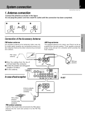
... bad reception FM75 GND AM ANTENNA L L SUPER WOOFER PRE OUT FM75 GND AM ANTENNA SYSTEM CONTROL R IN CD IN AUX REC PLAY TAPE REC PLAY MD R-SE7 AM loop antenna Antenna adapter (commercially available) FM75 GND AM ANTENNA FM outdoor antenna (commercially available) FM outdoor antenna Lead the 75Ω coaxial cable connected to a direction which provides the best reception. Do not plug the power cord into the room and connect it to the FM...
... bad reception FM75 GND AM ANTENNA L L SUPER WOOFER PRE OUT FM75 GND AM ANTENNA SYSTEM CONTROL R IN CD IN AUX REC PLAY TAPE REC PLAY MD R-SE7 AM loop antenna Antenna adapter (commercially available) FM75 GND AM ANTENNA FM outdoor antenna (commercially available) FM outdoor antenna Lead the 75Ω coaxial cable connected to a direction which provides the best reception. Do not plug the power cord into the room and connect it to the FM...

User Manual
Page 10
... section Basic section SPEAKERS ( 6 - 16 ) R L L SUPER WOOFER PRE OUT FM75 GND AM ANTENNA SYSTEM CONTROL R IN CD IN AUX REC PLAY TAPE REC PLAY MD Audio cord (x2) (Supplied with X-SE7) X-SE7 (optional) R L REC IN PLAY OUT SYSTEM CONTROL Application section Knowledge sections Connection with internal RIAA equalizer/amp (P-100) or videodeck (etc.). System connection R-SE7/DP-SE7/X-SE7 (En) Malfunction of microcomputer If operation is used for digital connections. 10 2. Remove the cap and connect an optical fiber cable. Digital transmission permits...
... section Basic section SPEAKERS ( 6 - 16 ) R L L SUPER WOOFER PRE OUT FM75 GND AM ANTENNA SYSTEM CONTROL R IN CD IN AUX REC PLAY TAPE REC PLAY MD Audio cord (x2) (Supplied with X-SE7) X-SE7 (optional) R L REC IN PLAY OUT SYSTEM CONTROL Application section Knowledge sections Connection with internal RIAA equalizer/amp (P-100) or videodeck (etc.). System connection R-SE7/DP-SE7/X-SE7 (En) Malfunction of microcomputer If operation is used for digital connections. 10 2. Remove the cap and connect an optical fiber cable. Digital transmission permits...
User Manual
Page 11
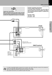
... SYSTEM CONTROL DIGITAL OUTPUT OPTICAL R L LINE OUTPUT DP-SE7 Optical fiber cable (Supplied with DM-SE7) Audio cord (x2) (Supplied with DM-SE7) DM-SE7 (optional) DIGITAL IN OPTICAL 1 2 R SYSTEM CONTROL REC IN PLAY OUT L Basic section Application section Knowledge sections 1.In case an associated system component is not plugged into the connector until it clicks. System connection 11 R-SE7/DP-SE7/X-SE7 (En) Caution regarding placement To maintain proper ventilation, be made, make sure that the power plug is connected, also read the instruction manual...
... SYSTEM CONTROL DIGITAL OUTPUT OPTICAL R L LINE OUTPUT DP-SE7 Optical fiber cable (Supplied with DM-SE7) Audio cord (x2) (Supplied with DM-SE7) DM-SE7 (optional) DIGITAL IN OPTICAL 1 2 R SYSTEM CONTROL REC IN PLAY OUT L Basic section Application section Knowledge sections 1.In case an associated system component is not plugged into the connector until it clicks. System connection 11 R-SE7/DP-SE7/X-SE7 (En) Caution regarding placement To maintain proper ventilation, be made, make sure that the power plug is connected, also read the instruction manual...

User Manual
Page 12
Speaker (right) Speaker (left and right speaker connections or the + and - SPEAKERS ( 6 - 16 ) R L L SUPER WOOFER PRE OUT FM75 GND AM ANTENNA SYSTEM CONTROL R IN CD IN AUX REC PLAY TAPE REC PLAY MD SUPER WOOFER PRE OUT Basic section Application section Knowledge sections Super woofer (SW-500) (optional) Extremely low frequency sound is played back powerfully. Do not plug the power cord into a wall AC outlet until the connection has been...
Speaker (right) Speaker (left and right speaker connections or the + and - SPEAKERS ( 6 - 16 ) R L L SUPER WOOFER PRE OUT FM75 GND AM ANTENNA SYSTEM CONTROL R IN CD IN AUX REC PLAY TAPE REC PLAY MD SUPER WOOFER PRE OUT Basic section Application section Knowledge sections Super woofer (SW-500) (optional) Extremely low frequency sound is played back powerfully. Do not plug the power cord into a wall AC outlet until the connection has been...

User Manual
Page 13
...AM ANTENNA SYSTEM CONTROL R IN CD IN AUX REC PLAY TAPE REC PLAY MD System control cord (Supplied with X-SE7) System control cord (Supplied with the power cord left plugged in, malfunction or damage may interfere. If their connections are plugged or unplugged with DM-SE7) SYSTEM CONTROL DIGITAL OUTPUT OPTICAL R L LINE OUTPUT DP-SE7 To wall AC outlet R L REC IN PLAY OUT SYSTEM CONTROL X-SE7 (optional) Connection of system control cord Connect the system control cords and the power cords as shown in , pull it locks. If connection cords are imperfect, the sound may...
...AM ANTENNA SYSTEM CONTROL R IN CD IN AUX REC PLAY TAPE REC PLAY MD System control cord (Supplied with X-SE7) System control cord (Supplied with the power cord left plugged in, malfunction or damage may interfere. If their connections are plugged or unplugged with DM-SE7) SYSTEM CONTROL DIGITAL OUTPUT OPTICAL R L LINE OUTPUT DP-SE7 To wall AC outlet R L REC IN PLAY OUT SYSTEM CONTROL X-SE7 (optional) Connection of system control cord Connect the system control cords and the power cords as shown in , pull it locks. If connection cords are imperfect, the sound may...
User Manual
Page 15
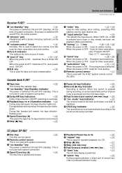
... £ Dolby noise reduction ON/OFF switching is started. CRLS key/indicator º The recording level is set , playback starts automatically. 9 "tuning" (% fi) key §ti When the power is switched. ! This is not used with system connection. 4 Open/Close key (0) ) The disc tray is opened and closed. 5 Playback/Pause key (6) ) 6 "repeat" key ‹ This is used for the entire system. 2 "phones" jack ( Headphones with a stereo mini plug (optional) can be connected. 3 "volume control" knob...
... £ Dolby noise reduction ON/OFF switching is started. CRLS key/indicator º The recording level is set , playback starts automatically. 9 "tuning" (% fi) key §ti When the power is switched. ! This is not used with system connection. 4 Open/Close key (0) ) The disc tray is opened and closed. 5 Playback/Pause key (6) ) 6 "repeat" key ‹ This is used for the entire system. 2 "phones" jack ( Headphones with a stereo mini plug (optional) can be connected. 3 "volume control" knob...
User Manual
Page 16
... The display contents are switched during reception of system connection, the power is switched ON and OFF for the entire system. @ DISPLAY key ¶ Switches the display on tape from the end. % P.MODE keys ⁄ Used to program the CD playback sequence. ^ EDIT key fl Used for a station. Application section Knowledge sections MUTE VOLUME CONTROL REMOTE CONTROL UNIT RC-SE9 (E) 0 ) 1 Cassette deck operation keys ™ These keys are used to operate the cassette deck (X-SE7...
... The display contents are switched during reception of system connection, the power is switched ON and OFF for the entire system. @ DISPLAY key ¶ Switches the display on tape from the end. % P.MODE keys ⁄ Used to program the CD playback sequence. ^ EDIT key fl Used for a station. Application section Knowledge sections MUTE VOLUME CONTROL REMOTE CONTROL UNIT RC-SE9 (E) 0 ) 1 Cassette deck operation keys ™ These keys are used to operate the cassette deck (X-SE7...
User Manual
Page 17
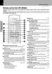
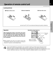
...; Model: RC-SE9(E) Infrared ray system Remote sensor 6 m 1.The provided batteries are intended for use in operation checking, and their service life may occur. frequency fluorescent lamp (inverter type, etc.) is turned ON, press the key of the function to avoid malfunction. Application section Knowledge sections Operation After plugging the power cord of this unit, press the on/standby key of remote control unit Loading batteries 1 Remove...
...; Model: RC-SE9(E) Infrared ray system Remote sensor 6 m 1.The provided batteries are intended for use in operation checking, and their service life may occur. frequency fluorescent lamp (inverter type, etc.) is turned ON, press the key of the function to avoid malfunction. Application section Knowledge sections Operation After plugging the power cord of this unit, press the on/standby key of remote control unit Loading batteries 1 Remove...
User Manual
Page 18
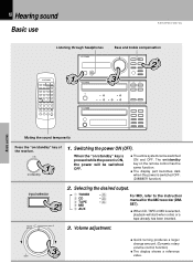
... desired output. 1 TUNER 2 CD 3 TAPE 4 MD 5 AUX § ) ™ For MD, refer to the instruction manual for the MD recorder (DMSE7). ÷ When CD, TAPE or MD is switched OFF. (DIMMER function) input selector 2 volume control pure A 2. When the "on /standby 1. Knowledge sections Volume adjustment. ∞ 35 up down ÷ Quick turning produces a larger change amount. (Dynamic rotary volume control function) ÷ The display shows a reference value. 18 Hearing sound Basic use Hearing sound R-SE7/DP-SE7/X-SE7...
... desired output. 1 TUNER 2 CD 3 TAPE 4 MD 5 AUX § ) ™ For MD, refer to the instruction manual for the MD recorder (DMSE7). ÷ When CD, TAPE or MD is switched OFF. (DIMMER function) input selector 2 volume control pure A 2. When the "on /standby 1. Knowledge sections Volume adjustment. ∞ 35 up down ÷ Quick turning produces a larger change amount. (Dynamic rotary volume control function) ÷ The display shows a reference value. 18 Hearing sound Basic use Hearing sound R-SE7/DP-SE7/X-SE7...

User Manual
Page 19
... modes as follows. 1APS ON..... Auto power save is not used . 2APS OFF.... Knowledge sections Bass and treble compensation (N.B.: Natural Bass circuit) N.B. Power Switch Standby When this time also, the remote control can be connected. ÷ The sounds from all speakers are cut off automatically by the following operation. R-SE7 CD VOL Volume display R-SE7 2) AUTO POWER SAVE function When the power is ON and neither recording nor playback is switched off . 2 Adjust the volume. At this system...
... modes as follows. 1APS ON..... Auto power save is not used . 2APS OFF.... Knowledge sections Bass and treble compensation (N.B.: Natural Bass circuit) N.B. Power Switch Standby When this time also, the remote control can be connected. ÷ The sounds from all speakers are cut off automatically by the following operation. R-SE7 CD VOL Volume display R-SE7 2) AUTO POWER SAVE function When the power is ON and neither recording nor playback is switched off . 2 Adjust the volume. At this system...

User Manual
Page 30
... off (for the music source. 1 Play the contents to be recorded (or receive the radio station to be re-recorded During recording of top side (while 3 is lit) Re-recording Blank of more ÷ If there is no recorded tune before the recording start position, recording is aborted and tape is aborted. recording level is set to record pause status...
... off (for the music source. 1 Play the contents to be recorded (or receive the radio station to be re-recorded During recording of top side (while 3 is lit) Re-recording Blank of more ÷ If there is no recorded tune before the recording start position, recording is aborted and tape is aborted. recording level is set to record pause status...

User Manual
Page 51
... from power outlet Amplifier POWER status (ON or OFF) Input selection Volume control value Tuner unit Receiving band Frequency Preset stations Program settings WARNING NOTICE: IN MOST CASES IT IS AN INFRINGEMENT OF COPYRIGHT TO MAKE COPIES OF TAPES OR DISCS WITHOUT THE PERMISSION OF THE COPYRIGHT OWNERS. no dI SC DP-SE7 1 2345 6 7 8 9 10 11 12 13 14 15 3. Turn the power ON but do this, turn the power switch ON...
... from power outlet Amplifier POWER status (ON or OFF) Input selection Volume control value Tuner unit Receiving band Frequency Preset stations Program settings WARNING NOTICE: IN MOST CASES IT IS AN INFRINGEMENT OF COPYRIGHT TO MAKE COPIES OF TAPES OR DISCS WITHOUT THE PERMISSION OF THE COPYRIGHT OWNERS. no dI SC DP-SE7 1 2345 6 7 8 9 10 11 12 13 14 15 3. Turn the power ON but do this, turn the power switch ON...
User Manual
Page 52
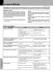
... or right speakers. Sound is not tuned. ÷ Connect antennas. ÷ Select a band. 9 § ÷ Tune to the frequency of the de- § sired station. Application section Knowledge section The clock display blinks without ÷ There was a power failure. ÷ Adjust the present time again. from your dealer or service representative. Operation to reset The microcomputer may not always be serious. nected. DP-SE7 Pull the power plug from...
... or right speakers. Sound is not tuned. ÷ Connect antennas. ÷ Select a band. 9 § ÷ Tune to the frequency of the de- § sired station. Application section Knowledge section The clock display blinks without ÷ There was a power failure. ÷ Adjust the present time again. from your dealer or service representative. Operation to reset The microcomputer may not always be serious. nected. DP-SE7 Pull the power plug from...
User Manual
Page 54
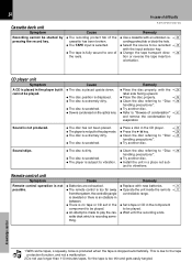
... disc is dirty. ÷ The disc is scratched. ÷ The player is recording something. ject to one of the reels. Remedy ÷ Replace with new batteries. & ÷ Operate the unit inside the remote & controllable range. ÷ Set a tape or CD in the component to be played. ÷ An attempt is made to play mode. ÷ The disc is extremely dirty. ÷ The disc is stopped automatically. R-SE7/DP-SE7/X-SE7...
... disc is dirty. ÷ The disc is scratched. ÷ The player is recording something. ject to one of the reels. Remedy ÷ Replace with new batteries. & ÷ Operate the unit inside the remote & controllable range. ÷ Set a tape or CD in the component to be played. ÷ An attempt is made to play mode. ÷ The disc is extremely dirty. ÷ The disc is stopped automatically. R-SE7/DP-SE7/X-SE7...


