
Instruction Manual
Page 1
Model Name NX-200 NX-300 NX-200G NX-300G Area North America Language English French Spanish NX-210 NX-210G NX-410 NX-411 North America English French Spanish NX-220 NX-320 NX-420 North America English French Spanish NX-240 NX-240V NX-340 NX-340U North America English French Spanish File View View File Number B62-2608-10 View B5A-0001-10 View View B62-2470-10 B62-2580-10 © 2017 B5K-0417-00 INSTRUCTION MANUAL LIST DIGITAL TRANSCEIVER NX-x00 series NX-x10 series NX-x20 series NX-x40 series To download the instruction manual data, press [View] and save the PDF file.
Model Name NX-200 NX-300 NX-200G NX-300G Area North America Language English French Spanish NX-210 NX-210G NX-410 NX-411 North America English French Spanish NX-220 NX-320 NX-420 North America English French Spanish NX-240 NX-240V NX-340 NX-340U North America English French Spanish File View View File Number B62-2608-10 View B5A-0001-10 View View B62-2470-10 B62-2580-10 © 2017 B5K-0417-00 INSTRUCTION MANUAL LIST DIGITAL TRANSCEIVER NX-x00 series NX-x10 series NX-x20 series NX-x40 series To download the instruction manual data, press [View] and save the PDF file.
Instruction Manual 1
Page 3
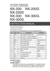
... I Serial Data Input CMOS 14 NC - Not used - VHF DIGITAL TRANSCEIVER UHF DIGITAL TRANSCEIVER NX-200 NX-200G NX-200S NX-300 NX-300G NX-300S INSTRUCTION MANUAL Terminal Descriptions Universal connector It is mounted on the rear side of the transceiver using a sliding mounting method. External MIC GND GND 7 PTT I External PTT Input High Impedance 8 PF I Programmable Function Key Input High Impedance 9 OPT I/O Man Down Input High Impedance 10 E − GND GND 11 5V O 5V power supply output 5 V 12 TXD O Serial Data Output CMOS...
... I Serial Data Input CMOS 14 NC - Not used - VHF DIGITAL TRANSCEIVER UHF DIGITAL TRANSCEIVER NX-200 NX-200G NX-200S NX-300 NX-300G NX-300S INSTRUCTION MANUAL Terminal Descriptions Universal connector It is mounted on the rear side of the transceiver using a sliding mounting method. External MIC GND GND 7 PTT I External PTT Input High Impedance 8 PF I Programmable Function Key Input High Impedance 9 OPT I/O Man Down Input High Impedance 10 E − GND GND 11 5V O 5V power supply output 5 V 12 TXD O Serial Data Output CMOS...

Instruction Manual 1
Page 6
... which can generate radio frequency energy and, if not installed and used in accordance with your area, call (toll free) 1-800-8-BATTERY (1-800-822-8837). The RBRC program is connected. • Consult the dealer for a Class B digital device, pursuant to provide reasonable protection against harmful interference in a residential installation. ii The user could lose the authority to operate this program is made. If...
... which can generate radio frequency energy and, if not installed and used in accordance with your area, call (toll free) 1-800-8-BATTERY (1-800-822-8837). The RBRC program is connected. • Consult the dealer for a Class B digital device, pursuant to provide reasonable protection against harmful interference in a residential installation. ii The user could lose the authority to operate this program is made. If...

Instruction Manual 1
Page 7
... the transceiver and the battery pack. • Do not use options not specified by KENWOOD. • If the die-cast chassis or other transceiver part is damaged, do not touch the damaged parts. • If a headset or headphone is connected to the volume level when turning the squelch off before installing optional accessories. • The charger is used for transmission for many...
... the transceiver and the battery pack. • Do not use options not specified by KENWOOD. • If the die-cast chassis or other transceiver part is damaged, do not touch the damaged parts. • If a headset or headphone is connected to the volume level when turning the squelch off before installing optional accessories. • The charger is used for transmission for many...

Instruction Manual 1
Page 13
...1 SUPPLIED ACCESSORIES 1 PREPARATION 2 INSTALLING/ REMOVING THE (OPTIONAL) BATTERY PACK 2 INSTALLING THE (OPTIONAL) ANTENNA 2 INSTALLING THE BELT CLIP 3 INSTALLING THE CAP OVER THE UNIVERSAL CONNECTOR 3 INSTALLING THE (OPTIONAL) SPEAKER/ MICROPHONE OR HEADSET ..... 3 GETTING ACQUAINTED 4 DISPLAY 7 PROGRAMMABLE FUNCTIONS 8 BASIC OPERATIONS 12 SWITCHING POWER ON/ OFF 12 ADJUSTING THE VOLUME 12 SELECTING A ZONE AND CHANNEL/GROUP ID 13 TRANSMITTING 13 RECEIVING 14 MENU MODE (NX-200/ NX-300/ NX-200G/ NX300G ONLY) ....15 MENU ACCESS 15 MENU CONFIGURATION 15 CHARACTER ENTRY 17 SCAN...
...1 SUPPLIED ACCESSORIES 1 PREPARATION 2 INSTALLING/ REMOVING THE (OPTIONAL) BATTERY PACK 2 INSTALLING THE (OPTIONAL) ANTENNA 2 INSTALLING THE BELT CLIP 3 INSTALLING THE CAP OVER THE UNIVERSAL CONNECTOR 3 INSTALLING THE (OPTIONAL) SPEAKER/ MICROPHONE OR HEADSET ..... 3 GETTING ACQUAINTED 4 DISPLAY 7 PROGRAMMABLE FUNCTIONS 8 BASIC OPERATIONS 12 SWITCHING POWER ON/ OFF 12 ADJUSTING THE VOLUME 12 SELECTING A ZONE AND CHANNEL/GROUP ID 13 TRANSMITTING 13 RECEIVING 14 MENU MODE (NX-200/ NX-300/ NX-200G/ NX300G ONLY) ....15 MENU ACCESS 15 MENU CONFIGURATION 15 CHARACTER ENTRY 17 SCAN...

Instruction Manual 1
Page 16
... to the battery charger Instruction Manual. ◆ Before charging a battery pack that is attached to the transceiver, ensure that the safety catch is firmly closed. ◆ While operating the transceiver using a Li-ion battery pack in areas with the grooves on the top of -10°C/ +14°F and lower, operating time may be shortened. ◆ Install the battery pack after...
... to the battery charger Instruction Manual. ◆ Before charging a battery pack that is attached to the transceiver, ensure that the safety catch is firmly closed. ◆ While operating the transceiver using a Li-ion battery pack in areas with the grooves on the top of -10°C/ +14°F and lower, operating time may be shortened. ◆ Install the battery pack after...

Instruction Manual 1
Page 18
... your dealer, lights red while transmitting, green while receiving a call (Conventional channels only), and orange when receiving an optional signaling call a station. The default is low while transmitting. g Side 2 key Press to activate its programmable function {page 8}. h Universal connector Connect a speaker/ microphone or headset here {page 3}. b Power switch/ Volume control Rotate to turn the transceiver ON/OFF and to activate its programmable function {page 8}. Blinks red when the battery power is Squelch Off Momentary. Otherwise...
... your dealer, lights red while transmitting, green while receiving a call (Conventional channels only), and orange when receiving an optional signaling call a station. The default is low while transmitting. g Side 2 key Press to activate its programmable function {page 8}. h Universal connector Connect a speaker/ microphone or headset here {page 3}. b Power switch/ Volume control Rotate to turn the transceiver ON/OFF and to activate its programmable function {page 8}. Blinks red when the battery power is Squelch Off Momentary. Otherwise...
Instruction Manual 1
Page 26
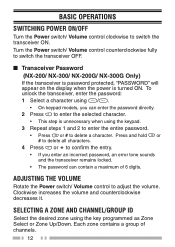
... zone using / . • On keypad models, you enter an incorrect password, an error tone sounds and the transceiver remains locked. • The password can enter the password directly. 2 Press to confirm the entry. • If you can contain a maximum of channels. 12 Each zone contains a group of 6 digits. ADJUSTING THE VOLUME Rotate the Power switch/ Volume control to switch the transceiver ON. BASIC OPERATIONS SWITCHING POWER ON/OFF Turn the Power switch/ Volume control...
... zone using / . • On keypad models, you enter an incorrect password, an error tone sounds and the transceiver remains locked. • The password can enter the password directly. 2 Press to confirm the entry. • If you can contain a maximum of channels. 12 Each zone contains a group of 6 digits. ADJUSTING THE VOLUME Rotate the Power switch/ Volume control to switch the transceiver ON. BASIC OPERATIONS SWITCHING POWER ON/OFF Turn the Power switch/ Volume control...
Instruction Manual 1
Page 27
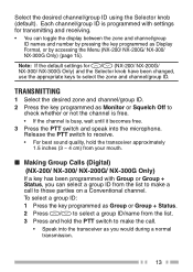
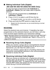
... from the list. 3 Press and hold the transceiver approximately 1.5 inches (3 ~ 4 cm) from your mouth. ■ Making Group Calls (Digital) (NX-200/ NX-300/ NX-200G/ NX-300G Only) If a key has been programmed with settings for / (NX-200/ NX-200G/ NX-300/ NX-300G Only) and the Selector knob have been changed, use the appropriate keys to check whether or not the channel is free. • If the channel is programmed with...
... from the list. 3 Press and hold the transceiver approximately 1.5 inches (3 ~ 4 cm) from your mouth. ■ Making Group Calls (Digital) (NX-200/ NX-300/ NX-200G/ NX-300G Only) If a key has been programmed with settings for / (NX-200/ NX-200G/ NX-300/ NX-300G Only) and the Selector knob have been changed, use the appropriate keys to check whether or not the channel is free. • If the channel is programmed with...
Instruction Manual 1
Page 28
... received signal matches your calls. To respond to the call on a Conventional channel and the received group ID matches the ID set up on your transceiver, you can enter a unit ID directly. 3 Press and hold the PTT switch and speak into the transceiver as you would during a normal transmission. ■ Making Individual Calls (Digital) (NX-200/ NX-300/ NX-200G/ NX-300G Only) If a key...
... received signal matches your calls. To respond to the call on a Conventional channel and the received group ID matches the ID set up on your transceiver, you can enter a unit ID directly. 3 Press and hold the PTT switch and speak into the transceiver as you would during a normal transmission. ■ Making Individual Calls (Digital) (NX-200/ NX-300/ NX-200G/ NX-300G Only) If a key...
Instruction Manual 1
Page 29
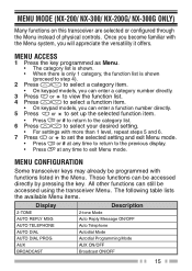
... using the transceiver Menu. Those functions can enter a category number directly. 3 Press or to view the function list. 4 Press / to select a function item. • On keypad models, you will appreciate the versatility it offers. All other functions can enter a function number directly. 5 Press or to set the selected setting and exit Menu mode. • Press or # at any time to return to the previous display...
... using the transceiver Menu. Those functions can enter a category number directly. 3 Press or to view the function list. 4 Press / to select a function item. • On keypad models, you will appreciate the versatility it offers. All other functions can enter a function number directly. 5 Press or to set the selected setting and exit Menu mode. • Press or # at any time to return to the previous display...

Instruction Manual 1
Page 30
... LOW CUT SCAN SCAN DEL/ADD SCRAM/ENCRYP SCRAM CODE SELCALL SELCALL+STATUS SELCALL+SDM SEND GPS DATA SITE LOCK 16 Description Clock ON/OFF Clock Adjustment mode Direct CH/GID 1 ~ 5 Select Display Format ON/OFF External Microphone Type mode Fixed Volume Forced Search GPS Position Display mode Group mode Group + Status mode Group + SDM mode High Transmisson Power ON/OFF Home CH/GID Select Individual mode Individual + Status mode Individual + SDM mode Lone Worker...
... LOW CUT SCAN SCAN DEL/ADD SCRAM/ENCRYP SCRAM CODE SELCALL SELCALL+STATUS SELCALL+SDM SEND GPS DATA SITE LOCK 16 Description Clock ON/OFF Clock Adjustment mode Direct CH/GID 1 ~ 5 Select Display Format ON/OFF External Microphone Type mode Fixed Volume Forced Search GPS Position Display mode Group mode Group + Status mode Group + SDM mode High Transmisson Power ON/OFF Home CH/GID Select Individual mode Individual + Status mode Individual + SDM mode Lone Worker...
Instruction Manual 1
Page 34
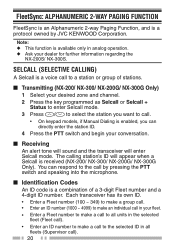
... channel. 2 Press the key programmed as Selcall or Selcall + Status to enter Selcall mode. 3 Press / to select the station you want to call. • On keypad models, if Manual Dialing is enabled, you can respond to the call by JVC KENWOOD Corporation. You can directly enter the station ID. 4 Press the PTT switch and begin your dealer for further information regarding the NX-200S/ NX...
... channel. 2 Press the key programmed as Selcall or Selcall + Status to enter Selcall mode. 3 Press / to select the station you want to call. • On keypad models, if Manual Dialing is enabled, you can respond to the call by JVC KENWOOD Corporation. You can directly enter the station ID. 4 Press the PTT switch and begin your dealer for further information regarding the NX-200S/ NX...
Instruction Manual 1
Page 35
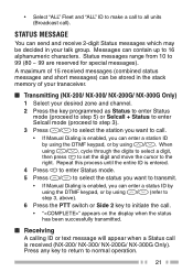
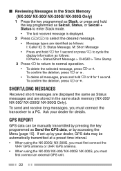
... enter a status ID by using the DTMF keypad, or by using / , cycle through the digits to select a digit, then press to set the digit and move the cursor to the right. • Select "ALL" Fleet and "ALL" ID to make a call to all units (Broadcast call . • If Manual Dialing is received (NX-200/ NX-300/ NX-200G/ NX-300G Only). STATUS MESSAGE You...
... enter a status ID by using the DTMF keypad, or by using / , cycle through the digits to select a digit, then press to set the digit and move the cursor to the right. • Select "ALL" Fleet and "ALL" ID to make a call to all units (Broadcast call . • If Manual Dialing is received (NX-200/ NX-300/ NX-200G/ NX-300G Only). STATUS MESSAGE You...
Instruction Manual 1
Page 36
.... Ask your dealer, GPS data may be automatically transmitted at a preset time interval. • When using the NX-200G/ NX-300G, you must first connect the VHF/ GPS antenna or UHF/ GPS antenna. • When using the NX-200/ NX-300/ NX-200S/ NX-300S, you must first connect an external GPS unit. 22 To confirm the deletion, press or . SHORT/LONG MESSAGES Received short messages are displayed the same as...
.... Ask your dealer, GPS data may be automatically transmitted at a preset time interval. • When using the NX-200G/ NX-300G, you must first connect the VHF/ GPS antenna or UHF/ GPS antenna. • When using the NX-200/ NX-300/ NX-200S/ NX-300S, you must first connect an external GPS unit. 22 To confirm the deletion, press or . SHORT/LONG MESSAGES Received short messages are displayed the same as...

Instruction Manual 1
Page 39
... key programmed as Emergency. • Ask your dealer for the length of time necessary to hold this key before the transceiver enters Emergency mode. • When the transceiver enters Emergency mode, it will change to the Emergency channel and begin transmitting based on how it is set the transceiver to emit tones and received signals as Scrambler/ Encryption, or access the Menu...
... key programmed as Emergency. • Ask your dealer for the length of time necessary to hold this key before the transceiver enters Emergency mode. • When the transceiver enters Emergency mode, it will change to the Emergency channel and begin transmitting based on how it is set the transceiver to emit tones and received signals as Scrambler/ Encryption, or access the Menu...
Instruction Manual 1
Page 41
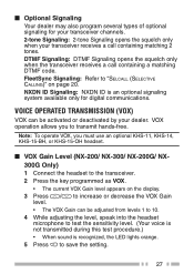
... channels. 2-tone Signaling: 2-tone Signaling opens the squelch only when your dealer. VOICE OPERATED TRANSMISSION (VOX) VOX can be activated or deactivated by your transceiver receives a call containing a matching DTMF code. VOX operation allows you must use an optional KHS-11, KHS-14, KHS-15-BH, or KHS-15-OH headset. ■ VOX Gain Level (NX-200/ NX-300/ NX-200G/ NX300G Only) 1 Connect the headset...
... channels. 2-tone Signaling: 2-tone Signaling opens the squelch only when your dealer. VOICE OPERATED TRANSMISSION (VOX) VOX can be activated or deactivated by your transceiver receives a call containing a matching DTMF code. VOX operation allows you must use an optional KHS-11, KHS-14, KHS-15-BH, or KHS-15-OH headset. ■ VOX Gain Level (NX-200/ NX-300/ NX-200G/ NX300G Only) 1 Connect the headset...

Instruction Manual 1
Page 43
... sound. TIME-OUT TIMER (TOT) The Time-out Timer is used to turn the Vibrator function ON and OFF. If you from using a channel for a preset time, the transceiver will stop transmitting and an alert tone will clear the clock time. CLOCK (NX-200/ NX-300/ NX-200G/ NX-300G ONLY) If activated by your part. VIBRATOR When an optional vibrator is received. To set the clock: 1 Press the key programmed...
... sound. TIME-OUT TIMER (TOT) The Time-out Timer is used to turn the Vibrator function ON and OFF. If you from using a channel for a preset time, the transceiver will stop transmitting and an alert tone will clear the clock time. CLOCK (NX-200/ NX-300/ NX-200G/ NX-300G ONLY) If activated by your part. VIBRATOR When an optional vibrator is received. To set the clock: 1 Press the key programmed...

Instruction Manual 1
Page 45
... digital Trunking channels, the transceiver automatically searches for a control channel. • While searching for a channel, the compander will be unable to provide higher clarity of range (NXDN Trunking only). PTT ID PTT ID is the transceiver unique ID code which is sent each time the PTT switch is already in analog operation. 31 COMPANDER If programmed by your dealer for a control channel, the antenna icon will sound. 2 Quickly...
... digital Trunking channels, the transceiver automatically searches for a control channel. • While searching for a channel, the compander will be unable to provide higher clarity of range (NXDN Trunking only). PTT ID PTT ID is the transceiver unique ID code which is sent each time the PTT switch is already in analog operation. 31 COMPANDER If programmed by your dealer for a control channel, the antenna icon will sound. 2 Quickly...
User Manual
Page 1
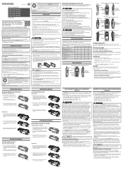
... eye-problems. WARNING • Do not charge the battery for belt clip Universal connector cap • Dressing screw • Packing User guide NX-x00 1 2 1 1 1 1 NX-x10 1 2 1 1 - 1 NX-x20 - - - 1 1 1 1 - - - - 1 NX-x40 1 1 1 1 1 1 1 2 - - - 1 NX-420 1 - - 1 1 1 1 - - - - 1 BASIC OPERATION Selector knob Antenna Display Power switch/ Volume control PTT Switch Microphone Speaker Keypad MIC 1 4 GHI 7 PQRS 2 ABC 5 JKL 8 TUV 0 3 DEF 6 MNO 9 WXYZ # Universal connector Battery Pack Selector knob Antenna PTT Switch Speaker Microphone Display Power switch/ Volume control Universal...
... eye-problems. WARNING • Do not charge the battery for belt clip Universal connector cap • Dressing screw • Packing User guide NX-x00 1 2 1 1 1 1 NX-x10 1 2 1 1 - 1 NX-x20 - - - 1 1 1 1 - - - - 1 NX-x40 1 1 1 1 1 1 1 2 - - - 1 NX-420 1 - - 1 1 1 1 - - - - 1 BASIC OPERATION Selector knob Antenna Display Power switch/ Volume control PTT Switch Microphone Speaker Keypad MIC 1 4 GHI 7 PQRS 2 ABC 5 JKL 8 TUV 0 3 DEF 6 MNO 9 WXYZ # Universal connector Battery Pack Selector knob Antenna PTT Switch Speaker Microphone Display Power switch/ Volume control Universal...


