Instruction Manual
Page 2
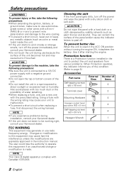
...your unit to peel off the power immediately and consult your Kenwood dealer. • Do not touch the unit during installation, consult your Kenwood dealer. • If the unit does not seem to be working right, consult your Kenwood dealer. They can scratch the surface of water splashing. &#...-003. Safety precautions 2WARNING To prevent injury or fire, take the following precautions: • When extending the ignition, battery, or ground wires, make sure to use radio frequency energy. The user could lose the authority to operate this equipment may cause burns if touched. 2CAUTION ...
...your unit to peel off the power immediately and consult your Kenwood dealer. • Do not touch the unit during installation, consult your Kenwood dealer. • If the unit does not seem to be working right, consult your Kenwood dealer. They can scratch the surface of water splashing. &#...-003. Safety precautions 2WARNING To prevent injury or fire, take the following precautions: • When extending the ignition, battery, or ground wires, make sure to use radio frequency energy. The user could lose the authority to operate this equipment may cause burns if touched. 2CAUTION ...
Instruction Manual
Page 3
... cooling fan openings when installing the unit. English 3 Install the amplifier in the vehicle, check that electrical equipment such as a gasoline tank, brake pipe, or wiring harness, and be damaged. • Install this unit in the unit. 2. Once installed, do not place any object on the opposite side such as the...
... cooling fan openings when installing the unit. English 3 Install the amplifier in the vehicle, check that electrical equipment such as a gasoline tank, brake pipe, or wiring harness, and be damaged. • Install this unit in the unit. 2. Once installed, do not place any object on the opposite side such as the...
Instruction Manual
Page 5
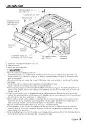
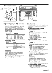
... 't supply enough current. • The color blinks purple When the unit has failed and direct current voltage is the B.M.S. When the battery wire is in contact with the variable color button. • The color blinks blue - When the speaker cord is less than 11V. switch controls... • The color blinks yellow When the power voltage is shorted. - FREQUENCY control adjustment value. If the indicator doesn't quit blinking, contact your Kenwood dealer. • The color blinks red When the inside of the unit is 20- 30% low. "Low" The central frequency is overheating. &#...
... 't supply enough current. • The color blinks purple When the unit has failed and direct current voltage is the B.M.S. When the battery wire is in contact with the variable color button. • The color blinks blue - When the speaker cord is less than 11V. switch controls... • The color blinks yellow When the power voltage is shorted. - FREQUENCY control adjustment value. If the indicator doesn't quit blinking, contact your Kenwood dealer. • The color blinks red When the inside of the unit is 20- 30% low. "Low" The central frequency is overheating. &#...
Instruction Manual
Page 6
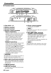
wire attached can be connected should have an impedance of the amplifier. The speakers to be used. NOTE There are cases when operation may result. ^ RCA ... ■ Terminal names FUSE(30Ax2) POWER IN BATT. Fuse (30 A × 2) @ Battery terminal # Ground terminal % Speaker output terminals • Stereo Connections: When you wish to wiring wire type and length. When multiple speakers are used . Only Kenwood center unit models sold in 1999 or later with a "EXT.CONT."/"EXT.AMP.CONT."
wire attached can be connected should have an impedance of the amplifier. The speakers to be used. NOTE There are cases when operation may result. ^ RCA ... ■ Terminal names FUSE(30Ax2) POWER IN BATT. Fuse (30 A × 2) @ Battery terminal # Ground terminal % Speaker output terminals • Stereo Connections: When you wish to wiring wire type and length. When multiple speakers are used . Only Kenwood center unit models sold in 1999 or later with a "EXT.CONT."/"EXT.AMP.CONT."
Instruction Manual
Page 7
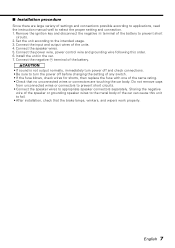
...this order. 6. Do not remove caps from unconnected wires or connectors to prevent short circuits. • Connect the speaker wires to the intended usage. 3. Connect the power wire, power control wire and grounding wire following this unit to turn the power off before ...the unit according to appropriate speaker connectors separately. Connect the speaker wires. 5. Connect the negative - English 7 terminal of the units. 4. Sharing the negative wire of the speaker or grounding speaker wires to the metal body of settings and connections possible according to applications...
...this order. 6. Do not remove caps from unconnected wires or connectors to prevent short circuits. • Connect the speaker wires to the intended usage. 3. Connect the power wire, power control wire and grounding wire following this unit to turn the power off before ...the unit according to appropriate speaker connectors separately. Connect the speaker wires. 5. Connect the negative - English 7 terminal of the units. 4. Sharing the negative wire of the speaker or grounding speaker wires to the metal body of settings and connections possible according to applications...
Instruction Manual
Page 8
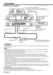
... 2. terminal. OFF REMOTE +12dB FILTER OFF HPF LPF ( OPERATION STEREO MONO(L ch) GND LINE IN LINE OUT EXT.AMP.CONT. Wiring •Take the battery wire for a length of 11mm from the speakers when the engine is running, connect a line noise filter (optional) to install a protective ... passing electricity to be the same capacity as the unit's fuse capacity or somewhat larger. • For the power cord and ground, use a power supply wiring wire and protective fuse of 8 mm2 (AWG 8) or greater.) • When more than one power amplifier are going to the battery's negative - L L R...
... 2. terminal. OFF REMOTE +12dB FILTER OFF HPF LPF ( OPERATION STEREO MONO(L ch) GND LINE IN LINE OUT EXT.AMP.CONT. Wiring •Take the battery wire for a length of 11mm from the speakers when the engine is running, connect a line noise filter (optional) to install a protective ... passing electricity to be the same capacity as the unit's fuse capacity or somewhat larger. • For the power cord and ground, use a power supply wiring wire and protective fuse of 8 mm2 (AWG 8) or greater.) • When more than one power amplifier are going to the battery's negative - L L R...
Instruction Manual
Page 9
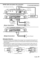
... BATT. OFF REMOTE +12dB FILTER OFF HPF LPF OPERATION STEREO MONO(L ch) GND LINE IN LINE OUT EXT.AMP.CONT. ■ RCA cable and speaker wire connection RCA cable ground terminal ^& INFRASONIC OFF ON B.M.S.
... BATT. OFF REMOTE +12dB FILTER OFF HPF LPF OPERATION STEREO MONO(L ch) GND LINE IN LINE OUT EXT.AMP.CONT. ■ RCA cable and speaker wire connection RCA cable ground terminal ^& INFRASONIC OFF ON B.M.S.
Instruction Manual
Page 12
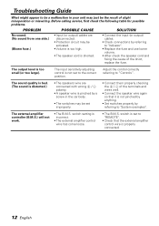
...of slight misoperation or miswiring. switch is set to the correct position. The output level is incorrect. • The external amplifier control wire has come loose. • The B.M.S. Adjust the control correctly referring to "Controls". Before calling service, first check the following table.... (No sound from one side.) (Blown fuse.) • Input (or output) cables are connected with wrong + / polarity. • A speaker wire is pinched by a screw in your unit may be set improperly. • Connect them properly checking the + / - Troubleshooting Guide What might appear to...
...of slight misoperation or miswiring. switch is set to the correct position. The output level is incorrect. • The external amplifier control wire has come loose. • The B.M.S. Adjust the control correctly referring to "Controls". Before calling service, first check the following table.... (No sound from one side.) (Blown fuse.) • Input (or output) cables are connected with wrong + / polarity. • A speaker wire is pinched by a screw in your unit may be set improperly. • Connect them properly checking the + / - Troubleshooting Guide What might appear to...


