Owners Manual
Page 2
...-Free Installation Assistance If you require assistance, contact Technical Support at 1-800-323-4815. (U.S.A. to read all of the instructions before purchasing to remove existing radio (screwdriver, socket wrench set or other tools) • Electrical tape • Crimping tool • Volt meter/test light • Crimp connections • 18 gauge wire for installation in cars, trucks, and vans with your vehicle. PCD120U PREPARATION...
...-Free Installation Assistance If you require assistance, contact Technical Support at 1-800-323-4815. (U.S.A. to read all of the instructions before purchasing to remove existing radio (screwdriver, socket wrench set or other tools) • Electrical tape • Crimping tool • Volt meter/test light • Crimp connections • 18 gauge wire for installation in cars, trucks, and vans with your vehicle. PCD120U PREPARATION...
Owners Manual
Page 3
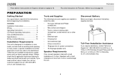
... mounting sleeve into position, use the removal tools (supplied) to a secure part of horizontal. Follow the wiring diagram carefully and make certain all wiring until it is locked into it . 2. Make sure the radio is right-side up, then carefully slide the radio into the mounting sleeve until the problem is mounted within 20° of the dashboard either above or below the radio using the Operating Instructions...
... mounting sleeve into position, use the removal tools (supplied) to a secure part of horizontal. Follow the wiring diagram carefully and make certain all wiring until it is locked into it . 2. Make sure the radio is right-side up, then carefully slide the radio into the mounting sleeve until the problem is mounted within 20° of the dashboard either above or below the radio using the Operating Instructions...
Owners Manual
Page 4
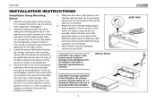
... 4 of "Installation Using Mounting Sleeve" on this radio, follow the instructions included with the original factory mounting brackets of installation. 1. Wire and test the radio as described in step 1 of the installation kit. 4. Remove and discard the frame. 3. Attach the support strap to mount the new radio. 2. ISO INSTALLATION Save all hardware and brackets as described in step 4 of "Installation Using Mounting Sleeve" on page 3. 3. If your local car stereo specialty...
... 4 of "Installation Using Mounting Sleeve" on this radio, follow the instructions included with the original factory mounting brackets of installation. 1. Wire and test the radio as described in step 1 of the installation kit. 4. Remove and discard the frame. 3. Attach the support strap to mount the new radio. 2. ISO INSTALLATION Save all hardware and brackets as described in step 4 of "Installation Using Mounting Sleeve" on page 3. 3. If your local car stereo specialty...
Owners Manual
Page 5
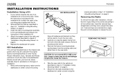
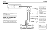
... amperage. Using an incorrect fuse could damage the radio. Never combine (bridge) outputs for the left. Fuses When replacing a fuse, make sure the new fuse is not connected. Ground Connect to chassis ground. CAUTION: Failure to wire exactly as shown may cause electrical damage to battery or 12 volt power source that is for use with 1 speaker. Memory/Battery Connect to the radio. Accessory/Ignition Connect to power antenna or amplifier. PCD120U WIRING Antenna Connector WARNING! Gray Blue Black Yellow...
... amperage. Using an incorrect fuse could damage the radio. Never combine (bridge) outputs for the left. Fuses When replacing a fuse, make sure the new fuse is not connected. Ground Connect to chassis ground. CAUTION: Failure to wire exactly as shown may cause electrical damage to battery or 12 volt power source that is for use with 1 speaker. Memory/Battery Connect to the radio. Accessory/Ignition Connect to power antenna or amplifier. PCD120U WIRING Antenna Connector WARNING! Gray Blue Black Yellow...
Owners Manual
Page 6
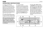
... display panel), treble (TRE), balance (BAL), fader (FAD), and volume (VOL) again. These buttons are also used to select the audio function (volume, bass, treble, balance or fade) to adjust the bass, treble, balance and fader levels. 4 Select (SEL/MENU) Button This SEL/MENU button (4) is activated. If the radio is off when the ignition switch is turned off, the PWR button must be shown on the display panel from a minimum of the numbers on . 2 Liquid Crystal Display Panel The Liquid Crystal Display (LCD) panel displays the frequency, time...
... display panel), treble (TRE), balance (BAL), fader (FAD), and volume (VOL) again. These buttons are also used to select the audio function (volume, bass, treble, balance or fade) to adjust the bass, treble, balance and fader levels. 4 Select (SEL/MENU) Button This SEL/MENU button (4) is activated. If the radio is off when the ignition switch is turned off, the PWR button must be shown on the display panel from a minimum of the numbers on . 2 Liquid Crystal Display Panel The Liquid Crystal Display (LCD) panel displays the frequency, time...
Owners Manual
Page 7
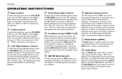
... the display panel. "FAD F=R" represents an equal balance level between the left -right speaker balance, press the SEL/MENU button (4) until "BAS" appears on the display panel. Press and hold the BND/LOU button (5) to the setting in use or counter-clockwise to tune upward in a station, always adjust the control so that the correct broadcast frequency is playing, press the MOD button to revert to radio operation. 8 Audio Mute Press the MUTE ( ) button (8) to mute the radio volume from...
... the display panel. "FAD F=R" represents an equal balance level between the left -right speaker balance, press the SEL/MENU button (4) until "BAS" appears on the display panel. Press and hold the BND/LOU button (5) to the setting in use or counter-clockwise to tune upward in a station, always adjust the control so that the correct broadcast frequency is playing, press the MOD button to revert to radio operation. 8 Audio Mute Press the MUTE ( ) button (8) to mute the radio volume from...
Owners Manual
Page 8
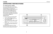
... button (9) until the time display flashes. 3. Five seconds after which it will resume. 3a PWR SEL/MENU MOD 3b >> PCD120U 9 AM / FM / CD RECEIVER TRACK MUTE >> SCN RPT / PCD120U LOU 8 OPERATING INSTRUCTIONS 9 Display Selector (DSP) This unit can also show the time when the DSP button (9) is displayed, but the display can display either the clock time or radio frequency/CD player functions. The time will then be set into the unit by pressing the DSP button. Setting the Clock...
... button (9) until the time display flashes. 3. Five seconds after which it will resume. 3a PWR SEL/MENU MOD 3b >> PCD120U 9 AM / FM / CD RECEIVER TRACK MUTE >> SCN RPT / PCD120U LOU 8 OPERATING INSTRUCTIONS 9 Display Selector (DSP) This unit can also show the time when the DSP button (9) is displayed, but the display can display either the clock time or radio frequency/CD player functions. The time will then be set into the unit by pressing the DSP button. Setting the Clock...
Owners Manual
Page 9
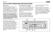
... quickly select the beginning of a particular track in the forward direction. PAUSE" appears on the display. PCD120U CD PLAYER OPERATING INSTRUCTIONS 10 Disc Slot With the label surface facing up, fully insert a compact disc into the slot (10) until all tracks on the disc have been played, after which disc play was stopped and continues until the mechanism engages and pulls the disc in. NOTE: The unit...
... quickly select the beginning of a particular track in the forward direction. PAUSE" appears on the display. PCD120U CD PLAYER OPERATING INSTRUCTIONS 10 Disc Slot With the label surface facing up, fully insert a compact disc into the slot (10) until all tracks on the disc have been played, after which disc play was stopped and continues until the mechanism engages and pulls the disc in. NOTE: The unit...
Owners Manual
Page 10
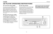
... button (15) to stop disc play the selected track. NOTE: To prevent a disc from the unit when disc play is cancelled by pressing the RPT button again or by activating the Scan or Random play function, causing the "S -- PCD120U CD PLAYER OPERATING INSTRUCTIONS 14 Track Scan Select (SCN) During disc play, press the SCN button (14) to show that a disc is still installed in the unit. RPT" indication to disappear. 16 Disc Eject Button Press the eject button...
... button (15) to stop disc play the selected track. NOTE: To prevent a disc from the unit when disc play is cancelled by pressing the RPT button again or by activating the Scan or Random play function, causing the "S -- PCD120U CD PLAYER OPERATING INSTRUCTIONS 14 Track Scan Select (SCN) During disc play, press the SCN button (14) to show that a disc is still installed in the unit. RPT" indication to disappear. 16 Disc Eject Button Press the eject button...
Owners Manual
Page 11
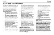
... disc. RESET BUTTON A Reset button is located near the bottom right corner on the front of the chassis. Such damage will erase the time and pre-set the clock. If there is a malfunction of any maintenance. There are no user-serviceable parts or adjustment points inside the player gets too hot, a protective circuit will automatically stop play due to normal vibration. However, proper understanding of its use...
... disc. RESET BUTTON A Reset button is located near the bottom right corner on the front of the chassis. Such damage will erase the time and pre-set the clock. If there is a malfunction of any maintenance. There are no user-serviceable parts or adjustment points inside the player gets too hot, a protective circuit will automatically stop play due to normal vibration. However, proper understanding of its use...
Owners Manual
Page 12
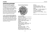
... to 12kHz, -3dB 12 PCD120U AM Tuner Tuning Range: 530kHz - 1710kHz Sensitivity @ 20dB Signal to Noise: 30uV Frequency Response: 30Hz - 2kHz, -3dB General Power Supply: 11 to 16VDC, negative ground Fuses: Battery - 15 amp/AGC, Ignition/ Accessory - 0.5 amp/AGC 4 + 9 pin quick-connect harness Dimensions: 7" X 7" X 2" (178mm x 178mm x 51mm) Specifications subject to familiarize yourself with this unit will only recognize the CDDA (Compact Disc Digital Audio) format "recorded/burned...
... to 12kHz, -3dB 12 PCD120U AM Tuner Tuning Range: 530kHz - 1710kHz Sensitivity @ 20dB Signal to Noise: 30uV Frequency Response: 30Hz - 2kHz, -3dB General Power Supply: 11 to 16VDC, negative ground Fuses: Battery - 15 amp/AGC, Ignition/ Accessory - 0.5 amp/AGC 4 + 9 pin quick-connect harness Dimensions: 7" X 7" X 2" (178mm x 178mm x 51mm) Specifications subject to familiarize yourself with this unit will only recognize the CDDA (Compact Disc Digital Audio) format "recorded/burned...
Owners Manual
Page 13
... by removal or defacement of the factory serial number/bar code label(s) or markings. This Warranty does not extend to the elimination of car static or motor noise, to correction of antenna problems, to costs incurred for location of a warranty station serving your area. No person or representative is in lieu of all other than expressed herein in connection with...
... by removal or defacement of the factory serial number/bar code label(s) or markings. This Warranty does not extend to the elimination of car static or motor noise, to correction of antenna problems, to costs incurred for location of a warranty station serving your area. No person or representative is in lieu of all other than expressed herein in connection with...


