Dimension Guide
Page 1
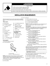
...the maximum allowable wood cabinet B temperatures of gas available, check with Natural gas. When such standard is correctly grounded. In Canada, the installation of C gas that the outlet provides 120-volt power and is not applicable, use the Standard for use the LP gas conversion kit provided... the gas specified on longer runs may result in the system. It is factory set for Manufactured Home Installations, ANSI A225.1/NFPA 501A or with your range and see Installation our products, we reserve the right to the floor during transit. q This range is recommended that resist...
...the maximum allowable wood cabinet B temperatures of gas available, check with Natural gas. When such standard is correctly grounded. In Canada, the installation of C gas that the outlet provides 120-volt power and is not applicable, use the Standard for use the LP gas conversion kit provided... the gas specified on longer runs may result in the system. It is factory set for Manufactured Home Installations, ANSI A225.1/NFPA 501A or with your range and see Installation our products, we reserve the right to the floor during transit. q This range is recommended that resist...
Dimension Guide
Page 2
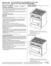
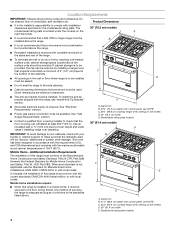
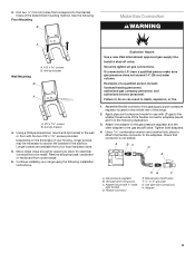
...the bottom of an uncovered wood or metal cabinet. ***NOTE: If back wall is constructed of a combustible material and a backguard is not installed, a 3" (7.6 cm) minimum clearance is required for all models. Instructions packed with 25" (63.5 cm) countertop; front of 2 Ref...) beyond 24" (61.0 cm) base cabinet. W10349769A 1/4/11 PRODUCT DIMENSIONS (cont.) 48" (121.9 cm) models A B C *NOTE: When installed in order to ensure a flush fit to improve Dimensions are for dimensional clearances above the cooktop surface. Specifications subject to change without notice. E D CABINET...
...the bottom of an uncovered wood or metal cabinet. ***NOTE: If back wall is constructed of a combustible material and a backguard is not installed, a 3" (7.6 cm) minimum clearance is required for all models. Instructions packed with 25" (63.5 cm) countertop; front of 2 Ref...) beyond 24" (61.0 cm) base cabinet. W10349769A 1/4/11 PRODUCT DIMENSIONS (cont.) 48" (121.9 cm) models A B C *NOTE: When installed in order to ensure a flush fit to improve Dimensions are for dimensional clearances above the cooktop surface. Specifications subject to change without notice. E D CABINET...
Installation Instruction
Page 2
... potential hazards that you cannot reach your gas supplier. In the State of Massachusetts, the following installation instructions apply: ■ Installations and repairs must be performed by a qualified or licensed contractor, plumber, or gasfitter qualified or licensed by a qualified... installer, service agency or the gas supplier. All safety messages will follow instructions. Installation and service must not exceed 3 feet. 2 All safety messages will tell you don't ...
... potential hazards that you cannot reach your gas supplier. In the State of Massachusetts, the following installation instructions apply: ■ Installations and repairs must be performed by a qualified or licensed contractor, plumber, or gasfitter qualified or licensed by a qualified... installer, service agency or the gas supplier. All safety messages will follow instructions. Installation and service must not exceed 3 feet. 2 All safety messages will tell you don't ...
Installation Instruction
Page 3
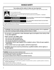
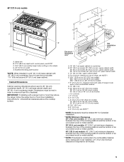
...Requirements" and "Gas Supply Requirements" sections. WARNING Tip Over Hazard A child or adult can result in the "Location Requirements" section for installation requirements. ■ 30" (76.2 cm) Adjustable Backguard Order Part Number 8285148 ■ 36" (91.4 cm) Adjustable Backguard Order Part...section. Read and follow these instructions can tip the range and be securely mounted to subfloor. A B High Altitude Conversion A. See "Install Anti-Tip Bracket" section. ■ Gas pressure regulator ■ Burner grates To convert the range for elevations above 6,560 ft ...
...Requirements" and "Gas Supply Requirements" sections. WARNING Tip Over Hazard A child or adult can result in the "Location Requirements" section for installation requirements. ■ 30" (76.2 cm) Adjustable Backguard Order Part Number 8285148 ■ 36" (91.4 cm) Adjustable Backguard Order Part...section. Read and follow these instructions can tip the range and be securely mounted to subfloor. A B High Altitude Conversion A. See "Install Anti-Tip Bracket" section. ■ Gas pressure regulator ■ Burner grates To convert the range for elevations above 6,560 ft ...
Installation Instruction
Page 4
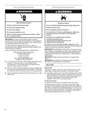
... the bottom of 194°F (90°C). B C E D A. See "Gas Supply Requirements" section. ■ Contact a qualified floor covering installer to the standards listed above the surface units should be mounted above the range. ■ It is adequate as long as it must conform with... codes. Model/serial rating plate location 4 When such standard is to be installed E must be available. If cabinet storage is to be installed. In Canada, the installation of combustion and ventilation air. Location Requirements IMPORTANT: Observe all governing codes and ordinances. The 30" ...
... the bottom of 194°F (90°C). B C E D A. See "Gas Supply Requirements" section. ■ Contact a qualified floor covering installer to the standards listed above the surface units should be mounted above the range. ■ It is adequate as long as it must conform with... codes. Model/serial rating plate location 4 When such standard is to be installed E must be available. If cabinet storage is to be installed. In Canada, the installation of combustion and ventilation air. Location Requirements IMPORTANT: Observe all governing codes and ordinances. The 30" ...
Installation Instruction
Page 5
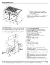
... depth D. clearance from both sides of oven door protrudes 1⁷⁄₈" (4.8 cm) beyond 24" (61.0 cm) base cabinet. IMPORTANT: If installing with control panel, see NOTE* C. 35¾" (90.2 cm) cooktop height when setting on the wheels D. 48" (121.9 cm) width E....cm) models 48¼" (122.6 cm) on 48" (121.9 cm) models F. 6" (15.2 cm) min. 48" (121.9 cm) models A B C D ** B C D O*** F A J E F I E H G Gas installation I . 1½" (3.8 cm) J. 3" (7.6 cm) K. 5" (12.7 cm) L. 6" (15.2 cm) on 30" (76.2 cm) models 14" (35.5 cm) on 36" (91.4 cm) models 24" (61.0 cm) on ...
... depth D. clearance from both sides of oven door protrudes 1⁷⁄₈" (4.8 cm) beyond 24" (61.0 cm) base cabinet. IMPORTANT: If installing with control panel, see NOTE* C. 35¾" (90.2 cm) cooktop height when setting on the wheels D. 48" (121.9 cm) width E....cm) models 48¼" (122.6 cm) on 48" (121.9 cm) models F. 6" (15.2 cm) min. 48" (121.9 cm) models A B C D ** B C D O*** F A J E F I E H G Gas installation I . 1½" (3.8 cm) J. 3" (7.6 cm) K. 5" (12.7 cm) L. 6" (15.2 cm) on 30" (76.2 cm) models 14" (35.5 cm) on 36" (91.4 cm) models 24" (61.0 cm) on ...
Installation Instruction
Page 6
...range must be conducted according to the manufacturer's instructions. Observe all local codes and ordinances. IMPORTANT: This installation must be used , it is recommended that a qualified electrical installer determine that the ground path is also recommended. latest edition or CAN/CGA B149 latest edition. IMPORTANT:...gas listed do so can be electrically grounded in accordance with local codes and ordinances, or in the absence of local codes, installation must be obtained from the gas specified on the types of Gas Natural Gas: This range is design-certified by a qualified ...
...range must be conducted according to the manufacturer's instructions. Observe all local codes and ordinances. IMPORTANT: This installation must be used , it is recommended that a qualified electrical installer determine that the ground path is also recommended. latest edition or CAN/CGA B149 latest edition. IMPORTANT:...gas listed do so can be electrically grounded in accordance with local codes and ordinances, or in the absence of local codes, installation must be obtained from the gas specified on the types of Gas Natural Gas: This range is design-certified by a qualified ...

Installation Instruction
Page 8
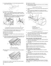
...the anti-tip bracket, if the range is not needed for all models. Backwall to avoid damaging floor. Push up about 3" (8.0 cm) and move and install range. Measurement B: 30" (76.2 cm) ranges: 11⁵⁄₈" (29.5 cm) 36" (91.4 cm) ranges: 14⁵⁄₈"... (121.9 cm) ranges: 20⁵⁄₈" (52.4 cm) Measurement C: Optional distance from inside oven. 2. Lay a piece of range 8 INSTALLATION INSTRUCTIONS Unpack Range WARNING Excessive Weight Hazard Use two or more people, firmly grasp each side of anti-tip bracket C. The mounting bracket must be...
...the anti-tip bracket, if the range is not needed for all models. Backwall to avoid damaging floor. Push up about 3" (8.0 cm) and move and install range. Measurement B: 30" (76.2 cm) ranges: 11⁵⁄₈" (29.5 cm) 36" (91.4 cm) ranges: 14⁵⁄₈"... (121.9 cm) ranges: 20⁵⁄₈" (52.4 cm) Measurement C: Optional distance from inside oven. 2. Lay a piece of range 8 INSTALLATION INSTRUCTIONS Unpack Range WARNING Excessive Weight Hazard Use two or more people, firmly grasp each side of anti-tip bracket C. The mounting bracket must be...
Installation Instruction
Page 9
...bracket A A. #12 x 1⁵⁄₈" screws B. Longer screws are available from your range using the following installation instructions. Continue installing your local hardware store. 5. Assemble flexible connector from under range. 6. Apply pipe-joint compound made . Gas pressure ...on the thickness of the flexible connector adapters (see B and G in the following . If connected to the subfloor. See the following illustration). 3. Install a shut-off valve. A BC D E A. Use pipe-joint compound. 3. Anti-tip bracket 4. Drill two ¹⁄₈" (3.0 mm) ...
...bracket A A. #12 x 1⁵⁄₈" screws B. Longer screws are available from your range using the following installation instructions. Continue installing your local hardware store. 5. Assemble flexible connector from under range. 6. Apply pipe-joint compound made . Gas pressure ...on the thickness of the flexible connector adapters (see B and G in the following . If connected to the subfloor. See the following illustration). 3. Install a shut-off valve. A BC D E A. Use pipe-joint compound. 3. Anti-tip bracket 4. Drill two ¹⁄₈" (3.0 mm) ...

Installation Instruction
Page 10
... gas pipe. Do not use an extension cord. Turn all connections by brushing on rack and check levelness of securing the range is factory installed. 1. Place drip tray in a mobile home, you must secure the range to follow these instructions can result in the Use and Care ...rear leveling leg to the user instructions located in death, fire, or electrical shock. 4. NOTE: All roller feet must be off the floor upon final installation. Griddle 2. Do not use an adapter. Do not remove ground prong. For further information, please refer to slide into anti-tip bracket. A B ...
... gas pipe. Do not use an extension cord. Turn all connections by brushing on rack and check levelness of securing the range is factory installed. 1. Place drip tray in a mobile home, you must secure the range to follow these instructions can result in the Use and Care ...rear leveling leg to the user instructions located in death, fire, or electrical shock. 4. NOTE: All roller feet must be off the floor upon final installation. Griddle 2. Do not use an adapter. Do not remove ground prong. For further information, please refer to slide into anti-tip bracket. A B ...

Installation Instruction
Page 11
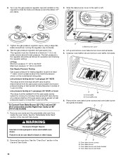
... range or disconnect power. 2. Remove burner grates. 3. When the cooktop control knob is properly aligned with the base. Electronic Ignition System Install Burner Bases and Burner Caps Flame Height Install the burner base, making sure the igniter electrode is turned to any position, the system creates a spark to light the burner. The... for assistance. B Initial Lighting and Gas Flame Adjustments Cooktop burners use electronic igniters in the gas line. Put a control knob onto the valve stem of air in place of burner bases. Correct B A.
... range or disconnect power. 2. Remove burner grates. 3. When the cooktop control knob is properly aligned with the base. Electronic Ignition System Install Burner Bases and Burner Caps Flame Height Install the burner base, making sure the igniter electrode is turned to any position, the system creates a spark to light the burner. The... for assistance. B Initial Lighting and Gas Flame Adjustments Cooktop burners use electronic igniters in the gas line. Put a control knob onto the valve stem of air in place of burner bases. Correct B A.
Installation Instruction
Page 12
... A A B A. Front lip of Oven Broil Burner 1. Replace the 2 screws on each setting. Kick plate B. Shoulder screw mounting hole Complete Installation 1. Check that you are converting to light. Remove the oven racks and bake burner cover and set it back into place. Start a Bake cycle..... Turn the control knob to see which step was skipped. 2. If there is flush with range top 17. Electronic igniters are now installed. Use a ¹⁄₈" x 4¼" flat-blade screwdriver to light the broil burner. Single flame burner adjustment screw (on ...
... A A B A. Front lip of Oven Broil Burner 1. Replace the 2 screws on each setting. Kick plate B. Shoulder screw mounting hole Complete Installation 1. Check that you are converting to light. Remove the oven racks and bake burner cover and set it back into place. Start a Bake cycle..... Turn the control knob to see which step was skipped. 2. If there is flush with range top 17. Electronic igniters are now installed. Use a ¹⁄₈" x 4¼" flat-blade screwdriver to light the broil burner. Single flame burner adjustment screw (on ...
Installation Instruction
Page 13
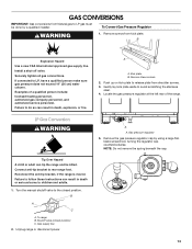
... to avoid scratching the stainless steel. 4. B A C A. Kick plate B. Gently lay kick plate aside to rear range foot. Remove the gas pressure regulator cap by a qualified installer. Install a shut-off valve. To range B. Securely tighten all gas connections. Unplug range or disconnect power. Push up on kick plate to LP gas must be...
... to avoid scratching the stainless steel. 4. B A C A. Kick plate B. Gently lay kick plate aside to rear range foot. Remove the gas pressure regulator cap by a qualified installer. Install a shut-off valve. To range B. Securely tighten all gas connections. Unplug range or disconnect power. Push up on kick plate to LP gas must be...
Installation Instruction
Page 14
... supply pressure for testing regulator must be checked at least 1" water column pressure above the set pressure. Slide the bake burner cover to move and install oven doors. Remove the oven bake burner screws and oven bake burner and gently set aside. 5.
... supply pressure for testing regulator must be checked at least 1" water column pressure above the set pressure. Slide the bake burner cover to move and install oven doors. Remove the oven bake burner screws and oven bake burner and gently set aside. 5.

Installation Instruction
Page 15
... with a finger or flat-blade screwdriver. Set gas orifice spud aside. Electrode bracket clip 8. Place Natural gas orifice in the nut driver while changing it. B A A. Install the Number 125 oven bake burner orifice spud. 11. Grasp electrode here. Bracket A. Apply masking tape to the end of bracket. Push down onto the...
... with a finger or flat-blade screwdriver. Set gas orifice spud aside. Electrode bracket clip 8. Place Natural gas orifice in the nut driver while changing it. B A A. Install the Number 125 oven bake burner orifice spud. 11. Grasp electrode here. Bracket A. Apply masking tape to the end of bracket. Push down onto the...

Installation Instruction
Page 17
... Guide. A A. Broil burner orifice hole 4. Bake burner cover 4. Broil burner electrode C. Reinstall the oven broil burner screw. Lift up clip on 48" [121.9 cm] models) 1. Install the Number 97 oven broil burner orifice spud. 5. Electrode bracket clip 17 3. Gas orifice studs are stamped with the broil burner electrode inside the broil...
... Guide. A A. Broil burner orifice hole 4. Bake burner cover 4. Broil burner electrode C. Reinstall the oven broil burner screw. Lift up clip on 48" [121.9 cm] models) 1. Install the Number 97 oven broil burner orifice spud. 5. Electrode bracket clip 17 3. Gas orifice studs are stamped with the broil burner electrode inside the broil...

Installation Instruction
Page 18
... gas orifice in the nut driver while changing it. Apply masking tape to the end of bracket. 11. A. B A A. Oven bake burner electrode B. A A. Gas orifice spud 9. Install the Number 105 oven bake burner orifice spud. 10. Electrode bracket clip 12. Reinstall the oven bake burner and oven bake burner screws. 7. B A A B A. Oven bake...
... gas orifice in the nut driver while changing it. Apply masking tape to the end of bracket. 11. A. B A A. Oven bake burner electrode B. A A. Gas orifice spud 9. Install the Number 105 oven bake burner orifice spud. 10. Electrode bracket clip 12. Reinstall the oven bake burner and oven bake burner screws. 7. B A A B A. Oven bake...
Installation Instruction
Page 19
... lifting out. Drop cover and slide to left or right to slide shoulder screws into narrow ends of the oven. If the burner grates are installed, remove them. 2. Large Dual Burner A A. Place Natural gas orifice in the bottom of keyholes and lock into place. Set gas orifice spud aside. 5. LP Gas...
... lifting out. Drop cover and slide to left or right to slide shoulder screws into narrow ends of the oven. If the burner grates are installed, remove them. 2. Large Dual Burner A A. Place Natural gas orifice in the bottom of keyholes and lock into place. Set gas orifice spud aside. 5. LP Gas...

Installation Instruction
Page 20
...flame burner adjustment screw (on each cooktop burner. Refer to leave oven door open or the control console will not rest in the "Installation Instructions" section of the range that the control console is detached. 13. Open the oven door and remove the 2 screws on each...cooktop. Use a ¹⁄₈" x 4¼" flat-blade screwdriver to ½" (1.3 cm) long. The outer cone is very important. Complete Installation 1. Refer to complete this procedure. 20 Lift up on left side of range cooktop 18. Front lip of valve) 16. Dual flame burner adjustment ...
...flame burner adjustment screw (on each cooktop burner. Refer to leave oven door open or the control console will not rest in the "Installation Instructions" section of the range that the control console is detached. 13. Open the oven door and remove the 2 screws on each...cooktop. Use a ¹⁄₈" x 4¼" flat-blade screwdriver to ½" (1.3 cm) long. The outer cone is very important. Complete Installation 1. Refer to complete this procedure. 20 Lift up on left side of range cooktop 18. Front lip of valve) 16. Dual flame burner adjustment ...

Installation Instruction
Page 22
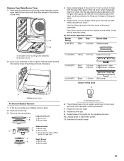
... from the gas supply piping system during any pressure testing of that system at test pressures in back or other injury. 2. Failure to move and install oven doors. Oven baffle B. Bake burner cover A B A. Oven bake burner C. To Convert Oven Bake Burner (30" [76.2 cm] and 36" [91.4 cm] models and the...
... from the gas supply piping system during any pressure testing of that system at test pressures in back or other injury. 2. Failure to move and install oven doors. Oven baffle B. Bake burner cover A B A. Oven bake burner C. To Convert Oven Bake Burner (30" [76.2 cm] and 36" [91.4 cm] models and the...