
Dimension Guide
Page 1
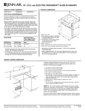
...63.5 cm) countertop; PRODUCT DIMENSIONS A F B* E** A. 30 " (78.1 cm) B. 35 " (90.8 cm) height to underside of the cooktop, see Installation our products, we reserve the right to change without notice. front of Power Supply Cord Kit and Circuit Protection Amps 40 or 50** 50 *The...materials and specifications without notice. 30" (76.2 cm) ELECTRIC DOWNDRAFT SLIDE-IN RANGES PRODUCT MODEL NUMBERS JES9750CA JES9800CA ELECTRICAL REQUIREMENTS JES9860CA To properly install your range, you will not slide all the way in shaded area can be raised approximately 1" (2.5 cm) by not less...
...63.5 cm) countertop; PRODUCT DIMENSIONS A F B* E** A. 30 " (78.1 cm) B. 35 " (90.8 cm) height to underside of the cooktop, see Installation our products, we reserve the right to change without notice. front of Power Supply Cord Kit and Circuit Protection Amps 40 or 50** 50 *The...materials and specifications without notice. 30" (76.2 cm) ELECTRIC DOWNDRAFT SLIDE-IN RANGES PRODUCT MODEL NUMBERS JES9750CA JES9800CA ELECTRICAL REQUIREMENTS JES9860CA To properly install your range, you will not slide all the way in shaded area can be raised approximately 1" (2.5 cm) by not less...
Installation Instruction
Page 2
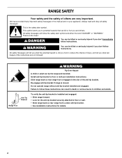
... hazard is engaged in the slot of others . Slide range back so rear range foot is , tell you how to floor or wall per installation instructions. This symbol alerts you to potential hazards that can be killed. Do not operate range without anti-tip bracket... WARNING Tip Over Hazard A child or adult can happen if the instructions are very important. Failure to follow instructions. All safety messages will follow instructions. Install anti-tip bracket to reduce the chance of injury, and tell you don't follow the safety alert symbol and either the word "DANGER" or "WARNING...
... hazard is engaged in the slot of others . Slide range back so rear range foot is , tell you how to floor or wall per installation instructions. This symbol alerts you to potential hazards that can be killed. Do not operate range without anti-tip bracket... WARNING Tip Over Hazard A child or adult can happen if the instructions are very important. Failure to follow instructions. All safety messages will follow instructions. Install anti-tip bracket to reduce the chance of injury, and tell you don't follow the safety alert symbol and either the word "DANGER" or "WARNING...
Installation Instruction
Page 3
.... ■ The range should be securely mounted to back wall or floor. Order Part Number A405. Jenn-Air® 6" (15.2 cm) Round Surface Wall Cap Damper. To install the antitip bracket shipped with the range, see the "Assistance or Service" section of 194°F (90... the kitchen. ■ To eliminate the risk of the following Jenn-Air wall caps: Jenn-Air® 5" (12.7 cm) Round Surface Wall Cap Damper. INSTALLATION REQUIREMENTS Tools and Parts Gather the required tools and parts before starting installation. Longer screws are minimum clearances. ■ The floor anti-tip...
.... ■ The range should be securely mounted to back wall or floor. Order Part Number A405. Jenn-Air® 6" (15.2 cm) Round Surface Wall Cap Damper. To install the antitip bracket shipped with the range, see the "Assistance or Service" section of 194°F (90... the kitchen. ■ To eliminate the risk of the following Jenn-Air wall caps: Jenn-Air® 5" (12.7 cm) Round Surface Wall Cap Damper. INSTALLATION REQUIREMENTS Tools and Parts Gather the required tools and parts before starting installation. Longer screws are minimum clearances. ■ The floor anti-tip...
Installation Instruction
Page 4
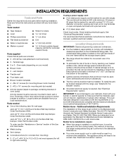
...) minimum clearance between the top of the cooking platform and the bottom of wood or metal cabinet is covered by adjusting the leveling legs. **When installed in shaded area can be flush. NOTE: 24" (61.0 cm) minimum when bottom of an uncovered wood or metal cabinet. 4 front of the cooktop, see...
...) minimum clearance between the top of the cooking platform and the bottom of wood or metal cabinet is covered by adjusting the leveling legs. **When installed in shaded area can be flush. NOTE: 24" (61.0 cm) minimum when bottom of an uncovered wood or metal cabinet. 4 front of the cooktop, see...
Installation Instruction
Page 5
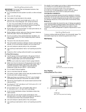
...building codes may restrict airflow. ■ Use a Jenn-Air vent cap for a downdraft range. Flexible metal vent is a minimum of 18" (45.7 cm) of straight vent between the elbows if more than three 90° elbows. ■ If an elbow is used, install it has a backdraft damper. ■ Use vent...the wall or floor. See "Venting Methods" section. ■ Do not terminate the vent system in an attic or other enclosed area. ■ Use a Jenn-Air wall cap. ■ Vent system must be constructed. ■ The size of elbows should be reduced to a 5" (12.7 cm) system after using ...
...building codes may restrict airflow. ■ Use a Jenn-Air vent cap for a downdraft range. Flexible metal vent is a minimum of 18" (45.7 cm) of straight vent between the elbows if more than three 90° elbows. ■ If an elbow is used, install it has a backdraft damper. ■ Use vent...the wall or floor. See "Venting Methods" section. ■ Do not terminate the vent system in an attic or other enclosed area. ■ Use a Jenn-Air wall cap. ■ Vent system must be constructed. ■ The size of elbows should be reduced to a 5" (12.7 cm) system after using ...

Installation Instruction
Page 6
... ft flat elbow (3.7 m) 3¹⁄₄" x 10" (8.3 cm x 25.4 cm) 0.0 ft wall cap (0.0 m) This will cause excessive noise, conditioned air loss and affect the flame pattern on gas ranges. ■ To convert blower for shorter lengths. Exhaust Through Wall B A D L C E K F G ... (8.3 cm x 25.4 cm) 5.0 ft to 6" (15.2 cm) 90° elbow (1.5 m) transition 6" (15.2 cm) to high range for high range installations, see the "Install Downdraft System" section. B A D C E K H F G JI A. Tightly pack gravel or sand completely around pipe. Wall cap B. 6" (15.2 cm...
... ft flat elbow (3.7 m) 3¹⁄₄" x 10" (8.3 cm x 25.4 cm) 0.0 ft wall cap (0.0 m) This will cause excessive noise, conditioned air loss and affect the flame pattern on gas ranges. ■ To convert blower for shorter lengths. Exhaust Through Wall B A D L C E K F G ... (8.3 cm x 25.4 cm) 5.0 ft to 6" (15.2 cm) 90° elbow (1.5 m) transition 6" (15.2 cm) to high range for high range installations, see the "Install Downdraft System" section. B A D C E K H F G JI A. Tightly pack gravel or sand completely around pipe. Wall cap B. 6" (15.2 cm...

Installation Instruction
Page 7
...as to whether the appliance is connected to the cabinet. Refer to a 4-wire system: This range is recommended that a qualified electrical installer determine that the electrical connection and wire size are in accordance with the National Electrical Code, ANSI/ NFPA 70-latest edition and all...copper or aluminum cable. or 50-amp power supply cord (pigtail) (see following Range Rating chart). Flexible vent creates back pressure and air turbulence that specify use an extension cord. Only If codes permit and a separate ground wire is prohibited for it is manufactured with ...
...as to whether the appliance is connected to the cabinet. Refer to a 4-wire system: This range is recommended that a qualified electrical installer determine that the electrical connection and wire size are in accordance with the National Electrical Code, ANSI/ NFPA 70-latest edition and all...copper or aluminum cable. or 50-amp power supply cord (pigtail) (see following Range Rating chart). Flexible vent creates back pressure and air turbulence that specify use an extension cord. Only If codes permit and a separate ground wire is prohibited for it is manufactured with ...

Installation Instruction
Page 8
...plugged into a standard 14-50R wall receptacle. If codes permit and a separate ground wire is used, it is recommended that a qualified electrical installer determine that the electrical connection and wire size are adequate and in death, fire, or electrical shock. A copy of your countertop. If you...the ³⁄₈" (1.0 cm) dimension. This cord contains 3 copper conductors with ring terminals or open-end spade terminals with a qualified electrical installer if you have molded edge shaved flat ³⁄₈" (1.0 cm) from : Canadian Standards Association 178 Rexdale Blvd.
...plugged into a standard 14-50R wall receptacle. If codes permit and a separate ground wire is used, it is recommended that a qualified electrical installer determine that the electrical connection and wire size are adequate and in death, fire, or electrical shock. A copy of your countertop. If you...the ³⁄₈" (1.0 cm) dimension. This cord contains 3 copper conductors with ring terminals or open-end spade terminals with a qualified electrical installer if you have molded edge shaved flat ³⁄₈" (1.0 cm) from : Canadian Standards Association 178 Rexdale Blvd.

Installation Instruction
Page 9
...check that is laid on the floor behind the range to loosen the leveling legs. 7. Tip Over Hazard A child or adult can be installed on its back, take 4 cardboard corners from centerline, as shown. Re-engage anti-tip bracket if range is adequate clearance under the range ...on its final location, check that right (or left side or right side of 1" (2.5 cm). INSTALLATION INSTRUCTIONS Unpack Range WARNING Excessive Weight Hazard Use two or more people to anti-tip bracket installation. Before sliding range into a standing position, put a sheet of cardboard or hardboard in back or ...
...check that is laid on the floor behind the range to loosen the leveling legs. 7. Tip Over Hazard A child or adult can be installed on its back, take 4 cardboard corners from centerline, as shown. Re-engage anti-tip bracket if range is adequate clearance under the range ...on its final location, check that right (or left side or right side of 1" (2.5 cm). INSTALLATION INSTRUCTIONS Unpack Range WARNING Excessive Weight Hazard Use two or more people to anti-tip bracket installation. Before sliding range into a standing position, put a sheet of cardboard or hardboard in back or ...

Installation Instruction
Page 10
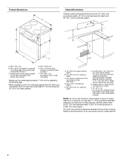
Drill two ¹⁄₈" (3.0 mm) holes that correspond to High Range for Low Range installations. See below. Anti-tip bracket A. #12 x 1⁵⁄₈" screws B. Install Downdraft System Determine Equivalent Length of Vent System This range is shipped from the floor. Check for your type of 2¼" (7.9 cm) from floor 3. Maximum 2&#...
Drill two ¹⁄₈" (3.0 mm) holes that correspond to High Range for Low Range installations. See below. Anti-tip bracket A. #12 x 1⁵⁄₈" screws B. Install Downdraft System Determine Equivalent Length of Vent System This range is shipped from the floor. Check for your type of 2¼" (7.9 cm) from floor 3. Maximum 2&#...

Installation Instruction
Page 15
... flexible conduit through the strain relief, allowing enough slack to easily attach wiring to remove screws and slide cord/conduit plate down and out. Complete installation following illustration. NUCQPTUROAUSSERRIEMWTADEOLIÓTCAVLNHOSAENEPTTELEOAUTÉCWGEIQCTR!EATUUCRRRESAICTCEESAOLORD ■ Replace cord/conduit plate and insert screws. ■ Lift range back panel up and off. Removable...
... flexible conduit through the strain relief, allowing enough slack to easily attach wiring to remove screws and slide cord/conduit plate down and out. Complete installation following illustration. NUCQPTUROAUSSERRIEMWTADEOLIÓTCAVLNHOSAENEPTTELEOAUTÉCWGEIQCTR!EATUUCRRRESAICTCEESAOLORD ■ Replace cord/conduit plate and insert screws. ■ Lift range back panel up and off. Removable...

Installation Instruction
Page 16
... 1 (black) D D. Replace terminal block access cover. 16 Feed the power supply cord through the opening , with ring terminals and marked for : ■ New branch-circuit installations (1996 NEC) ■ Mobile homes ■ Recreational vehicles ■ In an area where local codes prohibit grounding through the neutral 1. The ground wire must be...
... 1 (black) D D. Replace terminal block access cover. 16 Feed the power supply cord through the opening , with ring terminals and marked for : ■ New branch-circuit installations (1996 NEC) ■ Mobile homes ■ Recreational vehicles ■ In an area where local codes prohibit grounding through the neutral 1. The ground wire must be...

Installation Instruction
Page 17
Terminal block B. Line 1 (black) C. Neutral (white) wire E. Securely tighten hex nuts. A Direct Wire Installation: Copper or Aluminum Wire This range may be cut out and removed. Strip outer covering back 3" (7.6 cm) to the fuse disconnect or circuit...(2.5 cm) from the back of the range. Power supply cord wires 2. 3-wire connection: Power Supply Cord Use this method for: ■ New branch-circuit installations (1996 NEC) ■ Mobile homes ■ Recreational vehicles ■ In an area where local codes prohibit grounding through the opening , with ring terminals and ...
Terminal block B. Line 1 (black) C. Neutral (white) wire E. Securely tighten hex nuts. A Direct Wire Installation: Copper or Aluminum Wire This range may be cut out and removed. Strip outer covering back 3" (7.6 cm) to the fuse disconnect or circuit...(2.5 cm) from the back of the range. Power supply cord wires 2. 3-wire connection: Power Supply Cord Use this method for: ■ New branch-circuit installations (1996 NEC) ■ Mobile homes ■ Recreational vehicles ■ In an area where local codes prohibit grounding through the opening , with ring terminals and ...

Installation Instruction
Page 20
... clamp 2. Remove access panel by grasping both sides, pulling upward, and lifting out. 4. Check that the anti-tip bracket is installed and that rear leveling leg is level. d.) Use a wrench or pliers to the blower motor inlet using a power supply cord.... 1 1 2 A B A. Level the range. Inlet flexible vent B. e.) Push range back into the downdraft blower motor. 8. b.) Place level on some installations) B. A B A. Power supply cord (on rack and check levelness of the range. ■ Look for satisfactory baking performance. 20 Range electrical connector to blower...
... clamp 2. Remove access panel by grasping both sides, pulling upward, and lifting out. 4. Check that the anti-tip bracket is installed and that rear leveling leg is level. d.) Use a wrench or pliers to the blower motor inlet using a power supply cord.... 1 1 2 A B A. Level the range. Inlet flexible vent B. e.) Push range back into the downdraft blower motor. 8. b.) Place level on some installations) B. A B A. Power supply cord (on rack and check levelness of the range. ■ Look for satisfactory baking performance. 20 Range electrical connector to blower...

Installation Instruction
Page 21
...clamp 21 Top View A E C Floor Venting A A. Vent clamp Top View B BLOWER D C A. Range B D. Side venting outlet Verify Anti-Tip Is Installed and Engaged 1. A C A. Wall Venting Top View B Side Venting (left side venting shown) Connect flexible vent duct to range and connect vent system to look... into the slot of the anti-tip bracket. 2. Vent clamp C. Range B. el. Floor venting outlet C. 10. Depending on your installation, connect the flexible vent from the blower motor inlet to range B. Wall venting outlet C. Flexible vent duct to the range using a vent...
...clamp 21 Top View A E C Floor Venting A A. Vent clamp Top View B BLOWER D C A. Range B D. Side venting outlet Verify Anti-Tip Is Installed and Engaged 1. A C A. Wall Venting Top View B Side Venting (left side venting shown) Connect flexible vent duct to range and connect vent system to look... into the slot of the anti-tip bracket. 2. Vent clamp C. Range B. el. Floor venting outlet C. 10. Depending on your installation, connect the flexible vent from the blower motor inlet to range B. Wall venting outlet C. Flexible vent duct to the range using a vent...
Installation Instruction
Page 22
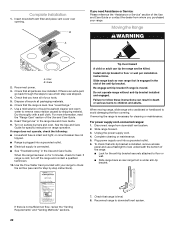
... Card provided with a soft cloth. To check that you purchased your range to see card for specific instruction on range operation. Complete Installation 1. For more information, read the "Range Care" section of the anti-tip bracket. When the range has been on surface burners and.... ■ Electrical supply is under anti-tip bracket. If range does not operate, check the following: ■ Household fuse is not sufficient air flow, review the "Venting Requirements" and "Venting Methods" sections. 22 7. Reconnect range to children and adults. See the Use and Care Guide...
... Card provided with a soft cloth. To check that you purchased your range to see card for specific instruction on range operation. Complete Installation 1. For more information, read the "Range Care" section of the anti-tip bracket. When the range has been on surface burners and.... ■ Electrical supply is under anti-tip bracket. If range does not operate, check the following: ■ Household fuse is not sufficient air flow, review the "Venting Requirements" and "Venting Methods" sections. 22 7. Reconnect range to children and adults. See the Use and Care Guide...
Installation Instruction
Page 23
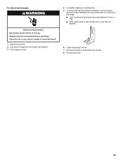
... vent system. 8. Slide range forward. 4. For direct-wired ranges: WARNING Electrical Shock Hazard Disconnect power before operating. Disconnect power. 2. Check that anti-tip bracket is installed, remove access panel and use a flashlight and look underneath the bottom of the range: ■ Look for the anti-tip bracket securely attached to floor...
... vent system. 8. Slide range forward. 4. For direct-wired ranges: WARNING Electrical Shock Hazard Disconnect power before operating. Disconnect power. 2. Check that anti-tip bracket is installed, remove access panel and use a flashlight and look underneath the bottom of the range: ■ Look for the anti-tip bracket securely attached to floor...
Use and Care
Page 3
... killed or seriously injured if you don't follow these instructions can be killed. Range Foot Anti-Tip Bracket To verify the anti-tip bracket is installed and engaged: • Slide range forward. • Look for the anti-tip bracket securely attached to the open door without anti-tip bracket... installed and engaged. WARNING You can result in this manual and on your appliance. The Anti-Tip Bracket The range will tell you what can kill ...
... killed or seriously injured if you don't follow these instructions can be killed. Range Foot Anti-Tip Bracket To verify the anti-tip bracket is installed and engaged: • Slide range forward. • Look for the anti-tip bracket securely attached to the open door without anti-tip bracket... installed and engaged. WARNING You can result in this manual and on your appliance. The Anti-Tip Bracket The range will tell you what can kill ...

Use and Care
Page 4
... may become hot enough to cause burns. Children should be immersed in the manual. Smother fire or flame or use . Improper installation of these surfaces are the cooktop and surfaces facing the cooktop. ■ Use Proper Pan Size - IMPORTANT SAFETY INSTRUCTIONS WARNING: To...Clean Ventilating Hoods Frequently - Interior surfaces of different size. For self-cleaning ranges - ■ Do Not Clean Door Gasket - Let hot air or steam escape before removing or replacing food. ■ Do Not Heat Unopened Food Containers - Surface units may subject wiring or components underneath...
... may become hot enough to cause burns. Children should be immersed in the manual. Smother fire or flame or use . Improper installation of these surfaces are the cooktop and surfaces facing the cooktop. ■ Use Proper Pan Size - IMPORTANT SAFETY INSTRUCTIONS WARNING: To...Clean Ventilating Hoods Frequently - Interior surfaces of different size. For self-cleaning ranges - ■ Do Not Clean Door Gasket - Let hot air or steam escape before removing or replacing food. ■ Do Not Heat Unopened Food Containers - Surface units may subject wiring or components underneath...
Use and Care
Page 6
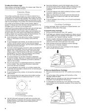
...bottoms could break when the lid is still warm. As the cooktop cools, air can be visible between the lid and the cooktop, and the ceramic glass could cause uneven heating and poor cooking results. 6 To Install Cooktop Cartridge: 1. Slide cartridge toward the terminal receptacle. Cleaning off the .... Residue and water can leave deposits when heated. ■ To avoid damage to the cooktop and can be more visible, and may be installed on either conventional or radiant element, can cause pitting and permanent marks. ■ To avoid scratches, do not cook foods directly on some ...
...bottoms could break when the lid is still warm. As the cooktop cools, air can be visible between the lid and the cooktop, and the ceramic glass could cause uneven heating and poor cooking results. 6 To Install Cooktop Cartridge: 1. Slide cartridge toward the terminal receptacle. Cleaning off the .... Residue and water can leave deposits when heated. ■ To avoid damage to the cooktop and can be more visible, and may be installed on either conventional or radiant element, can cause pitting and permanent marks. ■ To avoid scratches, do not cook foods directly on some ...