Instruction Manual
Page 1
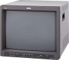
...modèle : Serial No. : Numéro de série : TM-H1950CG CHROMA CONTRAST VOLUME/SELECT PHASE BRIGHT MENU UNDER COLOR BLUE SCAN OFF CHECK ASPECT A B C SLOT D INPUT SELECT POWER (TM-H1950CG shown) (Gezeigtes Modell ist TM-H1950CG) (TM-H1950CG montré) (Modello TM-H1950CG) (Muestra de TM...DEUTSCH ENGLISH COLOR VIDEO MONITOR BEDIENUNGSANLEITUNG : FARB-VIDEO-MONITOR MANUEL D'INSTRUCTIONS : MONITEUR VIDÉO COULEUR MANUALE DI ISTRUZIONI : MONITOR VIDEO A COLORI INSTRUCCIONES : MONITOR DE VIDEO A COLOR !"#$%&'(&) TM-H1950CG TM-H1750CG INSTRUCTIONS For Customer Use: Enter...
...modèle : Serial No. : Numéro de série : TM-H1950CG CHROMA CONTRAST VOLUME/SELECT PHASE BRIGHT MENU UNDER COLOR BLUE SCAN OFF CHECK ASPECT A B C SLOT D INPUT SELECT POWER (TM-H1950CG shown) (Gezeigtes Modell ist TM-H1950CG) (TM-H1950CG montré) (Modello TM-H1950CG) (Muestra de TM...DEUTSCH ENGLISH COLOR VIDEO MONITOR BEDIENUNGSANLEITUNG : FARB-VIDEO-MONITOR MANUEL D'INSTRUCTIONS : MONITEUR VIDÉO COULEUR MANUALE DI ISTRUZIONI : MONITOR VIDEO A COLORI INSTRUCCIONES : MONITOR DE VIDEO A COLOR !"#$%&'(&) TM-H1950CG TM-H1750CG INSTRUCTIONS For Customer Use: Enter...

Instruction Manual
Page 2
ENGLISH INSTRUCTIONS COLOR VIDEO MONITOR TM-H1950CG TM-H1750CG Thank you for purchasing this JVC color video monitor. Before using it, read and follow all instructions carefully to take full advantage of the monitor's capabilities.
ENGLISH INSTRUCTIONS COLOR VIDEO MONITOR TM-H1950CG TM-H1750CG Thank you for purchasing this JVC color video monitor. Before using it, read and follow all instructions carefully to take full advantage of the monitor's capabilities.
Instruction Manual
Page 3
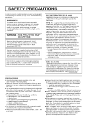
... of the cabinet. This monitor is no longer be regulated in your local authorities, or the Electronics Industries Alliance: PRECAUTIONS ● Use only the power source specified on the power cord. However, there is equipped with the instructions, may be operated. Connect the equipment into the unit, - only) CAUTION: Changes or modification not approved by turning the equipment off and...
... of the cabinet. This monitor is no longer be regulated in your local authorities, or the Electronics Industries Alliance: PRECAUTIONS ● Use only the power source specified on the power cord. However, there is equipped with the instructions, may be operated. Connect the equipment into the unit, - only) CAUTION: Changes or modification not approved by turning the equipment off and...
Instruction Manual
Page 4
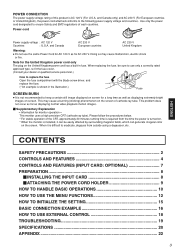
... (INPUT CARD: OPTIONAL 7 PREPARATION 8 Ⅵ INSTALLING THE INPUT CARD 8 Ⅵ ATTACHING THE POWER CORD HOLDER 9 HOW TO HANDLE BASIC OPERATIONS 10 HOW TO USE THE MENU FUNCTIONS 12 HOW TO INITIALIZE THE SETTING 15 BASIC CONNECTION EXAMPLE 16 HOW TO USE EXTERNAL CONTROL 18 TROUBLESHOOTING 19 SPECIFICATIONS 20 APPENDIX ...22 3 and Canada only) and AC 230 V (For European countries or United Kingdom), the power cord attached...
... (INPUT CARD: OPTIONAL 7 PREPARATION 8 Ⅵ INSTALLING THE INPUT CARD 8 Ⅵ ATTACHING THE POWER CORD HOLDER 9 HOW TO HANDLE BASIC OPERATIONS 10 HOW TO USE THE MENU FUNCTIONS 12 HOW TO INITIALIZE THE SETTING 15 BASIC CONNECTION EXAMPLE 16 HOW TO USE EXTERNAL CONTROL 18 TROUBLESHOOTING 19 SPECIFICATIONS 20 APPENDIX ...22 3 and Canada only) and AC 230 V (For European countries or United Kingdom), the power cord attached...

Instruction Manual
Page 5
...-DIN 4-pin connector). Green : The main power is ON, and the monitor's power is ON. Each time you press the button, the adjustment item changes. The button lights when selected. 11 Input B (VIDEO Y/C) button [INPUT SELECT B] Selects the video and audio signals input to turn the monitor's power ON or OFF when the main power is ON (in the menu function mode. 4 Volume/Select buttons [VOLUME/SELECT - +] Adjusts the speaker volume. The button lights when selected...
...-DIN 4-pin connector). Green : The main power is ON, and the monitor's power is ON. Each time you press the button, the adjustment item changes. The button lights when selected. 11 Input B (VIDEO Y/C) button [INPUT SELECT B] Selects the video and audio signals input to turn the monitor's power ON or OFF when the main power is ON (in the menu function mode. 4 Volume/Select buttons [VOLUME/SELECT - +] Adjusts the speaker volume. The button lights when selected...
Instruction Manual
Page 6
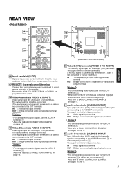
... a cable is bridge-connected. The output terminal is not connected to the OUT terminal.) IN : Y/C-separated (S-video) video signal input terminal OUT : Bridge-connected Y/C-separated (S-video) signal output terminal. IN : Audio signal input terminal OUT : Bridge-connected audio signal output terminal Notes: * For corresponding video signals, use the AUDIO B terminals w. * When both VIDEO B terminals are not provided when you purchase this monitor. 17 REMOTE (external control) terminal Connect this slot. Input cards are connected (input...
... a cable is bridge-connected. The output terminal is not connected to the OUT terminal.) IN : Y/C-separated (S-video) video signal input terminal OUT : Bridge-connected Y/C-separated (S-video) signal output terminal. IN : Audio signal input terminal OUT : Bridge-connected audio signal output terminal Notes: * For corresponding video signals, use the AUDIO B terminals w. * When both VIDEO B terminals are not provided when you purchase this monitor. 17 REMOTE (external control) terminal Connect this slot. Input cards are connected (input...
Instruction Manual
Page 7
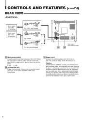
... Power cord Connects the provided power cord (120 V AC or 230 V AC, 50 Hz/60 Hz) to turn the main power ON or OFF. In Europe and the United Kingdom, two power cables are provided (one power cable. Caution: In North America (USA and Canada), this monitor comes with one for use the power cable that is appropriate for the UK). Be sure to use in orange and...
... Power cord Connects the provided power cord (120 V AC or 230 V AC, 50 Hz/60 Hz) to turn the main power ON or OFF. In Europe and the United Kingdom, two power cables are provided (one power cable. Caution: In North America (USA and Canada), this monitor comes with one for use the power cable that is appropriate for the UK). Be sure to use in orange and...

Instruction Manual
Page 8
... digital signals Input terminals for component (color deference) or RGB signals. Using any of these cards will void your warranty and may result in the input digital signal. 4 Connection terminal (to a Color Video Monitor) Attach to the connection terminal of your color video monitor. NOTE: When the monitor's main power is OFF, no cable is connected to SDI 1 and SDI 2. Select SDI 1 : press INPUT SELECT C button Select SDI 2 : press INPUT SELECT D button 3 Audio...
... digital signals Input terminals for component (color deference) or RGB signals. Using any of these cards will void your warranty and may result in the input digital signal. 4 Connection terminal (to a Color Video Monitor) Attach to the connection terminal of your color video monitor. NOTE: When the monitor's main power is OFF, no cable is connected to SDI 1 and SDI 2. Select SDI 1 : press INPUT SELECT C button Select SDI 2 : press INPUT SELECT D button 3 Audio...
Instruction Manual
Page 9
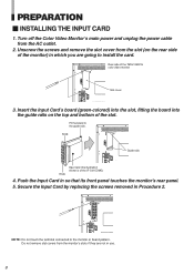
... Input Card by replacing the screws removed in so that its front panel touches the monitor's rear panel. 5. Turn off the Color Video Monitor's main power and unplug the power cable from the monitor's slots if they are going to install the card. Knob REMOTE SLOT VIDEO A IN VIDEO B IN IN OUT OUT Y/C Guide rails Knob Input card (the illustration shown is of the TM-H1950CG color video monitor SLOT REMOTE VIDEO A IN VIDEO B IN...
... Input Card by replacing the screws removed in so that its front panel touches the monitor's rear panel. 5. Turn off the Color Video Monitor's main power and unplug the power cable from the monitor's slots if they are going to install the card. Knob REMOTE SLOT VIDEO A IN VIDEO B IN IN OUT OUT Y/C Guide rails Knob Input card (the illustration shown is of the TM-H1950CG color video monitor SLOT REMOTE VIDEO A IN VIDEO B IN...
Instruction Manual
Page 11
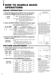
...; With the COLOR SYSTEM setting set UPPER or LOWER with the VOLUME/SELECT buttons. OFF : Power turns OFF. (Power indicator: unlit) Orange : The main power is ON, but the monitor's power is OFF (in the NTSC color system mode. ● Chroma control is not effective when receiving RGB and B/W or when no item is shown on screen, set to AUTO mode, when you want to "-40," the picture becomes less colorful. ●...
...; With the COLOR SYSTEM setting set UPPER or LOWER with the VOLUME/SELECT buttons. OFF : Power turns OFF. (Power indicator: unlit) Orange : The main power is ON, but the monitor's power is OFF (in the NTSC color system mode. ● Chroma control is not effective when receiving RGB and B/W or when no item is shown on screen, set to AUTO mode, when you want to "-40," the picture becomes less colorful. ●...

Instruction Manual
Page 12
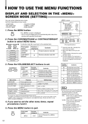
... CHECK button is pressed, the red and green signals are cut and only the blue signal is input. [Procedure] 1. Select COMPO. Input the standard color-bar signal for the adjustment so that the blue bars on the left and right sides of the screen have the same brightness. 5. (Only when an NTSC signal is input) Repeat procedures 3 and 4 for video signal control...
... CHECK button is pressed, the red and green signals are cut and only the blue signal is input. [Procedure] 1. Select COMPO. Input the standard color-bar signal for the adjustment so that the blue bars on the left and right sides of the screen have the same brightness. 5. (Only when an NTSC signal is input) Repeat procedures 3 and 4 for video signal control...
Instruction Manual
Page 13
... to set the following menu items. screen Set them depending on multiple ColorVideo Monitors simultaneously, it to quit. LEVEL* RUSH DELAY Purpose Picture aperture level Volume bar position Color temperature of the entire system. 12 STD. : Power turns on -screen display goes off automatically after the power switch is displayed only with component serial digital (SDI) input. (Shown with operation performed. 2. MENU Front panel button MENU Function displayed EXIT...
... to set the following menu items. screen Set them depending on multiple ColorVideo Monitors simultaneously, it to quit. LEVEL* RUSH DELAY Purpose Picture aperture level Volume bar position Color temperature of the entire system. 12 STD. : Power turns on -screen display goes off automatically after the power switch is displayed only with component serial digital (SDI) input. (Shown with operation performed. 2. MENU Front panel button MENU Function displayed EXIT...

Instruction Manual
Page 14
... the setting value. 1 Reverse the setting value. POSITION : 00 WHITE BALANCE CONTROL LOCK : OFF STATUS DISPLAY : ON REMOTE SYSTEM : MAKE INPUT REMOTE : A-D 2 3 EXIT 4 advance. ● WHITE BALANCE can set the following set-up menu items. screen • PICTURE SUB ADJ. • H. PHASE BRIGHT 1. Press the VOLUME/SELECT buttons to MAKE. Adjusts red and blue RB signal level. POSITION WHITE BALANCE CONTROL LOCK STATUS DISPLAY REMOTE SYSTEM INPUT REMOTE A selection...
... the setting value. 1 Reverse the setting value. POSITION : 00 WHITE BALANCE CONTROL LOCK : OFF STATUS DISPLAY : ON REMOTE SYSTEM : MAKE INPUT REMOTE : A-D 2 3 EXIT 4 advance. ● WHITE BALANCE can set the following set-up menu items. screen • PICTURE SUB ADJ. • H. PHASE BRIGHT 1. Press the VOLUME/SELECT buttons to MAKE. Adjusts red and blue RB signal level. POSITION WHITE BALANCE CONTROL LOCK STATUS DISPLAY REMOTE SYSTEM INPUT REMOTE A selection...

Instruction Manual
Page 15
... on screen for more information. ● When REMOTE SYSTEM is pressed, "REMOTE ON!" Trigger system: Controls the function by short-circuiting (shortcircuits or opens 15th terminal (GND)) with the VOLUME/ SELECT buttons - Adjusts red cut off . Select the function display for more details. 4. Power Switch operation - POSITION WHITE BALANCE DRIVE R. Selects the drive (DRV) or cut off (CUTO) adjustment. OFF ON Sets...
... on screen for more information. ● When REMOTE SYSTEM is pressed, "REMOTE ON!" Trigger system: Controls the function by short-circuiting (shortcircuits or opens 15th terminal (GND)) with the VOLUME/ SELECT buttons - Adjusts red cut off . Select the function display for more details. 4. Power Switch operation - POSITION WHITE BALANCE DRIVE R. Selects the drive (DRV) or cut off (CUTO) adjustment. OFF ON Sets...

Instruction Manual
Page 16
... 00 VOLUME 20 Volume Picture adjustment 15 Setting ⅷ Initialization is not required. Initial settings screen Sorts screen Functions (Items) Initialization (setting) APERTURE ADJ. LEVEL RUSH DELAY 00 LOWER 6500 AUTO 00 STD. CUT OFF 00 R. Press the Power ( ) switch to turn the power OFF (activate the standby mode). Keep pressing them until the display screen appears. 3. PICTURE SUB ADJ. POWER RESET screen RESET Are you sure ? While pressing both MENU button and...
... 00 VOLUME 20 Volume Picture adjustment 15 Setting ⅷ Initialization is not required. Initial settings screen Sorts screen Functions (Items) Initialization (setting) APERTURE ADJ. LEVEL RUSH DELAY 00 LOWER 6500 AUTO 00 STD. CUT OFF 00 R. Press the Power ( ) switch to turn the power OFF (activate the standby mode). Keep pressing them until the display screen appears. 3. PICTURE SUB ADJ. POWER RESET screen RESET Are you sure ? While pressing both MENU button and...

Instruction Manual
Page 17
... AUDIO B IN OUT OUT Audio (Audio signal cable) Audio (Audio signal cable) Video Monitor Video Camera Video (Video signal cable) VCR Video Monitor Audio (Audio signal cable) VCR : Signal Flow Video Monitor 16 When both terminals are turned off. • The illustration below shows some examples of input (IN) and output (OUT) terminals are bridge-connected. • If you are connecting. • Each pair of different connections. BASIC CONNECTION EXAMPLE Notes: • Before connecting your system, make sure that all units are connected...
... AUDIO B IN OUT OUT Audio (Audio signal cable) Audio (Audio signal cable) Video Monitor Video Camera Video (Video signal cable) VCR Video Monitor Audio (Audio signal cable) VCR : Signal Flow Video Monitor 16 When both terminals are turned off. • The illustration below shows some examples of input (IN) and output (OUT) terminals are bridge-connected. • If you are connecting. • Each pair of different connections. BASIC CONNECTION EXAMPLE Notes: • Before connecting your system, make sure that all units are connected...
Instruction Manual
Page 19
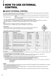
... stays ON while pressed. 18 Not change Change 6 not used - - - 7 not used should not be connected. *4 : Do not connect. *5 : Setting REMOTE ENABLE to A/B, pins not used - - - 8 COLOR OFF Changes the picture black-and-white. OFF : INPUT A ON : INPUT B NOTES : * When more than two terminals are disabled. is selected. * The 1st pin (TALLY) is set -up menu. • 4-pin control: Switches input by the setting of the D-sub connector. Note...
... stays ON while pressed. 18 Not change Change 6 not used - - - 7 not used should not be connected. *4 : Do not connect. *5 : Setting REMOTE ENABLE to A/B, pins not used - - - 8 COLOR OFF Changes the picture black-and-white. OFF : INPUT A ON : INPUT B NOTES : * When more than two terminals are disabled. is selected. * The 1st pin (TALLY) is set -up menu. • 4-pin control: Switches input by the setting of the D-sub connector. Note...

Instruction Manual
Page 20
.... Select the required video signal input with the ASPECT button on the screen as a white cloth) is displayed. ● You experience a mild electric shock when you touch the picture tube. Press the UNDER SCAN button to turn the monitor's power off the button. (See page 4.) Set CONTROL LOCK in the screen to AUTO. (See page 12.) Set each other until the picture stabilizes. No sound. This phenomenon is...
.... Select the required video signal input with the ASPECT button on the screen as a white cloth) is displayed. ● You experience a mild electric shock when you touch the picture tube. Press the UNDER SCAN button to turn the monitor's power off the button. (See page 4.) Set CONTROL LOCK in the screen to AUTO. (See page 12.) Set each other until the picture stabilizes. No sound. This phenomenon is...

Instruction Manual
Page 21
SPECIFICATIONS MODEL Type Color system Picture tube Effective screen size Scanning frequency Horizontal resolution Input terminals VIDEO A VIDEO B AUDIO A AUDIO B REMOTE Audio power output Built-in speaker Environmental conditions Power requirements Power consumption Dimensions Weight Accessory TM-H1950CG TM-H1750CG Color video monitor PAL, NTSC (3.58)... kg (56.3 lbs) (not including input card) 20.1 kg (44.3 lbs) (not including input card) AC power cord POWER CORD HOLDER x 1 (case and cover) Screw x 2 (POWER CORD HOLDER) * Illustrations used in -line gun, trio-dot type (phosphor...
SPECIFICATIONS MODEL Type Color system Picture tube Effective screen size Scanning frequency Horizontal resolution Input terminals VIDEO A VIDEO B AUDIO A AUDIO B REMOTE Audio power output Built-in speaker Environmental conditions Power requirements Power consumption Dimensions Weight Accessory TM-H1950CG TM-H1750CG Color video monitor PAL, NTSC (3.58)... kg (56.3 lbs) (not including input card) 20.1 kg (44.3 lbs) (not including input card) AC power cord POWER CORD HOLDER x 1 (case and cover) Screw x 2 (POWER CORD HOLDER) * Illustrations used in -line gun, trio-dot type (phosphor...

Instruction Manual
Page 23
Ⅵ Y/C (Mini DIN 4 pin) terminal specification 2 IN 1 OUT 2 1 4 3 Y/C 4 3 Pin No. 1 2 3 4 Signal GND (Y) GND (C) Y C APPENDIX: CONNECTION EXAMPLES FOR THE SDI INPUT CARD ● To use the front panel buttons or do it via external control. ● When INPUT-A or INPUT-B is selected, this connector outputs relocked digital signals.) ● Signal output from the SDI 1 connector are output. 22 21 You can be changed by selecting...
Ⅵ Y/C (Mini DIN 4 pin) terminal specification 2 IN 1 OUT 2 1 4 3 Y/C 4 3 Pin No. 1 2 3 4 Signal GND (Y) GND (C) Y C APPENDIX: CONNECTION EXAMPLES FOR THE SDI INPUT CARD ● To use the front panel buttons or do it via external control. ● When INPUT-A or INPUT-B is selected, this connector outputs relocked digital signals.) ● Signal output from the SDI 1 connector are output. 22 21 You can be changed by selecting...


