
Instructions
Page 3
... Monitor's Button Operations ...... 26 • Setting the Remote-Controllable Input 27 • Setting the High-Definition Signal Types 27 • Setting the Clock and the Power On/Off Timer 28 • Using the Pixel Shift Function 29 • Using the Power Save Function 29 • Preventing the Afterimage Effect 30 • Refreshing the Screen 31 • Checking the Timer Battery 32 • Resetting All the Setup Menu Settings 33 • Resetting All the Menu Settings...
... Monitor's Button Operations ...... 26 • Setting the Remote-Controllable Input 27 • Setting the High-Definition Signal Types 27 • Setting the Clock and the Power On/Off Timer 28 • Using the Pixel Shift Function 29 • Using the Power Save Function 29 • Preventing the Afterimage Effect 30 • Refreshing the Screen 31 • Checking the Timer Battery 32 • Resetting All the Setup Menu Settings 33 • Resetting All the Menu Settings...

Instructions
Page 5
... operating instructions. Use only the power cord designated to normal operation. These ensure reliable operation of the grounded plug. - These openings must not be blocked or covered. (The openings should be routed so that could result in a fire or electric shock. This product is damaged. This plug will often require extensive work by following power supply voltage and countries. If you need for...
... operating instructions. Use only the power cord designated to normal operation. These ensure reliable operation of the grounded plug. - These openings must not be blocked or covered. (The openings should be routed so that could result in a fire or electric shock. This product is damaged. This plug will often require extensive work by following power supply voltage and countries. If you need for...
Instructions
Page 6
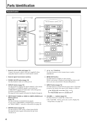
... Setup Menu (see page 22). Pressing the button again will make adjustments. 2 Remote signal transmission window 3 POWER ON/OFF button (page 14) Use this button to turn off the power. 8 MENU/EXIT button Use this button will resume the previous volume level. 4 To select the COMPONENT or RGB B input, you one screen back to the preceding menu. 4 DISPLAY button (page 14) Use this button to display the input terminal, color system (for VIDEO A or VIDEO B input), scan system (for COMPONENT input) and horizontal/vertical frequency (for RGB A and RGB B input...
... Setup Menu (see page 22). Pressing the button again will make adjustments. 2 Remote signal transmission window 3 POWER ON/OFF button (page 14) Use this button to turn off the power. 8 MENU/EXIT button Use this button will resume the previous volume level. 4 To select the COMPONENT or RGB B input, you one screen back to the preceding menu. 4 DISPLAY button (page 14) Use this button to display the input terminal, color system (for VIDEO A or VIDEO B input), scan system (for COMPONENT input) and horizontal/vertical frequency (for RGB A and RGB B input...

Instructions
Page 7
... remote control toward here. correctly on , the power lamp glows green. To select the COMPONENT or RGB B input, you can use the 2 / 3 buttons to adjust the volume level. 4 MENU button Use this button to set "RGB/COMPO." When the Monitor is displayed, you have to display or erase menus. It glows orange in standby mode. 2 Self-diagnostic lamps (page 39) These lamps light/flash if something abnormal occurs with the Monitor. 3 2 / 3 / 5 / ∞ buttons Use these buttons...
... remote control toward here. correctly on , the power lamp glows green. To select the COMPONENT or RGB B input, you can use the 2 / 3 buttons to adjust the volume level. 4 MENU button Use this button to set "RGB/COMPO." When the Monitor is displayed, you have to display or erase menus. It glows orange in standby mode. 2 Self-diagnostic lamps (page 39) These lamps light/flash if something abnormal occurs with the Monitor. 3 2 / 3 / 5 / ∞ buttons Use these buttons...

Instructions
Page 11
.../16) 100 (3 15/16) MENU INPUT POWER 50 (2) Unit: mm (inch) Notes: • Do not allow the same image (pattern) to the manual supplied for the stand. When mounting the Monitor on a particular case. For detailed information, refer to be within the range of pixels may be deficient or lit at all times. • Do not install the Monitor in brightness, leaving an afterimage on...
.../16) 100 (3 15/16) MENU INPUT POWER 50 (2) Unit: mm (inch) Notes: • Do not allow the same image (pattern) to the manual supplied for the stand. When mounting the Monitor on a particular case. For detailed information, refer to be within the range of pixels may be deficient or lit at all times. • Do not install the Monitor in brightness, leaving an afterimage on...

Instructions
Page 12
... vertical frequency displayed on the screen will have an "*" shown at its plug and pull it out. • Connect the power cord after having finished all other connections. • Refer also to the user manual of each piece of the following signals can be firmly inserted; on the remote control or from the "FUNCTION SELECT" menu (page 21). • When No. 8 to the RGB input terminals. Available Signals Video signals...
... vertical frequency displayed on the screen will have an "*" shown at its plug and pull it out. • Connect the power cord after having finished all other connections. • Refer also to the user manual of each piece of the following signals can be firmly inserted; on the remote control or from the "FUNCTION SELECT" menu (page 21). • When No. 8 to the RGB input terminals. Available Signals Video signals...

Instructions
Page 13
... ( speaker cords each other. (Refer also to the instructions supplied with stereo mini jacks (not supplied) Power cord (supplied) ❊ To a wall outlet Ferrite core (supplied to GM-V42UG) • Make sure to attach the ferrite core to the power cord. Amplifier, etc. TS-C421SPG) ·ª ·ª To speaker input terminals How to connect the cords To speaker input terminals When using external speakers, set this to control the Monitor) MENU/EXIT Remote control (supplied) ❊ For connection, see...
... ( speaker cords each other. (Refer also to the instructions supplied with stereo mini jacks (not supplied) Power cord (supplied) ❊ To a wall outlet Ferrite core (supplied to GM-V42UG) • Make sure to attach the ferrite core to the power cord. Amplifier, etc. TS-C421SPG) ·ª ·ª To speaker input terminals How to connect the cords To speaker input terminals When using external speakers, set this to control the Monitor) MENU/EXIT Remote control (supplied) ❊ For connection, see...

Instructions
Page 21
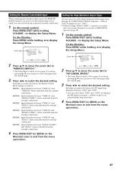
... Setup Menu consists of the color temperature. 1 On the remote control: Press MENU/EXIT while holding 2 to display the Main Menu. SYNC TERM. Note: • To make an adjustment. Cursor (3) SET-UP MENU STATUS DISPLAY CONTROL LOCK REMOTE SWITCH HD SIGNAL MODE WHITE BALANCE TIMER 1/2 : OFF : OFF : MODE1 : 1080i ADJUST: SELECT: EXIT: MENU 2 Press 5/∞ to move to the other items. 7 Press MENU/EXIT (or MENU on the Monitor) twice to display the Function Selection Menu. If you keep...
... Setup Menu consists of the color temperature. 1 On the remote control: Press MENU/EXIT while holding 2 to display the Main Menu. SYNC TERM. Note: • To make an adjustment. Cursor (3) SET-UP MENU STATUS DISPLAY CONTROL LOCK REMOTE SWITCH HD SIGNAL MODE WHITE BALANCE TIMER 1/2 : OFF : OFF : MODE1 : 1080i ADJUST: SELECT: EXIT: MENU 2 Press 5/∞ to move to the other items. 7 Press MENU/EXIT (or MENU on the Monitor) twice to display the Function Selection Menu. If you keep...

Instructions
Page 27
... of two pages. SET-UP MENU 2/2 PIXEL SHIFT : OFF POWER SAVE : OFF COLOR-REVERSE REFRESH reset all reset HOUR METER x100h : 123 MODEL NAME : GM-V42UG ADJUST: SELECT: EXIT: MENU Hours of use and model name 3 Confirm the hour of use and model name. • The displayed value for any service. 1 On the remote control: Press MENU/EXIT while holding VOLUME - If you keep pressing 5/∞, you press the button, the Status Display function alternates between "ON...
... of two pages. SET-UP MENU 2/2 PIXEL SHIFT : OFF POWER SAVE : OFF COLOR-REVERSE REFRESH reset all reset HOUR METER x100h : 123 MODEL NAME : GM-V42UG ADJUST: SELECT: EXIT: MENU Hours of use and model name 3 Confirm the hour of use and model name. • The displayed value for any service. 1 On the remote control: Press MENU/EXIT while holding VOLUME - If you keep pressing 5/∞, you press the button, the Status Display function alternates between "ON...

Instructions
Page 28
... the remote control: Press MENU/EXIT while holding 2 to select the desired setting. MENU/EXIT MENU INPUT POWER MENU INPUT POWER 5 / MENU RM-C579 REMOTE CONTROL UNIT OFF POWER ON DISPLAY ASPECT INPUT SELECT A COMPO. /(RGB B) VIDEO B RGB A MUTING VOLUME Prohibiting the Monitor's Button Operations This function allows you press the button, the Control Lock function alternates between "ON" and "OFF." Note: • Even when the Control Lock function is in use, the following operations are possible: - If you keep...
... the remote control: Press MENU/EXIT while holding 2 to select the desired setting. MENU/EXIT MENU INPUT POWER MENU INPUT POWER 5 / MENU RM-C579 REMOTE CONTROL UNIT OFF POWER ON DISPLAY ASPECT INPUT SELECT A COMPO. /(RGB B) VIDEO B RGB A MUTING VOLUME Prohibiting the Monitor's Button Operations This function allows you press the button, the Control Lock function alternates between "ON" and "OFF." Note: • Even when the Control Lock function is in use, the following operations are possible: - If you keep...
Instructions
Page 29
... input to use, which you can select from the connected external control unit. 1 On the remote control: Press MENU/EXIT while holding VOLUME - Each time you press the button, the HD signal type alternates between "1080i" and "1035i." • You can select one of the High-Definition (HD) signal types through the COMPONENT/RGB B terminals - 1080i or 1035i. Cursor (3) SET-UP MENU STATUS DISPLAY CONTROL LOCK REMOTE SWITCH HD SIGNAL MODE WHITE...
... input to use, which you can select from the connected external control unit. 1 On the remote control: Press MENU/EXIT while holding VOLUME - Each time you press the button, the HD signal type alternates between "1080i" and "1035i." • You can select one of the High-Definition (HD) signal types through the COMPONENT/RGB B terminals - 1080i or 1035i. Cursor (3) SET-UP MENU STATUS DISPLAY CONTROL LOCK REMOTE SWITCH HD SIGNAL MODE WHITE...
Instructions
Page 30
... the Power On/Off timer. • Since you cannot use the timer functions without setting the clock, set the clock at first. • Setting the Clock You can turn the Monitor on the Monitor) three times to the other page from the menu operations. 28 to display the Timer Menu. • The Setup Menu consists of two pages. Cursor (3) SET-UP MENU STATUS DISPLAY CONTROL LOCK REMOTE SWITCH HD SIGNAL MODE WHITE BALANCE...
... the Power On/Off timer. • Since you cannot use the timer functions without setting the clock, set the clock at first. • Setting the Clock You can turn the Monitor on the Monitor) three times to the other page from the menu operations. 28 to display the Timer Menu. • The Setup Menu consists of two pages. Cursor (3) SET-UP MENU STATUS DISPLAY CONTROL LOCK REMOTE SWITCH HD SIGNAL MODE WHITE BALANCE...
Instructions
Page 31
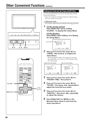
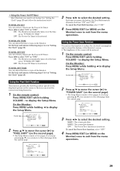
...: The screen gets dim. OFF: The Power-Off Timer is deactivated. On the Monitor: Press MENU while holding VOLUME - to display the Setup Menu. SET-UP MENU 2/2 PIXEL SHIFT : OFF POWER SAVE : OFF COLOR-REVERSE REFRESH reset all reset HOUR METER x100h : 123 MODEL NAME : GM-V42UG ADJUST: SELECT: EXIT: MENU 3 Press 2/3 to display the Setup Menu. Using the Pixel Shift Function This function periodically shift the position (pixels) of the screen will be reduced. 1 On the remote control: Press MENU/EXIT while...
...: The screen gets dim. OFF: The Power-Off Timer is deactivated. On the Monitor: Press MENU while holding VOLUME - to display the Setup Menu. SET-UP MENU 2/2 PIXEL SHIFT : OFF POWER SAVE : OFF COLOR-REVERSE REFRESH reset all reset HOUR METER x100h : 123 MODEL NAME : GM-V42UG ADJUST: SELECT: EXIT: MENU 3 Press 2/3 to display the Setup Menu. Using the Pixel Shift Function This function periodically shift the position (pixels) of the screen will be reduced. 1 On the remote control: Press MENU/EXIT while...
Instructions
Page 32
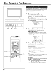
... the remote control: Press MENU/EXIT while holding 2 to "COLOR-REVERSE" (on the screen using the Color-Reverse On/Off Timer. Other Convenient Functions (Continued) 2 / 3 VOLUME - On the Monitor: Press MENU while holding VOLUME - SET-UP MENU 2/2 PIXEL SHIFT : OFF POWER SAVE : OFF COLOR-REVERSE REFRESH reset all reset HOUR METER x100h : 123 MODEL NAME : GM-V42UG ADJUST: SELECT: EXIT: MENU 3 Press 5/∞ to select the item you can move the cursor (3) to display the Setup Menu. START SET You...
... the remote control: Press MENU/EXIT while holding 2 to "COLOR-REVERSE" (on the screen using the Color-Reverse On/Off Timer. Other Convenient Functions (Continued) 2 / 3 VOLUME - On the Monitor: Press MENU while holding VOLUME - SET-UP MENU 2/2 PIXEL SHIFT : OFF POWER SAVE : OFF COLOR-REVERSE REFRESH reset all reset HOUR METER x100h : 123 MODEL NAME : GM-V42UG ADJUST: SELECT: EXIT: MENU 3 Press 5/∞ to select the item you can move the cursor (3) to display the Setup Menu. START SET You...

Instructions
Page 33
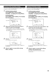
... the Monitor: Press MENU while holding VOLUME - Cursor (3) SET-UP MENU STATUS DISPLAY CONTROL LOCK REMOTE SWITCH HD SIGNAL MODE WHITE BALANCE TIMER 1/2 : OFF : OFF : MODE1 : 1080i ADJUST: SELECT: EXIT: MENU 2 Press 5/∞ to move to the other page from the current page. 3 Press 5/∞ to display the Setup Menu. OFF: The function is deactivated. Note: • Set the clock (see page 28) and select "TIMER," before using the Refresh On...
... the Monitor: Press MENU while holding VOLUME - Cursor (3) SET-UP MENU STATUS DISPLAY CONTROL LOCK REMOTE SWITCH HD SIGNAL MODE WHITE BALANCE TIMER 1/2 : OFF : OFF : MODE1 : 1080i ADJUST: SELECT: EXIT: MENU 2 Press 5/∞ to move to the other page from the current page. 3 Press 5/∞ to display the Setup Menu. OFF: The function is deactivated. Note: • Set the clock (see page 28) and select "TIMER," before using the Refresh On...
Instructions
Page 35
SET-UP MENU 2/2 PIXEL SHIFT : OFF POWER SAVE : OFF COLOR-REVERSE REFRESH reset all reset Are you can move the cursor (3) to display the Setup Menu. To cancel the reset, press MENU/EXIT (or MENU on the Monitor). 4 Press 3 again to display the Setup Menu. On the Monitor: Press MENU while holding VOLUME - The confirmation screen appears. The confirmation screen appears. to "all the Setup Menu settings. Cursor (3) SET-UP MENU STATUS DISPLAY CONTROL LOCK REMOTE SWITCH HD SIGNAL MODE WHITE BALANCE TIMER 1/2 : OFF : OFF : MODE1 : 1080i ADJUST: SELECT...
SET-UP MENU 2/2 PIXEL SHIFT : OFF POWER SAVE : OFF COLOR-REVERSE REFRESH reset all reset Are you can move the cursor (3) to display the Setup Menu. To cancel the reset, press MENU/EXIT (or MENU on the Monitor). 4 Press 3 again to display the Setup Menu. On the Monitor: Press MENU while holding VOLUME - The confirmation screen appears. The confirmation screen appears. to "all the Setup Menu settings. Cursor (3) SET-UP MENU STATUS DISPLAY CONTROL LOCK REMOTE SWITCH HD SIGNAL MODE WHITE BALANCE TIMER 1/2 : OFF : OFF : MODE1 : 1080i ADJUST: SELECT...

Instructions
Page 38
...Reset Confirmation Screen" SET-UP MENU 2/2 PIXEL SHIFT : OFF POWER SAVE : OFF COLOR-REVERSE REFRESH reset all reset Are you sure? "YES" then "NO" then MENU key. Menu Classifications (Continued) Setup Menu SET-UP MENU STATUS DISPLAY CONTROL LOCK REMOTE SWITCH HD SIGNAL MODE WHITE BALANCE TIMER 1/2 : OFF : OFF : MODE1 : 1080i ADJUST: SELECT: EXIT: MENU White Balance Adjustment Menu WHITE BALANCE:HIGH R GAIN G GAIN B GAIN sub menu reset : 000 :+ 001 :- 002 ADJUST: SELECT: EXIT: MENU Timer Menu TIMER PRESENT TIME POWER-ON SET POWER-ON TIME POWER-OFF SET POWER-OFF TIME reset...
...Reset Confirmation Screen" SET-UP MENU 2/2 PIXEL SHIFT : OFF POWER SAVE : OFF COLOR-REVERSE REFRESH reset all reset Are you sure? "YES" then "NO" then MENU key. Menu Classifications (Continued) Setup Menu SET-UP MENU STATUS DISPLAY CONTROL LOCK REMOTE SWITCH HD SIGNAL MODE WHITE BALANCE TIMER 1/2 : OFF : OFF : MODE1 : 1080i ADJUST: SELECT: EXIT: MENU White Balance Adjustment Menu WHITE BALANCE:HIGH R GAIN G GAIN B GAIN sub menu reset : 000 :+ 001 :- 002 ADJUST: SELECT: EXIT: MENU Timer Menu TIMER PRESENT TIME POWER-ON SET POWER-ON TIME POWER-OFF SET POWER-OFF TIME reset...

Instructions
Page 40
...;Set "COLOR-REVERSE"/"REFRESH" to "OFF" on or off. •Is the Power On/Off Timer activated? The remote control does not work . •Is the RGB B connecting cord long? •Set the SYNC TERM. Video image does not •Is the correct input selected? "AUTO." •Are signals (scanning frequency, etc.) to •Check if the signal is cut or shifted toward the Monitor, then operate the remote control. •Is the Control Lock...
...;Set "COLOR-REVERSE"/"REFRESH" to "OFF" on or off. •Is the Power On/Off Timer activated? The remote control does not work . •Is the RGB B connecting cord long? •Set the SYNC TERM. Video image does not •Is the correct input selected? "AUTO." •Are signals (scanning frequency, etc.) to •Check if the signal is cut or shifted toward the Monitor, then operate the remote control. •Is the Control Lock...

Instructions
Page 41
... the Monitor To Model Name: Plasma Display Monitor GM-V42UG/GM-V42UB The self-diagnostic lamps light or flash as usual. OVER" lights (or flashes) If "TEMP. OVER" lights in red. OVER & Flashes Your Name: Telephone No.: Address: 39 Self-diagnostic Indication When something abnormal occurs with the Monitor, this function informs you of the condition of the Monitor with self-diagnostic lamps, allowing for smooth service work. 1 2 3 Power lamp...
... the Monitor To Model Name: Plasma Display Monitor GM-V42UG/GM-V42UB The self-diagnostic lamps light or flash as usual. OVER" lights (or flashes) If "TEMP. OVER" lights in red. OVER & Flashes Your Name: Telephone No.: Address: 39 Self-diagnostic Indication When something abnormal occurs with the Monitor, this function informs you of the condition of the Monitor with self-diagnostic lamps, allowing for smooth service work. 1 2 3 Power lamp...

Instructions
Page 44
GM-V42UG/GM-V42UB PLASMA DISPLAY MONITOR Specifications (Continued) Pin assignment (Specifications for terminals) • Y/C terminal • RS-232C terminal This is a female type connector. 4 3 Pin number Signal name 1 GND (Y) 2 1 2 GND (C) 3 Y 4 C 5 4321 9 87 6 Pin number 1 2 3 4 5 Signal name DCD RD TD DTR GND Pin number 6 7 8 9 Signal name DSR RTS CTS RI • MAKE terminal • RGB Input Terminal 6 6 5 Pin number Signal name 7 4 3 1 2 1 2 3 4 GND 1 2 GND 3 SW2 8 4 SW1 5 5 SW DET 9 6 GND 10 Pin number Signal name...
GM-V42UG/GM-V42UB PLASMA DISPLAY MONITOR Specifications (Continued) Pin assignment (Specifications for terminals) • Y/C terminal • RS-232C terminal This is a female type connector. 4 3 Pin number Signal name 1 GND (Y) 2 1 2 GND (C) 3 Y 4 C 5 4321 9 87 6 Pin number 1 2 3 4 5 Signal name DCD RD TD DTR GND Pin number 6 7 8 9 Signal name DSR RTS CTS RI • MAKE terminal • RGB Input Terminal 6 6 5 Pin number Signal name 7 4 3 1 2 1 2 3 4 GND 1 2 GND 3 SW2 8 4 SW1 5 5 SW DET 9 6 GND 10 Pin number Signal name...


